COURSEWORK
maitri's IOT-001 course work. Lv 1
| maitri kulkarni | AUTHOR | ACTIVE |
Level 0
16 / 3 / 2026
TASK 1: 3D Printing:
Objective:
To understand the working of 3d printing,the types of 3d printers and their parts, types of filaments.To learn the procedure of slicing an stl file and printing it.
learnings:
-
Parts of 3d printers:

-
Gantry: a gantry is a mechanical frame or suppport strucutre that moves the build plate or print head in the x,y and z axes.
-
Build Plate: The print bed is the flat surface where the object is printed. It may be heated to help the plastic stick to the surface and prevent warping. The object builds layer by layer on this platform.
-
Filament: The filament is the plastic material used for printing. Common materials include:
-
PLA (Polylactic Acid) – easy to print
-
ABS (Acrylonitrile Butadiene Styrene) – stronger and heat resistant
-
PETG – strong and flexible
-
Most commonly used filament is pla
-
Extruder: he extruder feeds the printing material (filament) into the hot end. It consists of a motor,gear mechanism,filament feeder. It pushes the filament at a controlled speed during printing.
-
Nozzle: nozzle is the small metal tip at the end of the hot end through which molten filament is extruded onto the build plate
-
Types of 3d printers:
a. FDM(Fused deposition modelling): uses plastic as a filament like pla pr petg. Filament is melted and is deposited layer by layer.
b. SLA(stereolithography): uses resin liquid and uv laser hardens resin layer by layer.
c. DLP(digital light processing):same as SLA but uses projected light instead of uv laser to harden the resin.
d.Binder jetting: a liquid binding agent is selectively deposited to join layers of powdered material and form a solid object.
-
How to 3-D print a model?: The 3d model is designed using different CAD software such as Tinkercad,Fusion 360 etc. the 3d model is generated in the form of an stl file. This stl file is sliced. The 3d model is divided into hundreds or thousands of thin horizontal layers using slicer software like Ultimaker Cura,PrusaSlicer. These softwares generate a gcode after slicing. The gcode contains the details like the bed temperature, print speed,layer height, nozzle temperature etc.
- Infill Density: Determines how solid the print will be inside. Standard values: 10–20% for most models, but higher for stronger parts.
types of infill patterns: grid pattern, honeycomb , gyroid, lines, cubic etc.
reference: 3d printing
Task 2: API
Application Programming Interface (API)
Introduction
An Application Programming Interface (API) is a way for different software programs to communicate with each other. It defines a set of rules that allow one application to request data or services from another application. APIs are widely used in modern software systems because they make it easier for programs to share information and work together.
How an API Works
APIs usually follow a request–response model. A program sends a request to the API asking for certain data or an action. The API processes the request and sends back a response.
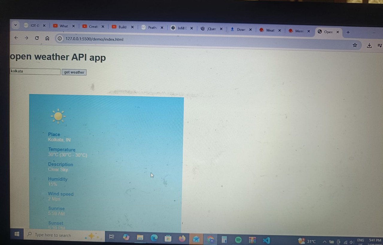
For example, when a weather application shows the temperature of a city, it often gets that information from a weather service API instead of measuring it itself.
Types of APIs
1. Open APIs
Open APIs, also called public APIs, are available for developers and can be accessed with minimal restrictions.
2. Internal APIs
Internal APIs are used within an organization to allow communication between different internal systems.
3. Partner APIs
Partner APIs are shared with specific business partners and usually require authentication to access.
4. Composite APIs
Composite APIs combine multiple API requests into a single call, helping applications get data from several sources efficiently.
Advantages of APIs
- They allow different applications to communicate easily.
- Developers can reuse existing services instead of building everything from scratch.
- APIs help speed up development.
- They allow applications to connect with external services like payment gateways or maps.
reference: api
Task 3: Working with Github
task 3
Task 7:Create a Portfolio Webpage
task 7
Task 8: Writing Resource Article using Markdown
learnt how to write a report using markdown language on vs code. learnt how to write headings, different text formats like bold,italics , cutoff etc. learnt how to add an image and url in markdown. report:
Task 9:Tinkercad
objective:
To simulate a simple circuit using an ultrasonic sensor to estimate the distance between an obstacle and the sensor. Display the results on the serial monitor.
- Learnt how to simulate working of simple circuits
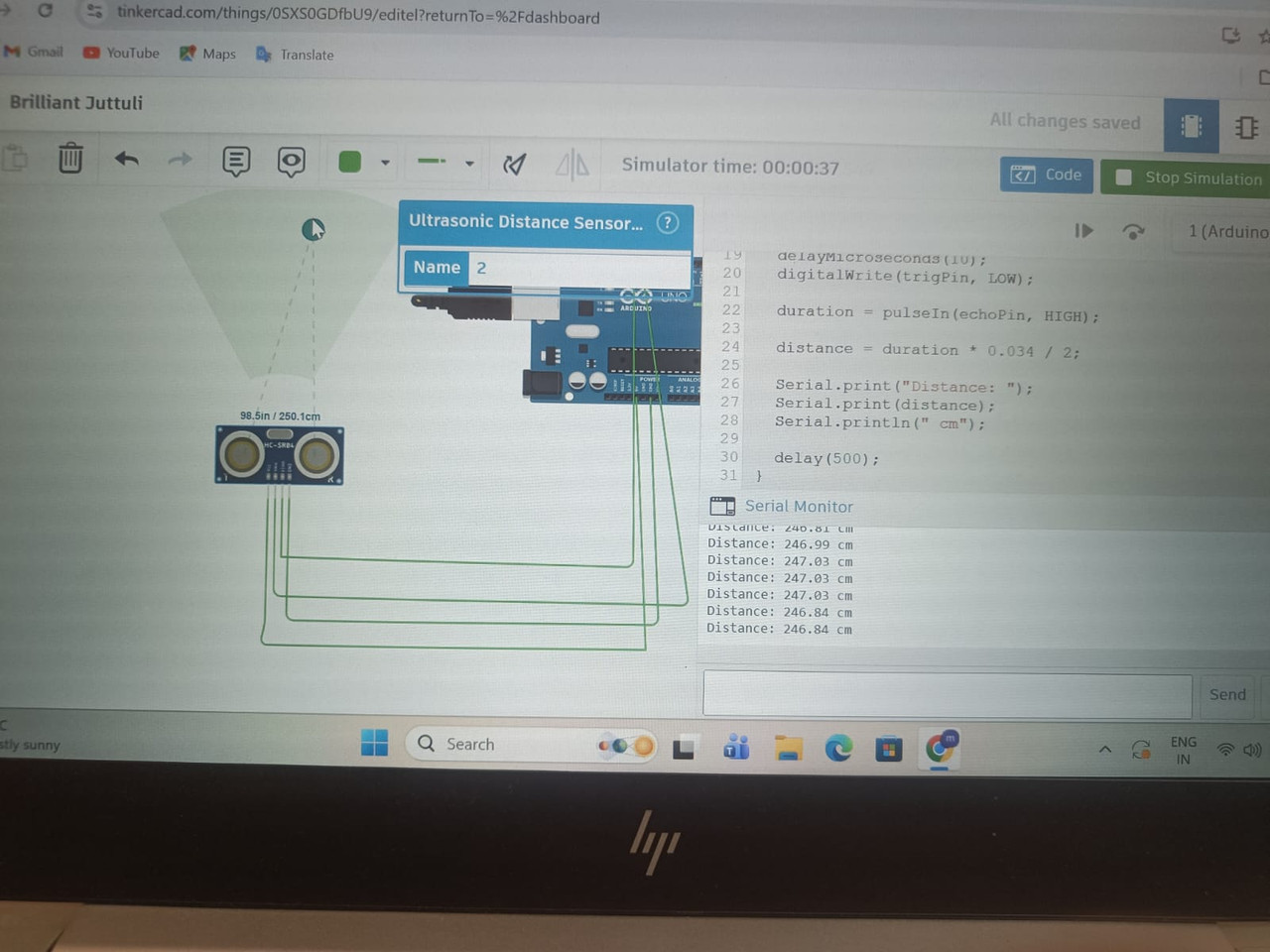
- Learnt the working of ultrasonic sensors
Ultrasonic sensors:
An ultrasonic sensor is a device used to measure the distance of an object by using high-frequency sound waves (ultrasound). These waves have frequencies above 20 kHz, which humans cannot hear.
Components of an Ultrasonic Sensor:
- Transmitter (Ultrasonic Transducer):
-
Converts electrical energy into ultrasonic sound waves.
-
Sends the sound waves toward the object.
- Receiver:
-
Receives the echoed sound waves reflected back from the object.
-
Converts the sound waves back into electrical signals.
- Control Circuit:
-
Generates the trigger signal to start the transmission.
-
Processes the received echo signal.
-
Calculates the time taken for the sound wave to return.
- Microcontroller / Processing Unit
- Used in many systems to calculate the distance based on the time of flight.
Examples: microcontrollers like Arduino or ESP32.
- Power Supply
- Provides electrical power for the sensor and circuit.
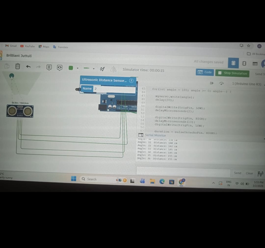
Creating a radar system using uktrasonic sensor and servo motors:
Task 10:Speed Control of DC Motor
Objective
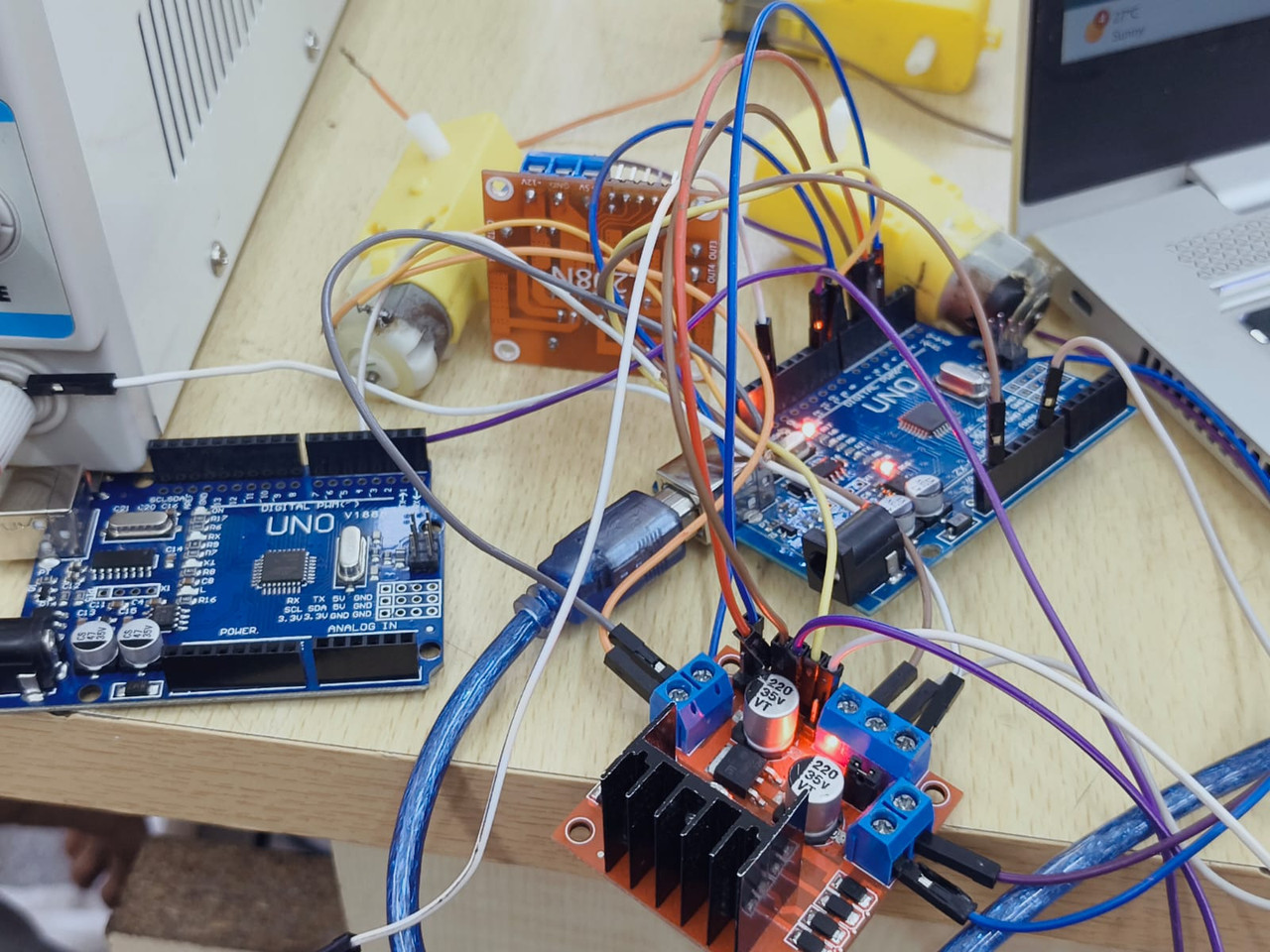
To explore basic techniques for controlling DC motors and understand how to control a DC motor using the L298N motor driver and Arduino UNO. The task involves controlling the speed of a 5V BO motor using PWM and simulating the circuit before performing it practically.
Components Required
- Arduino UNO
- L298N Motor Driver Module
- DC Motor
- External Power Supply / Battery
- Jumper Wires
- Breadboard
Introduction
A DC motor converts electrical energy into mechanical energy. In many robotics and embedded systems applications, controlling the speed and direction of a motor is essential.
However, a microcontroller cannot drive a motor directly because:
- Motors require higher current.
- Motors generate back EMF which can damage the microcontroller.
Therefore, a motor driver is used between the motor and the microcontroller.
L298N Motor Driver
The L298N is a dual H-bridge motor driver that allows control of:
- Speed of the motor
- Direction of rotation
Important Pins
| Pin | Function |
|---|---|
| IN1 | Direction control |
| IN2 | Direction control |
| ENA | Speed control (PWM) |
| OUT1 | Motor terminal |
| OUT2 | Motor terminal |
| VCC | Motor power supply |
| GND | Ground |
H-Bridge Concept
An H-Bridge is an electronic circuit that allows a motor to rotate in both directions.
| IN1 | IN2 | Motor Direction |
|---|---|---|
| HIGH | LOW | Forward |
| LOW | HIGH | Reverse |
| LOW | LOW | Stop |
Circuit Connections
| L298N Pin | Arduino UNO |
|---|---|
| ENA | Pin 9 (PWM) |
| IN1 | Pin 8 |
| IN2 | Pin 7 |
| GND | GND |
| VCC | 5V / External supply |
Motor terminals are connected to OUT1 and OUT2.
Working Principle
- Arduino sends signals to the L298N driver.
- IN1 and IN2 control the direction of rotation.
- ENA receives a PWM signal from Arduino.
- The PWM signal controls the motor speed.
PWM varies between 0–255:
- 0 → Motor OFF
- 255 → Maximum speed
Task 11:LED Toggle Using ESP32
Objective
To learn the working of the ESP32 microcontroller and create a standalone web server that can control an LED connected to the ESP32 GPIO pins using the Arduino IDE.
Components Required
- ESP32 Development Board
- 2 LEDs
- 330Ω Resistors
- Breadboard
- Jumper Wires
- Computer with Arduino IDE
Introduction
The ESP32 is a powerful microcontroller with built-in Wi-Fi and Bluetooth capabilities. It is widely used in Internet of Things (IoT) applications because it can connect directly to a wireless network and communicate with web servers.
In this experiment, the ESP32 is programmed to act as a web server. When a user opens the ESP32's IP address in a web browser, a webpage appears with buttons that allow the user to turn an LED ON or OFF.
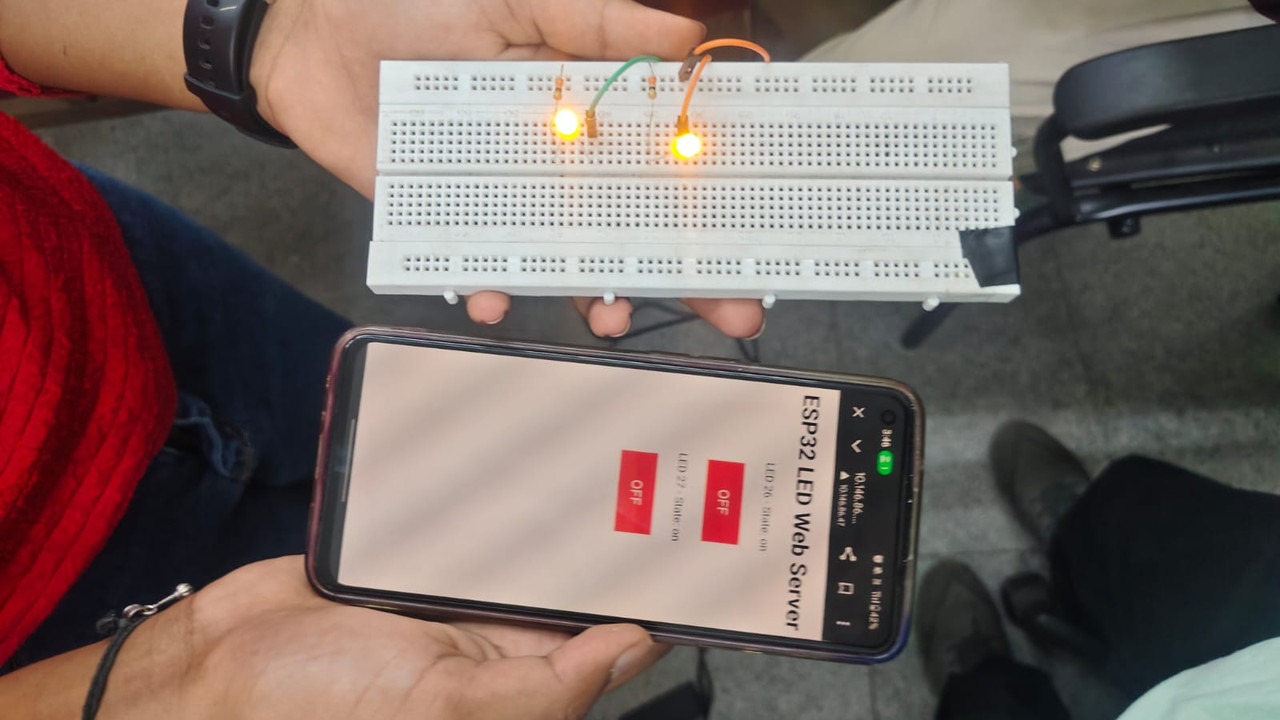
Working Principle
- The ESP32 connects to a Wi-Fi network.
- It starts a web server.
- When a user enters the ESP32 IP address in a browser, a control webpage appears.
- The webpage contains ON and OFF buttons.
- Pressing the buttons sends commands to the ESP32 to control the LED.
Task 12: Soldering Prerequisites
task 12
Task 13: 555 astable multivibrator with duty cycle 60%
Task 16: Datasheets report writing:
Objective
Learnt about the ICs used in L293D, PWM and the H-bridge.
Report:
datasheet report writing on l293d motor driver
Task 17:Introduction to VR
Task 14 : Karnaugh Maps and Deriving the logic circuit
Burglar Alarm Using Logic Gates (K-Map Design)
Aim
To design and simulate a burglar alarm circuit using Karnaugh Map (K-map) and basic logic gates in Logic.ly.
Theory
A burglar alarm system detects suspicious conditions related to a door and key.
The alarm turns ON when the door and key states do not match.
Examples:
- Door open without key → Alarm ON
- Door closed but key pressed → Alarm ON
- Door closed normally → Alarm OFF
- Door opened with key → Alarm OFF
To simplify the logic expression, a Karnaugh Map (K-map) is used.
Truth Table
| Door (D) | Key (K) | Alarm (A) |
|---|---|---|
| 0 | 0 | 0 |
| 0 | 1 | 1 |
| 1 | 0 | 1 |
| 1 | 1 | 0 |
| Where: |
- 0 = Closed / Not pressed
- 1 = Open / Pressed
Karnaugh Map
| D \ K | 0 | 1 |
|---|---|---|
| 0 | 0 | 1 |
| 1 | 1 | 0 |
From the K-map we obtain the Boolean expression:
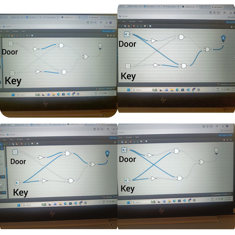
A = D'K + DK'
This is equivalent to the XOR operation.
Working
The circuit checks the states of the door and key.
- If the door opens without the key being pressed, the alarm activates.
- If the key is pressed while the door is closed, the alarm activates.
- If the door and key states match, the alarm remains OFF.
This behavior is the same as an XOR logic function.