BLOG · 21/3/2026
LEVEL 0 : Task 13
555 astable multivibrator with 60% duty cycle

Task 13: 555 astable multivibrator with duty cycle 60%
Objective
To design a 555 timer astable multivibrator with a duty cycle of approximately 60%, implement the circuit on a breadboard, and observe the output waveform using a Digital Storage Oscilloscope (DSO).
Introduction
A 555 timer is a widely used integrated circuit in electronics that can operate in three modes:
- Astable mode
- Monostable mode
- Bistable mode
In astable mode, the circuit continuously switches between HIGH and LOW states without any external triggering, producing a square wave output.
This circuit is commonly used in:
- LED flashing circuits
- Pulse generation
- Clock signals
- PWM control circuits
Components Required
- 555 Timer IC
- Resistors (R1 and R2)
- Capacitor (C)
- Breadboard
- Jumper wires
- Power supply (5V or 9V)
- Digital Storage Oscilloscope (DSO)
Astable Multivibrator Circuit
In astable mode, the capacitor continuously charges and discharges through resistors R1 and R2, producing a periodic output waveform.
Important Pins of 555 Timer
| Pin | Name | Function |
|---|---|---|
| 1 | GND | Ground |
| 2 | Trigger | Starts timing cycle |
| 3 | Output | Output signal |
| 4 | Reset | Resets the timer |
| 5 | Control Voltage | Controls threshold voltage |
| 6 | Threshold | Ends timing cycle |
| 7 | Discharge | Discharges capacitor |
| 8 | VCC | Power supply |
Circuit Operation
- The capacitor charges through R1 and R2.
- When the capacitor voltage reaches 2/3 of VCC, the output switches LOW.
- The capacitor then discharges through R2.
- When the voltage falls to 1/3 of VCC, the output switches HIGH again.
- This cycle repeats continuously, generating a square wave output.
- resistors used are 5 ohms and 10 ohms
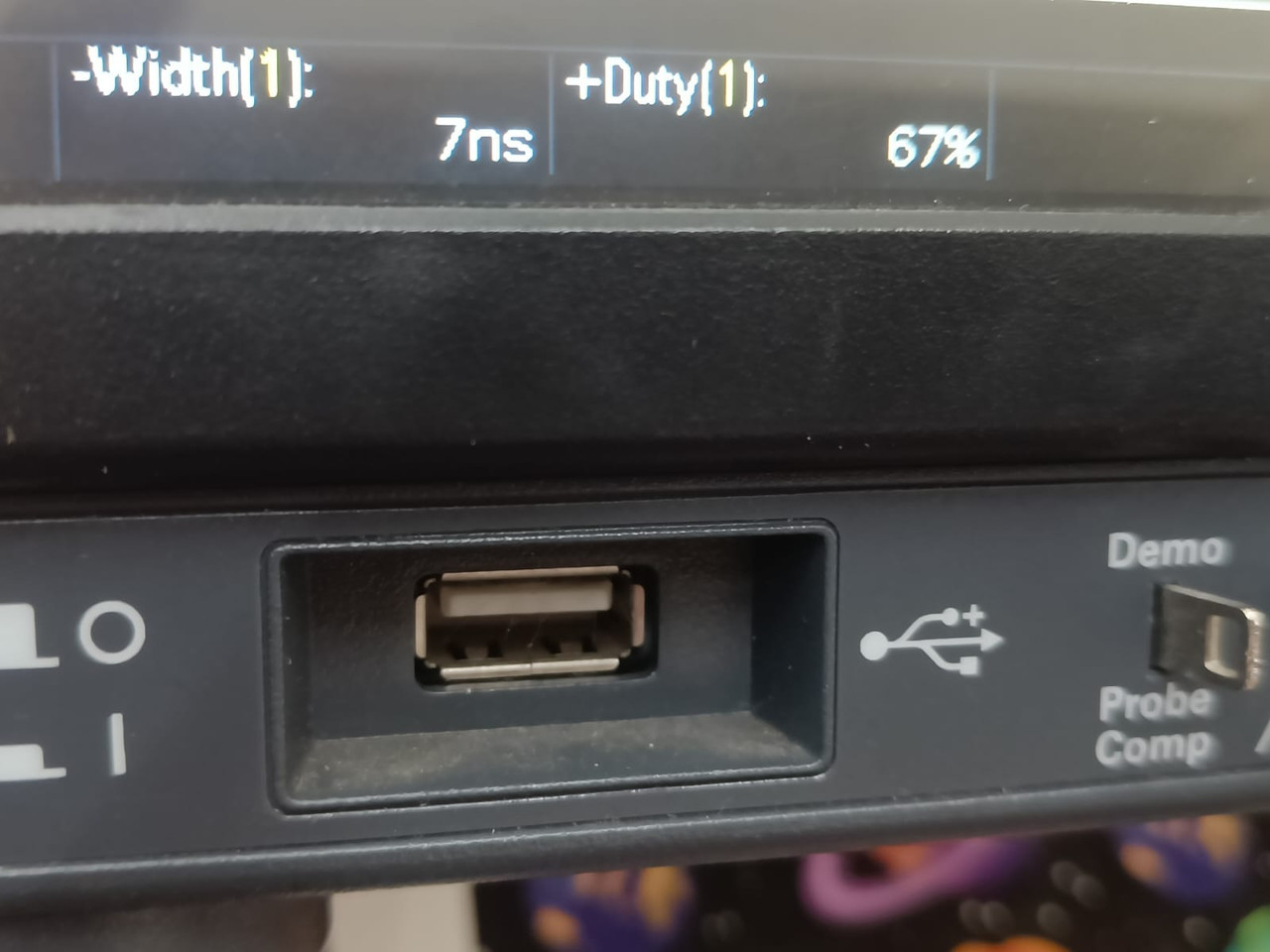
Observation
The output waveform observed on the DSO is a rectangular (square) waveform.
The signal alternates between HIGH and LOW states with a duty cycle close to 60%.