2 / 10 / 2024
TASK 1
LT SPICE AND KICAD
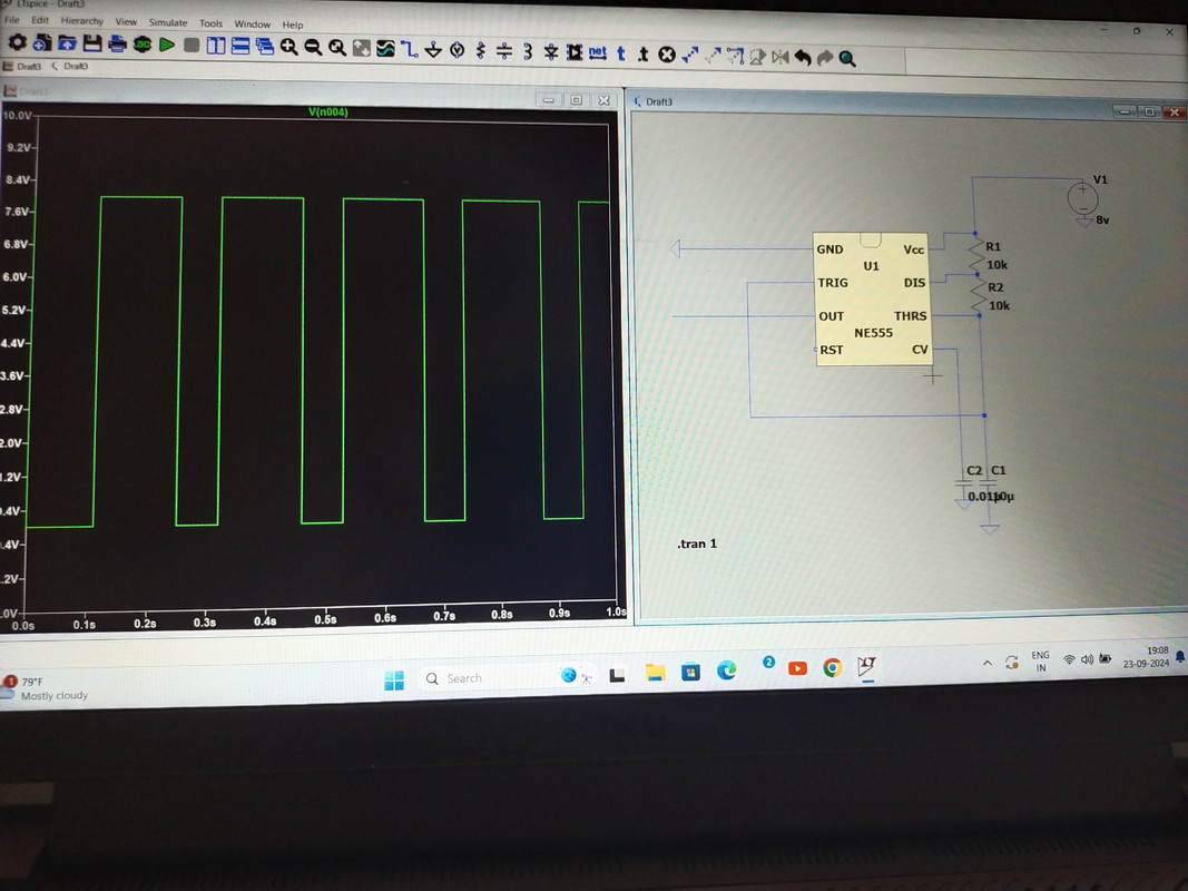
To design and simulate an astable multivibrator using 555 timer in LT SPICE
STEPS TO USE LT SPICE
1 Download and install LT SPICE from official website
2 Open LT SPICE and create new schematics using filebrator such as resistors, capacitor , 555IC, Power supply and ground
4 Connect the circuit components using wire for all the 8 pins as shown in figure
5 set the components value for R1=R2=10K and C=0.01uf
6 Now for Simulation click on run main icon to set up and choose transient analysis and stop time 1sec run simulation and observe output waveform
7 after simulation runs click on output node pin3 to observe the square wave
TASK 2
SPEED CONTROL OF DC MOTOR
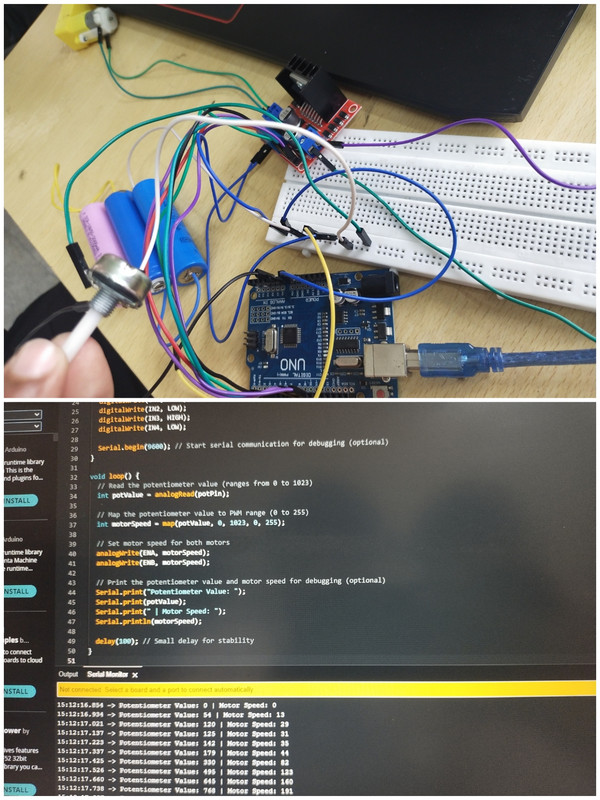
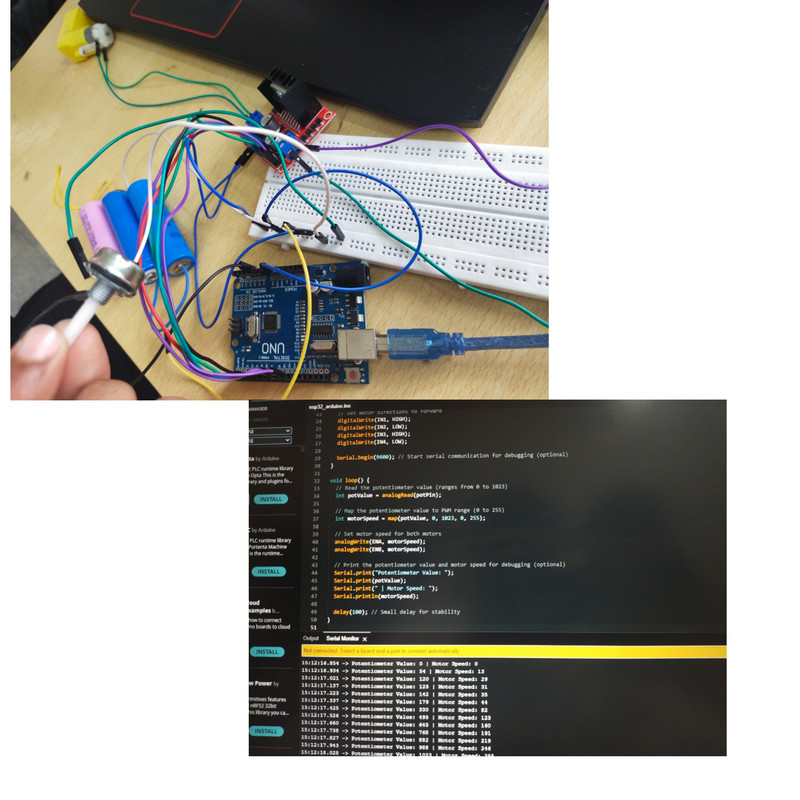
In this task learnt about L293D Dual H-bridge motor driver IC which is used to contorl the speed of two DC motor it has 2 enable pins connected to motors and 4 inputs pins to control the direction and output pin connected to motor terminals.
To control the speed of motor we use PWM Pulse width modlution pins that is the digital pins from 1 to 9 in the arduino and by varying the duty cycle of PWM signal we can control voltage delivered to motor which further controls the speed,.by making the arduino connections with VRPS and DC motors to control speed with help of Potentiometer we can do the task successfully
TASK 3
DIRECTION CONTROL OF DC MOTOR
To control the drirection we require the allmsot
the same components used in previous task such as Arduino board L293D motor DC
motor Power supply Breadboard Jumper wires etc,
Here the control pins IN1 and IN2 are used to control the direction of DC motor in
forward and reverse direcion as per our need If IN1 is High and IN2 is low it moves in
forward direction and if we reverse the pin it moves in opposite direction. by changing
the arduino code and running we can the output in serial monitor and achieve the Task.
 Task 4
TEMPERATURE DETECTION
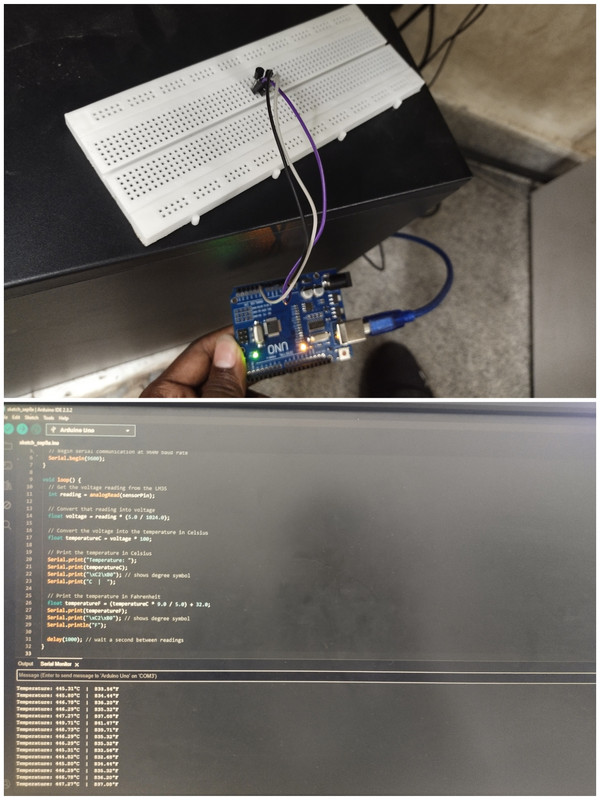
In this task we will measure temperature using an LM35 sensor and arduino and display it on serial monitor
COMPONENTS REQUIRED
LM35 Sensor ,Arduino biard , jumper wires, Breadboard
CONNECTIONS OF LM35 SENSOR
VCC (PIN1)- 5V on Arduino
GROUND(PIN3)- GND ON Arduino
Output(PIN2)- ANALOG PIN(A0) ON Arduino
The LM35 sensor reads the Temperature, coverts analog signal to celcius, and outputs it to serial monitor for the delay given in the code and we should be careful while using soldering gun should not make the physical contact with the sensor just measure the air temperature around it
TASK 5
TEMPERATURE AND HUMIDITY DETECTION
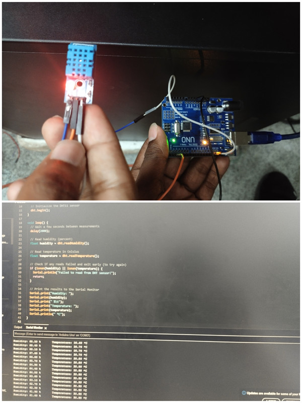
To measure temperature and humidity using the DHT11 sensor and display the readings on an LCD, you can follow this general setup:
Components:
Arduino (e.g., Uno) DHT11 Temperature and Humidity Sensor Jumper wires Breadboard
Wiring:
- DHT11 Sensor: VCC → 5V on Arduino GND → GND on Arduino Data Pin → Digital pin (e.g., D2)
The DHT11 is a digital sensor, It uses a single data pin to send temperature and humidity readings to the microcontroller in a digital format. This means the values are already processed inside the sensor, and you don't need to perform any analog-to-digital conversion, as you would with analog sensors. The data is transmitted in a serial digital signal, which can be read using a digital pin on the Arduino. and further output is displayed on the serial monitor .
TASK 6
BLDC MOTOR AND HALL EFFECT SENSOR
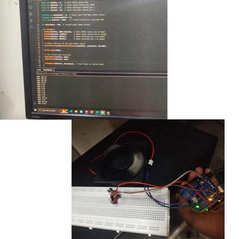
To measure the speed of a BLDC motor using Hall effect sensor and display it on a serial monitor , here we use hall effect sensor to detect the motor's rotations.
COMPONENTS NEEDED;
ROTATING MOTOR, HALL EFFECT SENSOR,ARDUINO UNO, BREADBOARD,JUMPER WIRES,
CONNECTIONS
VCC-5V ON ARDUINO GND-GND ON ARDUINO DATA - DIGITAL PIN D2
EXPLAINATION
The hall effect sensor is connected to digital pin of arduino and each pulse is detected when the sensor detects the magnet passed and pulse count is done in terms of RPM the calculated RPM is displayed every second on the Serial monitor.
TASK 7
AUTOMATIC DOOR OPENER SYSTEM
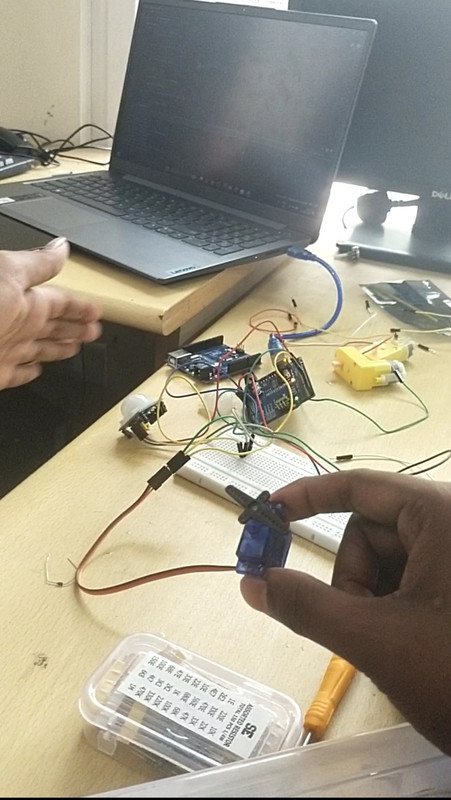
To replace the CD tray mechanism with a servo motor using a PIR sensor and Arduino, here’s a general approach:
Components Required:
Arduino
PIR sensor
Servo motor
Jumper wires
Breadboard (optional)
Power supply (if needed)
PIR connections
- Connect the PIR sensor to the Arduino:
VCC: Connect to Arduino 5V.
GND: Connect to Arduino GND.
OUT: Connect to a digital pin (e.g., D2).
Servo motor connections
- Connect the Servo motor to the Arduino:
Signal (Control pin): Connect to a PWM pin (e.g., D9).
Power (VCC): Connect to 5V or external power supply.
Ground: Connect to GND.
Working
- Programming the Servo motor to smoothly open/close the door based on the PIR sensor detection:
When motion is detected, the servo rotates to open the door.
After a 5 seconds delay, it smoothly returns to the closed position.
TASK 8
UNDERSTANDING 555 TIMER AND LDR
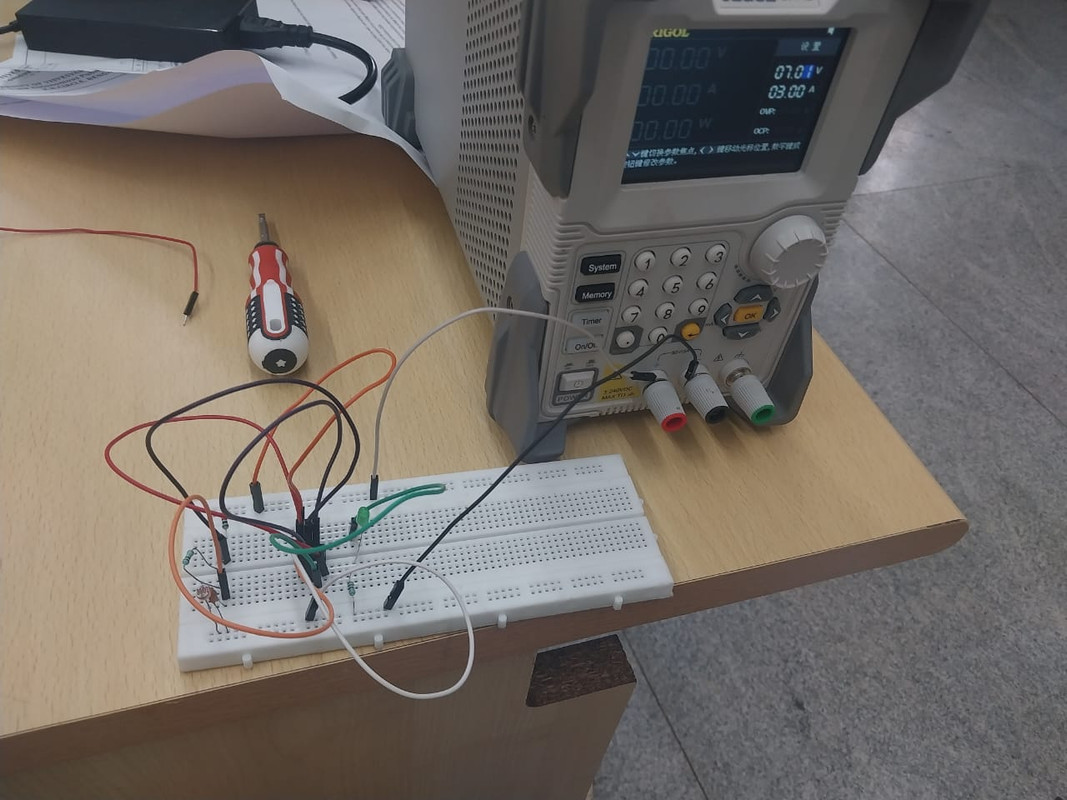
The project aims to design an automated headlight control system that activates a headlight when the surrounding environment becomes dark and turns it off in bright light conditions using a 555 Timer IC and an LDR (Light Dependent Resistor).
COMPONENTS REQUIRED; 555IC, LDR, RESISTORS-1K,10K,POT,CAPACITORS,POWER SUPPLY,BREADBOARD.
CIRCUIT OPERATION; The LDR resistance decreases with increase in the light intensity.
Bright light: The LDR has low resistance, causing the NE555 to output a low signal, keeping the headlight off.
Darkness: The LDR’s resistance increases, raising the voltage at Pin 2 trigger pin of the NE555, causing the output to go high, activating the relay, and turning on the headlight. The system is useful for vehicles or outdoor light setups where automated control is preffered.
TASK 9
SOLAR TRACKER
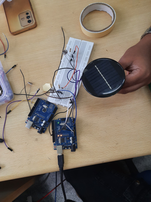
The goal of this project is to design and implement a solar tracking system using servos and light-dependent resistors (LDRs) to follow the sun's position and maximize the energy absorbed by a solar panel using ARDUINO.
COMPONENTS REQUIRED ; SERVO MOTORS, ARDUINO,LDR'S,RESISTORS ,POWER SUPPLY,SOLAR PANEL(mounted on servo motor to absorb energy).
CONNECTIONS; Connect each LDR in a voltage divider circuit with a 10kΩ resistor.
One side of each LDR goes to 5V, and the other connects to one end of a 10kΩ resistor.
The junction of the LDR and resistor goes to an analog pin on the Arduino.
The other end of the 10kΩ resistors connects to ground.
- Connect the servo motor to a digital pin (e.g., pin 9), with power and ground connected to 5V and GND, respectively.
WORKING; The code reads the light intensity values from both LDRs. If one LDR detects significantly more light than the other, the Arduino adjusts the servo motor to rotate the solar panel toward the light source. This setup tracks the sun horizontally. For a more complex system, you could add another set of LDRs and servos to track both horizontally and vertically.
TASK 10
AUTO NIGHT LAMP USING LED FOR ELECTRIC VEHICLES
An Auto Night Lamp for Electric Vehicles (EVs) using LEDs can be designed to turn on automatically when it gets dark, enhancing safety by improving visibility. This project typically relies on a light-dependent resistor (LDR) to detect ambient light and control an LED.
COMPONENTS NEEDED; LDR, RESISTOR 10K AND 1K, TRANSISTOR , POWER SUPPLY, BREADBOARD AND JUMPER WIRES.
WORKING; the LDR detects the ambient light level , when the light level is very low the LDR resistance increases ,, The LED lights up automatically when the light level falls below threshold .
APPLICATIONS
1 Automatic headlight for EV'S
2 Energy efficient lightning
3 Enhanced safety for pedestrian and other vehicles.
4 Street lamp assistance
5 Emergency vehicles

