31 / 3 / 2025
TASK 2 - SPI COMMUNICATION
SPI (Serial Peripheral Interface) communication allows one device (called the master) to communicate with one or more devices (called slaves) using a set of standard communication lines. In the case of using two Arduino boards, one will be the master, and the other will be the slave.
Overview of the SPI Pins: MISO (Master In Slave Out): This line sends data from the slave to the master.
MOSI (Master Out Slave In): This line sends data from the master to the slave.
SCK (Serial Clock): This is the clock signal generated by the master.
SS (Slave Select): This pin is used to select the slave device for communication.
HARWARE CONNECTIONS
MISO (Master) PIN12 → MISO PIN 12 (Slave)
MOSI PIN11 (Master) → MOSI PIN11(Slave)
SCK PIN13 (Master) → SCK PIN13 (Slave)
SS PIN10 (Master) → SS PIN10 (Slave) (This pin should be set to LOW on the slave for communication)
Connect Ground (GND) of both Arduino boards together.
STEPS TO RUN
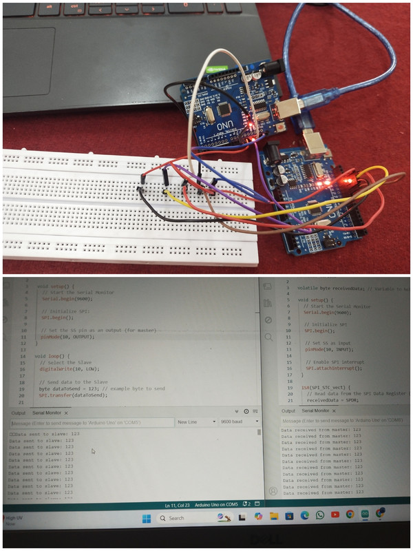
- Upload the slave code to one arduino and master code to the other.
2.Open the serial monitor fof the slave and master arduino to view the sent and recieved messages
3.The master has sent 123 to the slave and slave has recieved the message 123 which can be seen in the serial monitor.
TASK 3 I2C CONTROL
I2C communication:- I2C (Inter-Integrated Circuit) is a serial communication protocol that allows multiple devices to communicate with each other over two wires: SDA (data line) and SCL (clock line). You can use I2C to communicate between two Arduino Uno boards, where one acts as the master and the other as the slave.
Hardware connections: #SDA pin A4 of master Arduino to SDA pin A4 of slave Arduino #SCL pin A5 of master Arduino to SCL pin A5 of slave Arduino
Connect ground pin of both Arduino with each other
Steps to Run
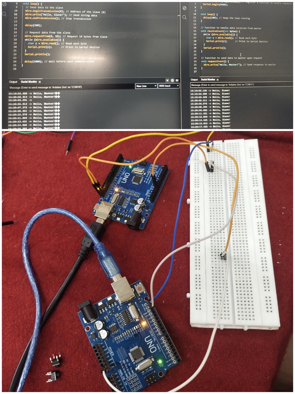
- Upload the slave code to one Arduino and the master code to the other.
- Open the Serial Monitor for the slave Arduino to view the received messages.
- The master will send "Hello Slave!" to the slave every second. Result : Thus I2C is very simple and effective way of communication between multiple Arduino devices.
TASK 5 - SPEED CONTROL OF BLDC
Speed control of a BLDC (Brushless DC) motor using Arduino involves using PWM (Pulse Width Modulation) to regulate the speed of the motor. Typically, this is done through an ESC (Electronic Speed Controller) that drives the BLDC motor, and the Arduino provides the PWM signal to control the speed.
Components Required: Arduino Board
BLDC Motor
Electronic Speed Controller (ESC)
Power supply for the BLDC motor and ESC
Potentiometer
Jumper wires
CIRCUIT CONNECTIONS : BLDC Motor and ESC Connections:
BLDC Motor Wires: The ESC will have three wires for connecting to the BLDC motor (usually labeled U, V, and W).
Power Supply for ESC: Connect the positive terminal of the power supply to the positive input terminal on the ESC and the negative terminal to the negative input terminal of the ESC.
ESC to Arduino PWM Pin: The ESC typically uses a 3-wire connection, where the signal wire (usually white or yellow) is connected to one of the PWM pins on the Arduino (e.g., Pin 9). The VCC and GND wires of the ESC should be connected to the 5V and GND pins of the Arduino respectively.
STEPS TO RUN
-
Make sure we have made the connections properly.
-
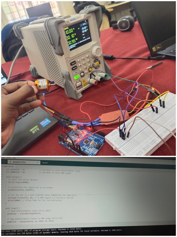
Upload the arduino code this code will use PWM to control the speed of the BLDC motor using an ESC
3.Make sure about the power supply the ESC and BLDC motor are powered by a suitable power supply. The Arduino is powered separately via USB or external 5V supply.
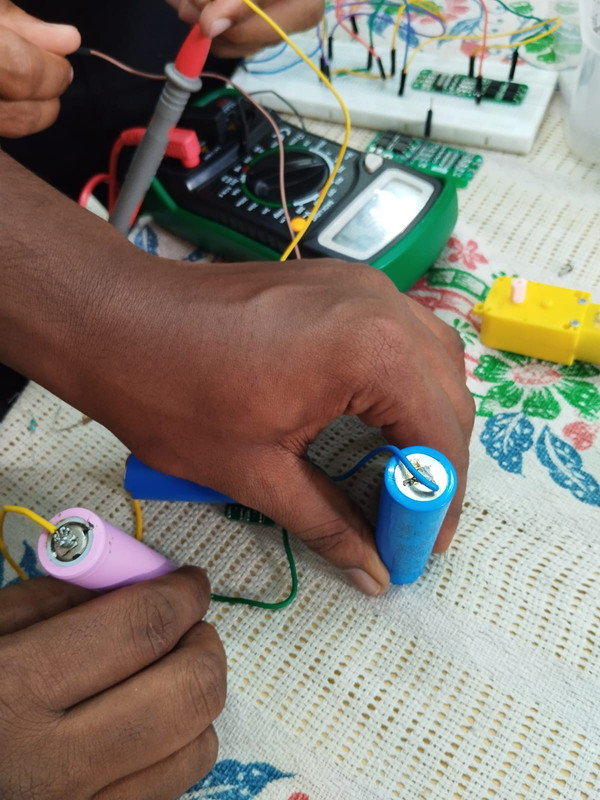
Task 7 - Make a Lithium-ion Battery Pack
Constructed a lithium-ion battery pack using three cells to supply a balanced voltage and current, ensuring efficient energy management and safety in power delivery. The pack is designed to meet the requirements of the application with a focus on reliability.
If you're connecting cells in series, you’ll connect the positive terminal of one cell to the negative terminal of the next cell, and so on.
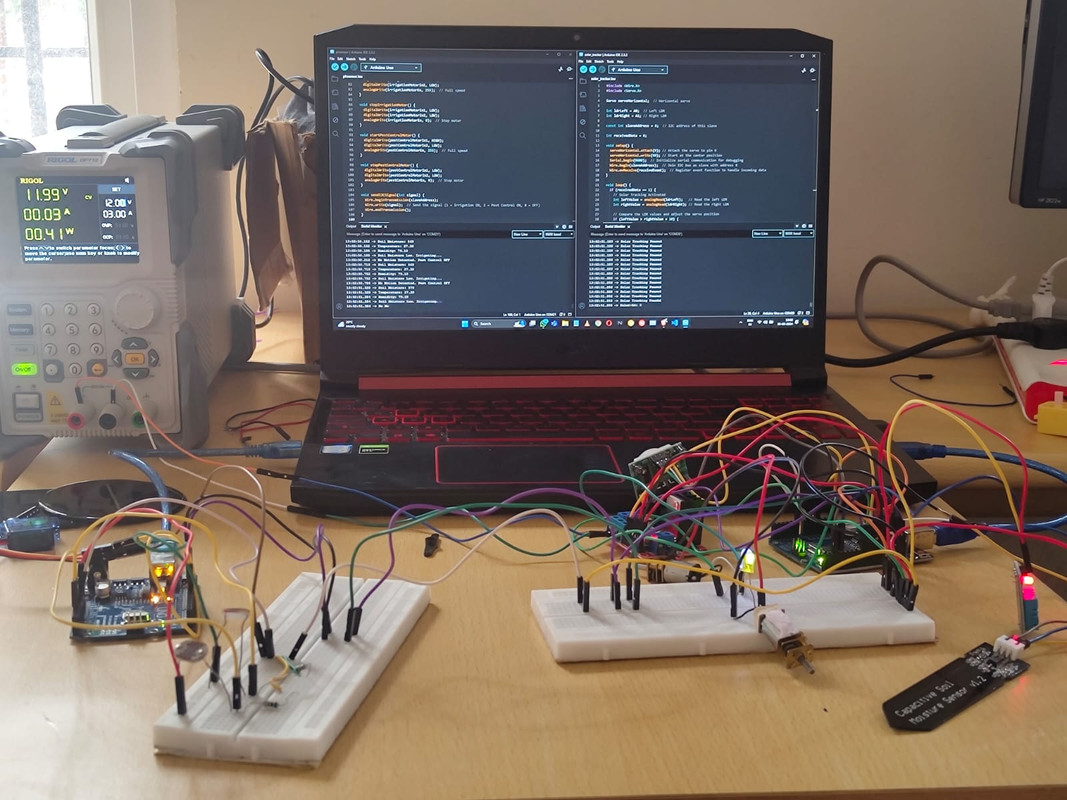
TASK 8 Working for Multiple sensors
Developed an automated irrigation system using arduino. Integrated multiple sensors to monitor soil moisture and environmental conditions, ensuring efficient water usage for optimal crop growth, and used the system to automate the irrigation process.