COURSEWORK
Sourav's EV-RE-001 course work. Lv 3
| Sourav Kumar | AUTHOR | ACTIVE |
21 / 7 / 2024
TASK 1
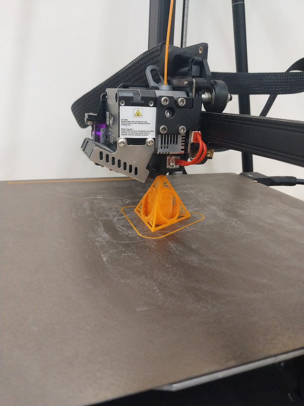
3D PRINTING
- Objective: The objective of this task was to learn and execute the process of 3D printing using Ultimaker Cura software, focusing on understanding STL files, slicing them, configuring printer settings, and successfully printing a model.
Methodology:
-
Understanding 3D Printing Basics:
- Researched and understood the fundamental components of a 3D printer including the extruder, build plate, and XYZ axes.
- Learned about the role of slicing software in converting STL files into instructions (G-code) that the printer can understand.
-
STL Files and Slicing:
- Researched the STL file format and its importance in 3D printing.
- Utilized Ultimaker Cura to import STL files and configure slicing settings:
- Explored settings such as layer height, infill density, print speed, and support structures to optimize print quality.
- Experimented with different parameters to understand their impact on print outcome.
-
Printer Settings and Configuration:
- Learned about PLA filament properties and its recommended settings (e.g., bed temperature around 60°C).
- Configured Ultimaker Cura for a specific printer model to ensure compatibility and accurate G-code generation.
- Adjusted settings such as infill density (set to 20-25%) and print speed to balance between print quality and speed.
-
Execution:
- Obtained an STL file from an online repository, ensuring it was suitable for the chosen printer and filament.
- Imported the STL file into Ultimaker Cura, sliced it, and generated G-code based on optimized settings.
- Transferred the G-code to the 3D printer and initiated the printing process.
- Monitored the initial layers to verify adhesion and quality, ensuring the print proceeded smoothly.
-
Outcome:
- Successfully printed the model, achieving satisfactory results in terms of dimensional accuracy and surface finish.
- Evaluated the print for any defects or improvements needed in future prints.
Conclusion: This task provided a comprehensive introduction to the 3D printing process, from understanding the underlying technology to hands-on experience with slicing software and printer configuration. By following structured steps and leveraging Ultimaker cura effectively, the objective of printing a model from an STL file was achieved. And model was prepared.
###TASK2 : ###Working with pandas and matplotlib:
Objective: The objective of this task was to demonstrate proficiency in data visualization using pandas and matplotlib by creating three types of plots: a line graph, a bar graph, and a scatter plot. These visualizations were based on a sample dataset representing car sales data over several years.
Methodology:
Data Preparation:
A fictitious dataset was created to simulate car sales data over a five-year period (2018-2022). The dataset included columns for 'Year', 'Sales', and 'Profit', providing the necessary variables for visualization.
Step 1: Import Required Libraries
import pandas as pd import matplotlib.pyplot as plt
Step 2: Create Sample Data
For demonstration purposes, we'll create a simple DataFrame with fictitious car sales data. data = { 'Year': [2018, 2019, 2020, 2021, 2022], 'Sales': [500, 600, 750, 800, 900], 'Profit': [50, 70, 80, 85, 100] }
df = pd.DataFrame(data)
Step 3: Line Graph
Let's plot a line graph showing the trend of car sales over the years. plt.figure(figsize=(8, 5)) plt.plot(df['Year'], df['Sales'], marker='o', linestyle='-', color='b', label='Sales') plt.title('Car Sales Over Years') plt.xlabel('Year') plt.ylabel('Sales') plt.grid(True) plt.legend() plt.tight_layout() plt.show()
Step 4: Bar Graph
Next, let's create a bar graph to visualize the profit made each year. plt.figure(figsize=(8, 5)) plt.bar(df['Year'], df['Profit'], color='g', alpha=0.7, label='Profit') plt.title('Profit from Car Sales') plt.xlabel('Year') plt.ylabel('Profit ($ millions)') plt.grid(axis='y') plt.legend() plt.tight_layout() plt.show()
Step 5: Scatter Plot
Finally, let's create a scatter plot to explore the relationship between sales and profit. plt.figure(figsize=(8, 5)) plt.scatter(df['Sales'], df['Profit'], color='r', marker='o', s=100, alpha=0.5) plt.title('Scatter Plot of Sales vs Profit') plt.xlabel('Sales') plt.ylabel('Profit') plt.grid(True) plt.tight_layout() plt.show()
###TASK 3:
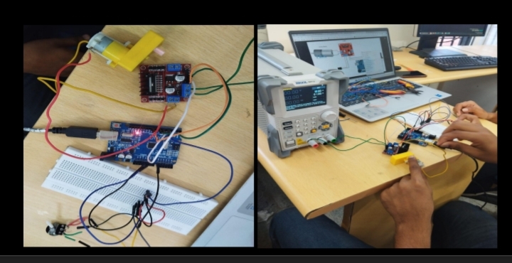
SPEED CONTROL OF DC MOTOR
Controlling DC motors using an Arduino and an L298N motor driver involves several steps, both in simulation (using Tinkercad) and in hardware. Here's a detailed guide on how to achieve this:
- Components Needed: Arduino UNO board L298N motor driver module DC motor (5V BO motor in this case) Power source (battery pack or another appropriate power supply) Jumper wires Breadboard (optional but recommended)
- Understanding the L298N Motor Driver: The L298N motor driver is an H-Bridge motor driver that allows bidirectional control of DC motors. It can control two motors independently or a single motor with increased current capacity. Key features include:
Input Voltage: Supports a wide range of input voltages (5V to 35V). Current Capacity: Can handle up to 2A per channel (with a heatsink). Control: Enables precise control over motor speed and direction using PWM (Pulse Width Modulation) signals from the Arduino. 3. Circuit Design on Tinkercad: Setup the Components:
Place an Arduino UNO board and a DC motor on the Tinkercad workspace. Add an L298N motor driver module and connect it to the Arduino and motor. Connect Components:
Arduino to L298N Connections: Connect Arduino digital pins to the IN1, IN2, ENA (enable) pins of the L298N for motor control. Connect Arduino PWM pins (e.g., 5 and 6) to the ENA and ENB pins of the L298N for speed control using PWM. Connect Arduino GND to the GND of the L298N and connect Arduino VIN to the 5V pin of the L298N to power the logic. L298N to Motor Connections: Connect the terminals of the DC motor to OUT1 and OUT2 of the L298N motor driver. Connect the GND and VCC of the L298N to the external power source (ensure it matches the motor's voltage requirement). Simulation Settings:
Use Tinkercad's built-in Arduino simulation capabilities to write and run the Arduino code.
Adjust the PWM values in the code to vary the motor speed and observe the motor's response in the simulation.
TASK 4
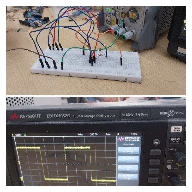
555 OSCILLATOR
Objective: The objective of this task was to design and test a 555 timer IC configured as an astable multivibrator with a duty cycle of 60%. This involved selecting appropriate resistor and capacitor values, setting up the circuit on a breadboard, and observing the output waveform using a Digital Storage Oscilloscope (DSO).
Methodology:
Component Selection:
555 Timer IC: Chosen for its versatility in generating square wave oscillations. Resistors: Selected R1 = 6.8kΩ and R2 = 10kΩ to achieve the desired duty cycle. Capacitor: Chose C = 10µF to set the frequency of oscillation. Circuit Design:
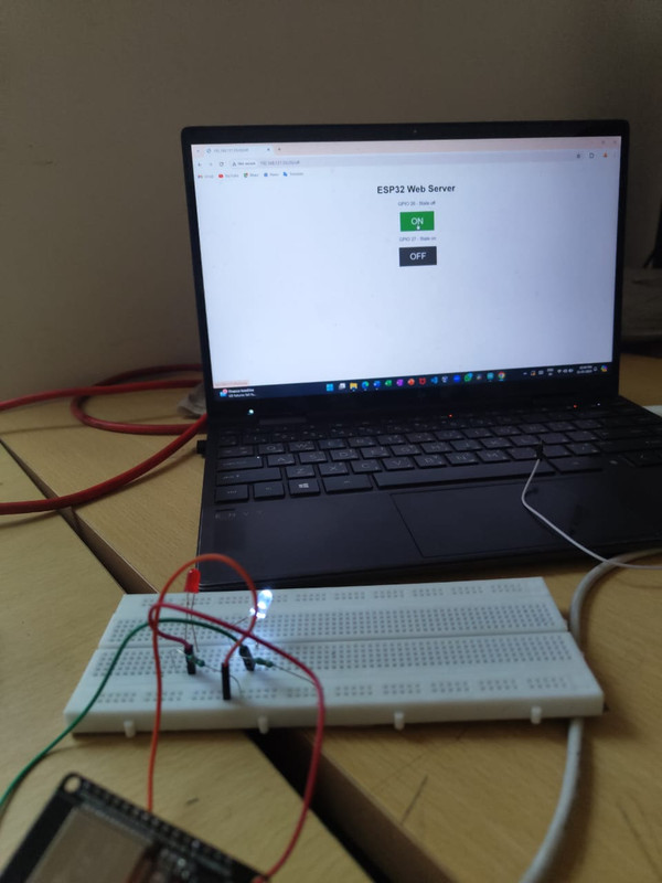
TASK:LED TOGGLE USING ESP32
Objective: The objective of this project was to utilize an ESP32 microcontroller to create a standalone web server capable of controlling an LED connected to its GPIO pin. This involved setting up the hardware components, writing the Arduino sketch in the Arduino IDE, uploading the program to the ESP32, and testing the functionality through a web interface.
Hardware Components Used:
- ESP32 Development Board: Utilized for its built-in Wi-Fi capabilities and GPIO pins suitable for controlling peripherals like LEDs.
- LED: Basic light-emitting diode used as a visual indicator.
- Resistor: Current-limiting resistor (usually 220Ω to 1kΩ) to protect the LED.
- Breadboard and Jumper Wires: Used for easy prototyping and connecting components.
- USB Cable: To connect the ESP32 board to the computer for programming and power.
Methodology:
-
Setting up the Circuit:
- Connected an LED and a current-limiting resistor in series.
- Connected the LED/resistor circuit to a GPIO pin on the ESP32 (e.g., GPIO 2).
-
Writing the Arduino Sketch:
- Used the Arduino IDE with ESP32 board support installed.
- Developed an Arduino sketch to configure the ESP32 as a web server.
- Implemented HTTP GET requests to control the LED: turning it ON and OFF via web links.
-
Uploading the Program:
- Selected the appropriate ESP32 board and COM port in the Arduino IDE.
- Uploaded the compiled sketch to the ESP32 development board via USB cable.
- Monitored the upload process and verified successful completion.
-
Testing and Verification:
- Opened the Serial Monitor in Arduino IDE to monitor ESP32's connection to Wi-Fi and obtain its IP address.
- Accessed the IP address of the ESP32 from a web browser on a computer or smartphone.
- Interacted with the web server interface to toggle the LED ON and OFF.
- Verified the functionality of controlling the LED remotely through the web interface.
Results and Analysis:
- Functionality: Successfully implemented a web server on the ESP32 that allowed remote control of an LED via a web browser.
- User Interface: The web interface provided simple links (e.g., "/on", "/off") to toggle the LED state, demonstrating basic interaction capabilities.
- Reliability: The ESP32 maintained stable operation throughout the testing phase, responding promptly to requests and reliably controlling the LED.
Conclusion:
This project highlighted the versatility of the ESP32 microcontroller in IoT applications, showcasing its ability to serve web pages and handle HTTP requests for controlling physical devices. By integrating hardware components with software development in the Arduino IDE, we achieved a practical example of IoT device control via a web interface.
TASK 06: Karnaugh Maps and Deriving the logic circuit
1. Define the Conditions
Let's define the conditions based on the states:
- DDD: Door state (1 for open, 0 for closed)
- KKK: Key state (1 for pressed, 0 for not pressed)
- AAA: Alarm output (1 for activated, 0 for not activated)
2. Determine Alarm Conditions
The alarm should activate (output A=1A = 1A=1) under the condition:
- Door is open and key is not pressed: D=1ANDK=0D = 1 \quad \text{AND} \quad K = 0D=1ANDK=0
3. Simplify Using AND Gates
To implement this using AND gates, we can directly use two AND gates:
-
AND Gate 1: Takes inputs DDD and Kˉ\bar{K}Kˉ (where Kˉ\bar{K}Kˉ is the complement of KKK, i.e., Kˉ=K′\bar{K} = K'Kˉ=K′).
- Output = D⋅KˉD \cdot \bar{K}D⋅Kˉ
-
AND Gate 2: Takes the output of the first AND gate and an additional control input (this can be set to 1, essentially acting as a buffer or direct input depending on the circuit design).
- Output = D⋅KˉD \cdot \bar{K}D⋅Kˉ
4. Circuit Design
Connect the AND gates as follows:
-
AND Gate 1: Inputs DDD and Kˉ\bar{K}Kˉ
-
AND Gate 2: Inputs the output of AND Gate 1 and another control input (can be a direct input or from another AND gate, depending on the specific circuit design).
-
Output Device: Buzzer or LED connected to the output of AND Gate 2.
Explanation:
- AND Gate 1: Produces D⋅KˉD \cdot \bar{K}D⋅Kˉ, which is true only when D=1D = 1D=1 and K=0K = 0K=0.
- AND Gate 2: Further refines the condition or directly passes the output from AND Gate 1 to the alarm output.
- The output device (buzzer or LED) is activated when both AND gates output a logic high (1), indicating the desired alarm condition is met.
Conclusion:
This circuit design effectively implements the burglar alarm system using only AND gates, adhering to the specified conditions of door state and key press status. It ensures simplicity and reliability in operation, leveraging basic logic gates to achieve the desired functionality.
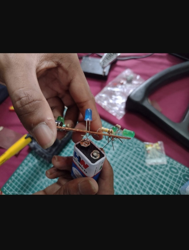
###Task 7: Soldering Prerequisites Procedure
- Introduction to Equipment The coordinator provided an overview of each tool, explaining their functions and safety measures.
- LED Circuit Soldering A simple LED circuit on a perf board was chosen for practice. Components included resistors, an LED, and connecting wires.
- Soldering Process Tinning the Soldering Iron: Applied a small amount of solder to the iron tip to ensure better heat transfer. Preparing Components: Trimmed excess leads from components for a clean assembly. Applying Flux: A small amount of flux was applied to the solder joints to enhance soldering. Soldering Components: Connected the components on the perf board, soldering one joint at a time, ensured a secure and neat solder joint.