
11 / 10 / 2026
TASK 1 UAV Assembly & Flight Controller Configuration
1. Project Overview & Objectives
- Objective: Collaboratively assemble, wire, and configure a fully functional quadcopter integrated with GPS, an ExpressLRS (ELRS) radio receiver, and an ArduPilot-compatible flight controller.
- Scope: Mechanical assembly, power distribution, electronic speed controller (ESC) calibration, radio binding (Radiomaster TX16S & RP1), telemetry setup via Mission Planner, and comprehensive sensor calibration.
3. Bill of Materials (BOM)
- Frame: Carbon fiber quadcopter frame (e.g., F450 or equivalent).
- Flight Controller (FC): ArduPilot-supported flight controller board (e.g., Pixhawk or Matek).
- Radio System: Radiomaster TX16S transmitter paired with a Radiomaster RP1 (ELRS) receiver.
- Propulsion System: Brushless DC motors, Electronic Speed Controllers (ESCs), and matched propellers.
- Navigation Module: GPS + Compass module (e.g., M8N / M10 series).
- Power System: LiPo battery and power module for real-time voltage and current sensing.
4. Step-by-Step Assembly & Wiring Procedure
Step A: Mechanical Assembly & Power Distribution
- Securely mount the brushless motors to the carbon fiber frame arms using threadlocker (Loctite) on all metal screws to prevent vibration-induced loosening.
- Solder the ESC power leads to the Power Distribution Board (PDB) or battery leads, ensuring correct polarity ($+$ and $-$). Connect the three motor phase wires to the ESC outputs (any two can be swapped later if motor rotation direction needs reversal).
Step B: Flight Controller Mounting & Vibration Isolation
- Mount the flight controller near the exact center of gravity of the quadcopter frame using anti-vibration dampening double-sided tape or silicone mounts.
- Route all signal and power wires cleanly away from high-current ESC wires to minimize electromagnetic interference (EMI)
5. Radio Transmitter & Receiver Binding (Radiomaster TX16S & RP1)
- Firmware Sync: Ensure both the Radiomaster TX16S internal/external ELRS module and the RP1 receiver are flashed with compatible ExpressLRS major firmware versions.
- Binding Procedure: Power the receiver on and off three times (or use the ExpressLRS Lua script on the TX16S) to enter bind mode, confirming solid LED status upon successful handshake.
- Channel Mapping: Configure transmitter channels in EdgeTX/OpenTX on the TX16S using the standard AETR (Aileron, Elevator, Throttle, Rudder) mapping.
6. Mission Planner Setup & Firmware Flashing
- Connection: Connect the flight controller to the ground station laptop via a secure USB cable. Open Mission Planner, select the correct COM port, and set the baud rate to
115200. - Firmware Installation: Navigate to the Initial Setup > Install Firmware tab and select ArduCopter to flash the latest stable firmware matching your hardware board.
- Frame Type Selection: Define the multirotor frame class (Quad) and exact motor layout geometry.
7. Sensor Calibration
- Accelerometer Calibration: Perform the standard 6-point calibration routine in Mission Planner (Level, Left, Right, Nose Down, Nose Up, Back) ensuring the drone is held steady at each orientation.
- Compass Calibration: Execute the live calibration routine, rotating the quadcopter smoothly across all axes until green completion bars appear and offsets are saved.
- Radio Calibration: Verify that stick inputs on the TX16S map correctly from $1000\text{ }\mu\text{s}$ to $2000\text{ }\mu\text{s}$ with center trims at $1500\text{ }\mu\text{s}$.
TASK 3 Introduction to MATLAB :
Objective : To gain foundational knowledge of MATLAB and Simulink.
Learnings and Outcomes :
I have learnt the basics of MATLAB.

 \
\
TASK 4 Advanced PID Tuning :
1. Executive Summary & PID Fundamentals
A Proportional-Integral-Derivative (PID) controller is a control loop feedback mechanism widely used in industrial control systems and autonomous vehicles. It continuously calculates an error value as the difference between a desired setpoint r(t) and a measured process variable y(t), and applies a correction based on proportional, integral, and derivative terms.
2. Learnings from Video Resources (PID in Depth)
Based on reviewing the core PID resource playlist, the breakdown of each tuning parameter is as follows:
- Proportional (P):
- Function: Reacts directly to the current error.
- Effect: Reduces the rise time and steady-state error. However, setting P too high leads to aggressive oscillations, system overshoot, and instability.
- Integral (I):
- Function: Accumulates the error over time.
- Effect: Eliminates steady-state errors (such as persistent wind drift or imbalances). Too much I, however, causes slow oscillations, phase lag, and integrator windup.
- Derivative (D):
- Function: Predicts future error by evaluating the rate of change.
- Effect: Acts as a damper to smooth out system response, reduce overshoot, and improve transient stability. High $D$ values amplify high-frequency sensor noise
3. UAV Mission Planner PID Configuration
Connecting a UAV flight controller to Mission Planner allows monitoring and modifying the stabilization loop parameters:
| Axis | Proportional (P) | Integral (I) | Derivative (D) | Description & Observations |
|---|---|---|---|---|
| Roll | 0.135 | 0.135 | 0.0036 | Manages lateral stabilization; reacts immediately to rolling disturbances. |
| Pitch | 0.135 | 0.135 | 0.0036 | Manages longitudinal tilt; mirrors Roll performance on symmetric frames. |
| Yaw | 0.200 | 0.020 | 0.0000 | Controls heading rotation; typically requires lower damping due to rotational inertia. |
4. Self-Balancing Car Implementation
A two-wheeled self-balancing robot was built to validate PID principles in hardware:
- Sensor Fusion: An MPU6050 IMU combines accelerometer data (gravity reference) and gyroscope data (rotation rate) via a complementary filter to determine the precise tilt angle.
- Control Loop: Operating at a consistent loop frequency (e.g., every 10 milliseconds), the microcontroller calculates the PID output based on the tilt angle error.
- Actuation: The computed control output adjusts the PWM signals sent to the motor driver, driving the wheels forward or backward to counteract the falling motion and maintain balance.
5. Experimental Tuning Observations
Tuning the system iteratively using manual trial-and-error yielded the following practical behaviors:
- Tuning P Independently: Setting I=0 and D=0 and raising $P$ caused the robot to rapidly twitch and oscillate back and forth across the balance point without stopping.
- Adding D Damping: Introducing the D term successfully dampened the rapid oscillations, stabilizing the snapping movements and bringing the system to a smooth equilibrium.
- Adding I Correction: Adding a small amount of I eliminated slight steady-state leaning biases caused by uneven weight distribution, whereas an excessive I value caused slow, growing oscillations.
TASK 5 RULES IN THE RULE BOOK WRITTEN BY BLOOD :
Objective :
- Take an example of a previous Air Crash from Wyngx or any other source of your choice.
- Write a detailed report of the air crash investigation, the report should include:
- Details of the flight, place, time, pilot details and an introductory paragraph about the accident which occurred /was about to occur including the losses occurred.
- Explain in brief about the aircraft.
- Using the Swiss Cheese Model analyze the key contributing factors (technical, human, environmental etc.) and also explain how each of these factors (layers of the Swiss Cheese) accelerated the accident when aligned together.
- State the various theories and assumptions which took place during the investigation and also mention the reasons which led to the elimination/confirmation of these theories.
- Reflect on what lessons were learned and how aviation standards changed post accident.
Learnings and Outcomes :
I reported on the Crash of Air India flight 171, which crashed on the Ahmedabad Airport on June 12, 2025.
Click Here to view my Air Crash Investigation Report.
The final official investigation report for AIT INDIA FLIGHT 171 is not yet been released.
References :
AIR CRASH INVESTIGATION VIDEO\
TASK 6 Flight Data Logging & Analysis :
Objective :
To explore the methodology behind air crash investigations and learn how aviation safety evolves from past incidents.\
- Extract log files from a Pixhawk/APM flight controller.\
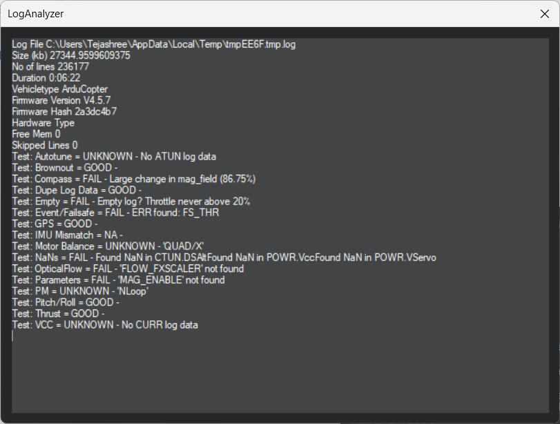
- Analyze flight stability, GPS accuracy, battery performance using Mission Planner.\
- Generate graphs for:
Altitude vs time. Throttle & Battery vs time consumption. Velocity vs time
Learnings and Outcomes :
1.Crash Log :\
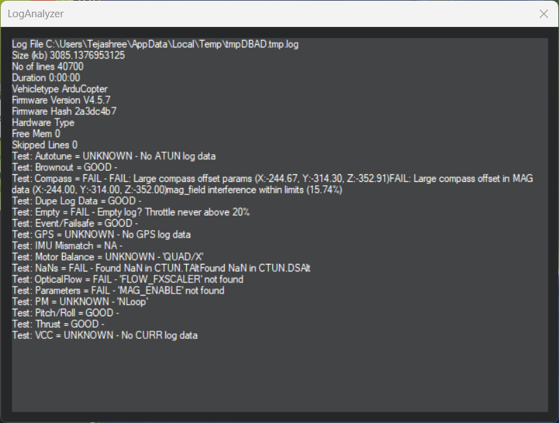
- Crash Auto Log:
 \
\ - Altitude vs Time:
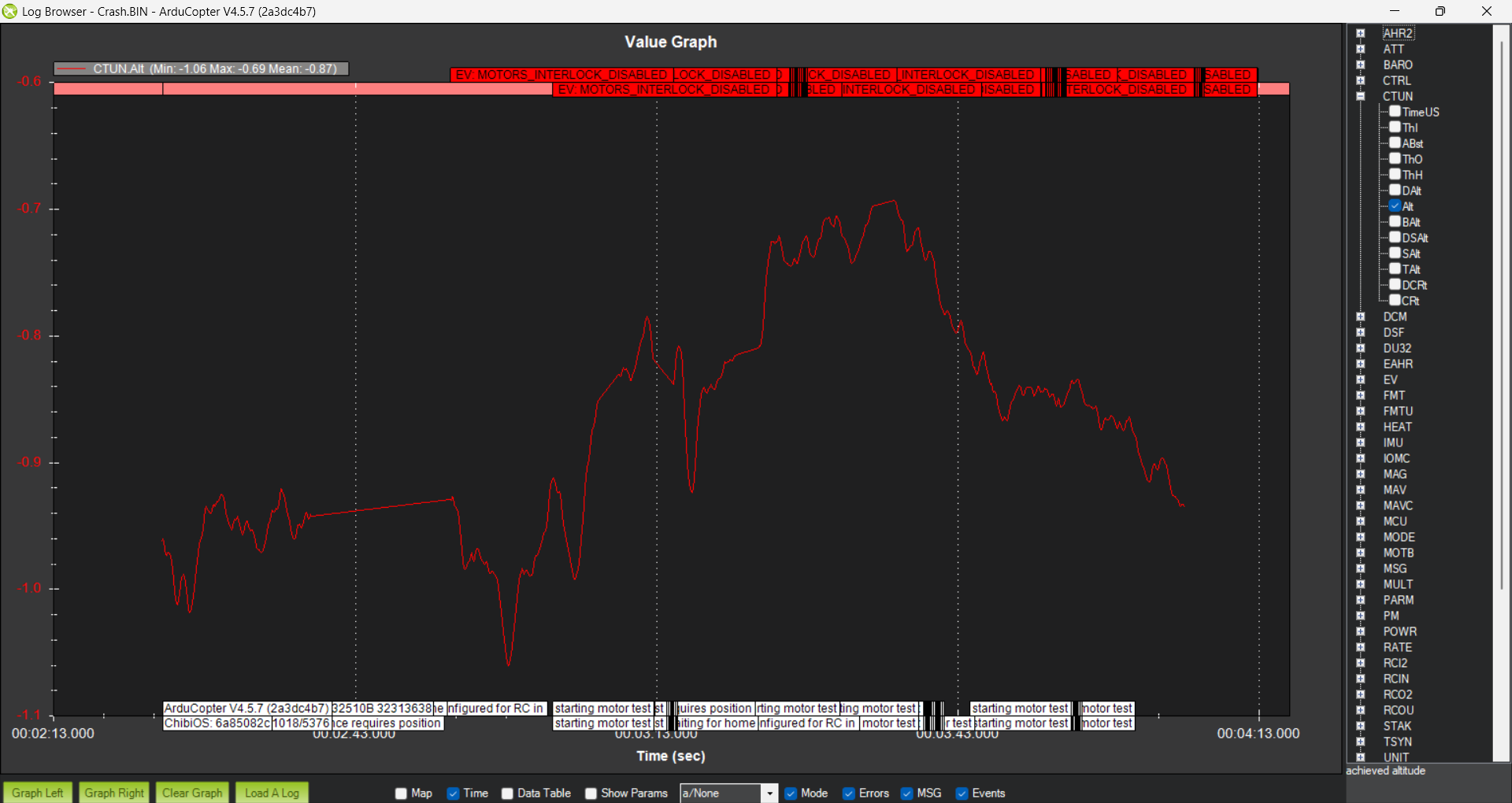
This graph shows that the altitude remains below zero throughout the log.
The vehicle never gains positive altitude, indicating no successful takeoff.
Small fluctuations suggest minor throttle inputs or sensor noise while staying on the ground.
This behavior is consistent with a failed takeoff or crash shortly after arming.
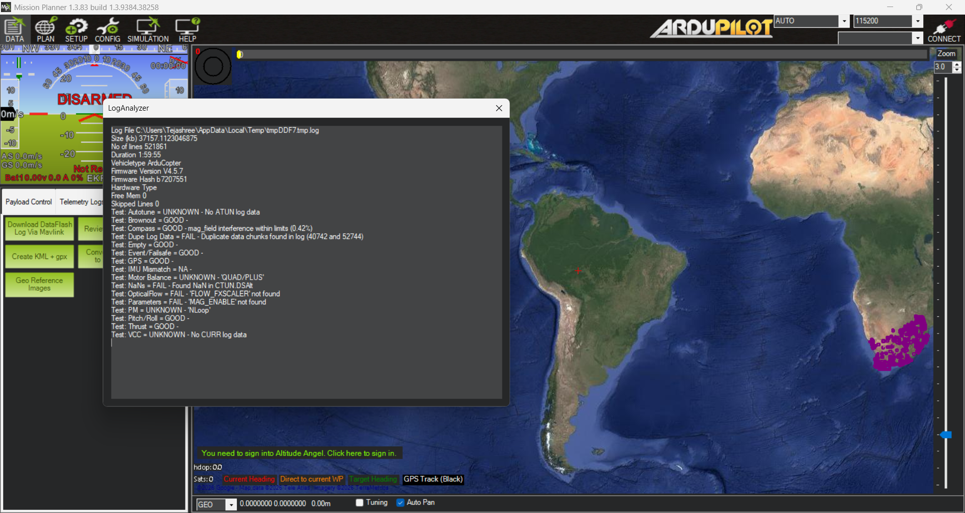
2.Simulator Log :\ - Simulator Auto Log
 \
\ - Altitude vs Time:
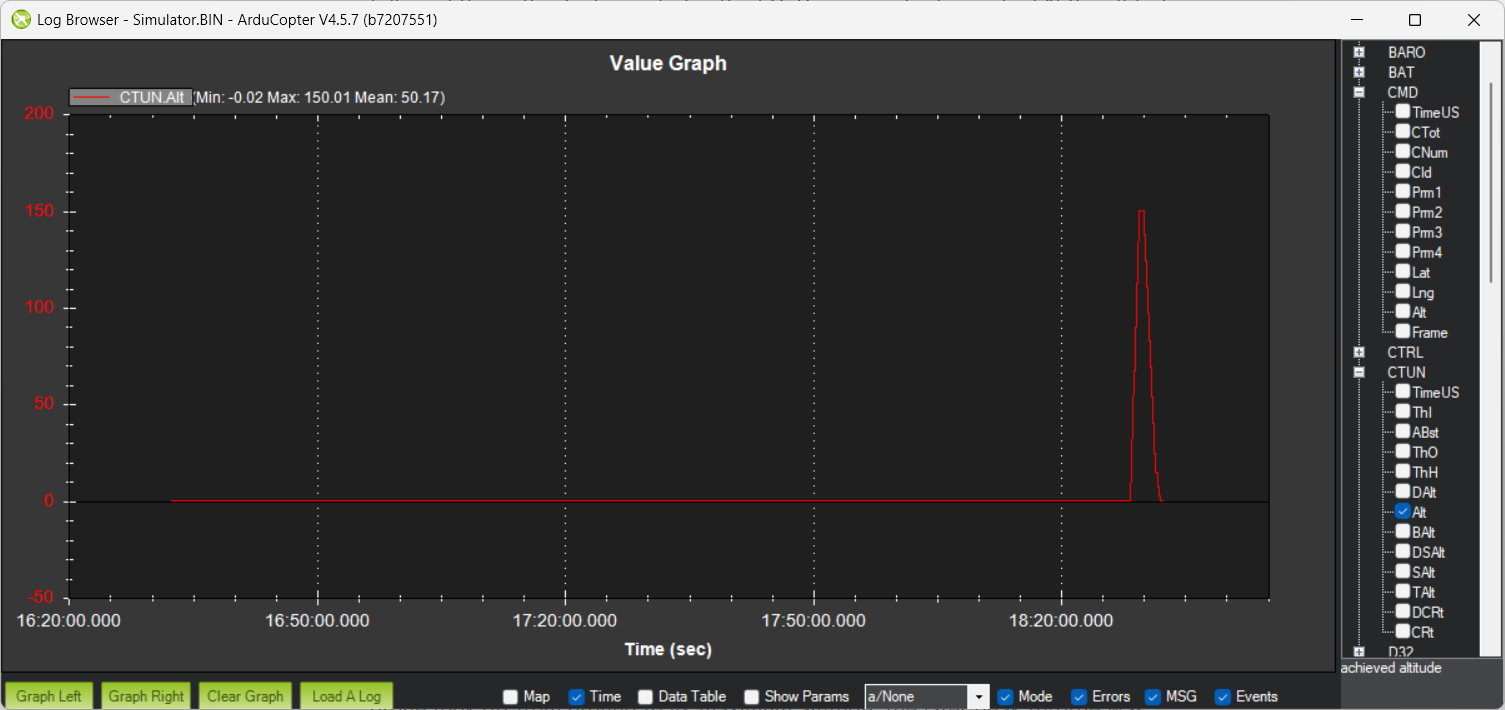
This graph shows the altitude used by the flight controller for control. The altitude stays near 0 m initially, indicating the vehicle is on the ground, during STABILISE mode. A sharp rise to about 150 m represents the takeoff and rapid climb phase, during AUTO mode. Such a steep change is typical in simulator or auto-mission flights, where altitude is commanded quickly.\ - Throttle vs Time:
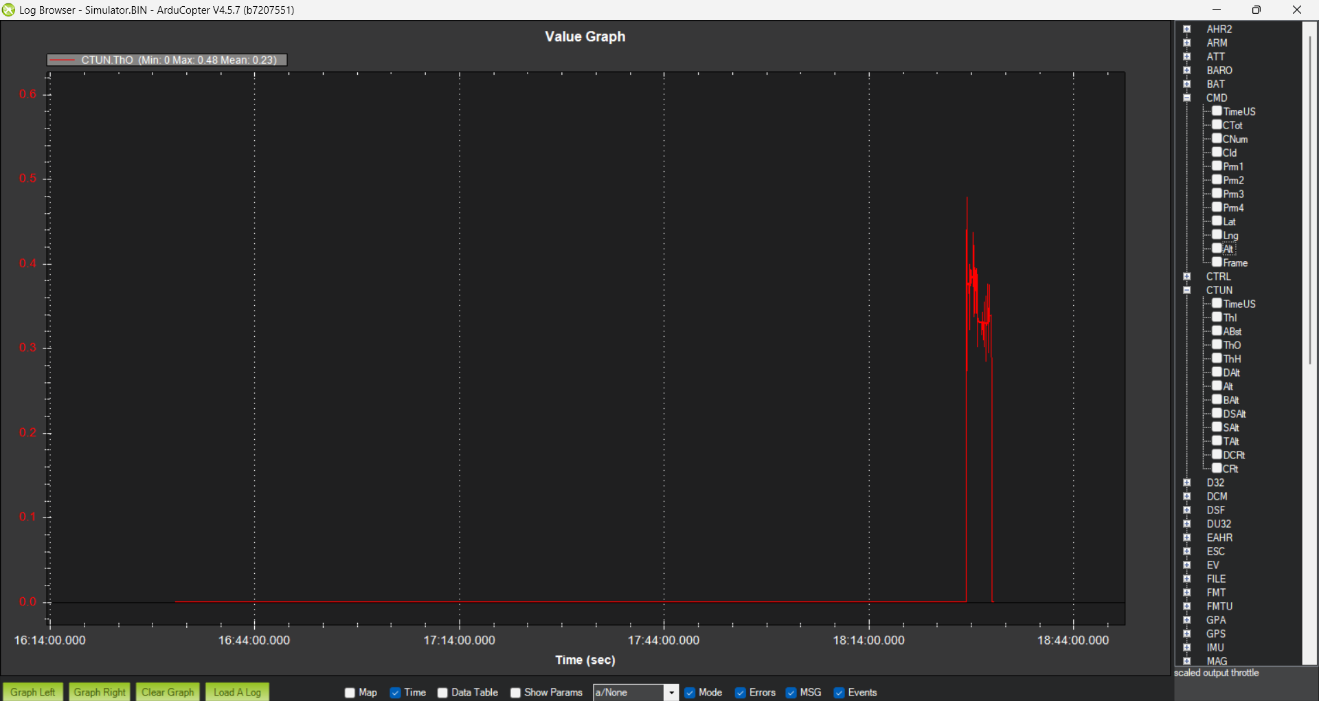
This graph shows the actual throttle output commanded by the flight controller. The throttle remains near 0 initially, indicating the vehicle is on the ground or disarmed. A sharp rise to about 0.45–0.48 corresponds to takeoff and climb, where higher throttle is required.\ - Battery Consumption vs Time :
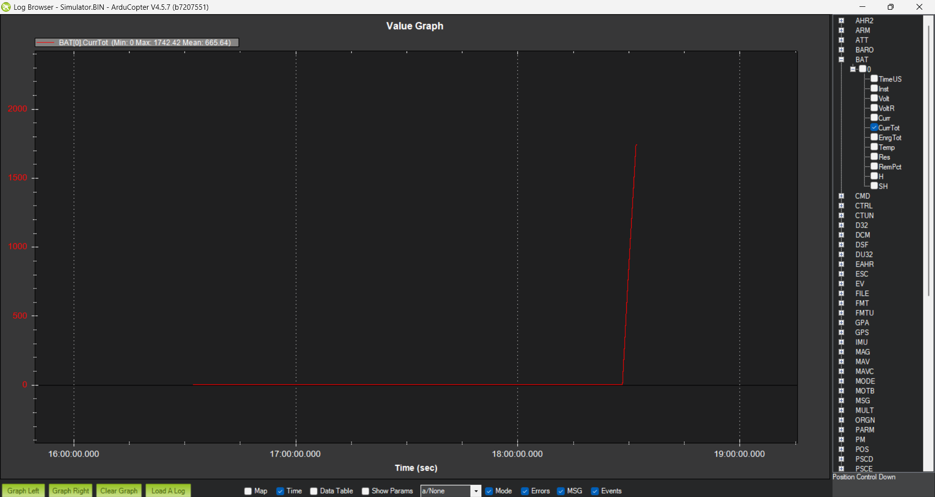
This graph shows the total battery capacity consumed (in mAh) since arming. The flat line at the start indicates no power draw while the vehicle is on the ground. The sharp upward rise corresponds to takeoff and active flight, where current is being drawn continuously. The final value (~1740 mAh) represents the total energy used during the flight.\
- AMS Log :
- Auto Log :
 \
\ - Altitude vs Time
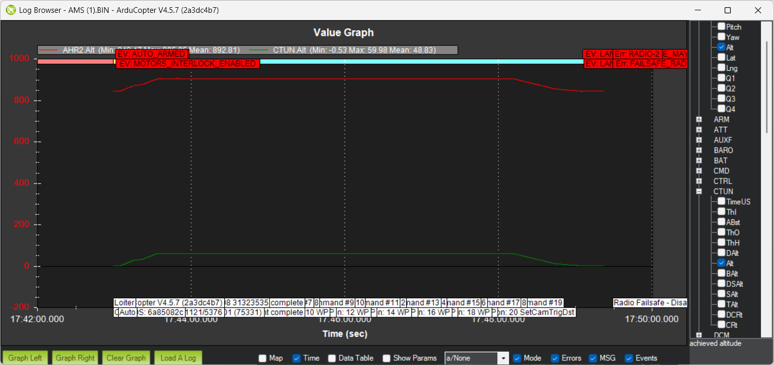
A stable altitude curve indicates good vertical control and sensor reliability.
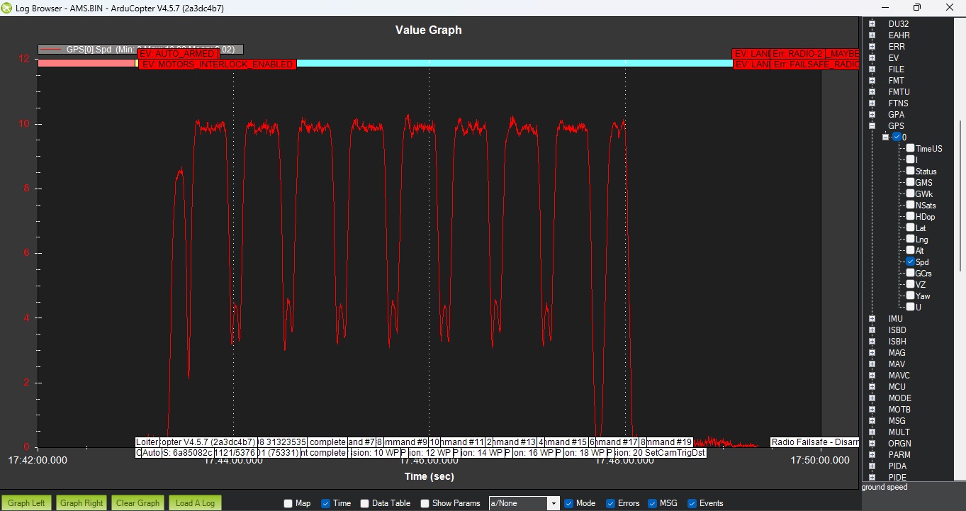
Consistent velocity indicates predictable flight dynamics.\
TASK 7 Introduction to ROS 2 for UAVs :
Objective :
To get started with the Robot Operating System (ROS) 2 ecosystem and understand its application in UAV communication through node-based architecture.
Learnings and Outcomes :
Document of every step of this task is below with screenshorts :
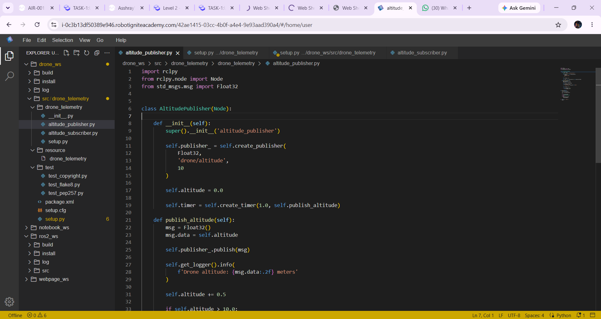 Publisher code
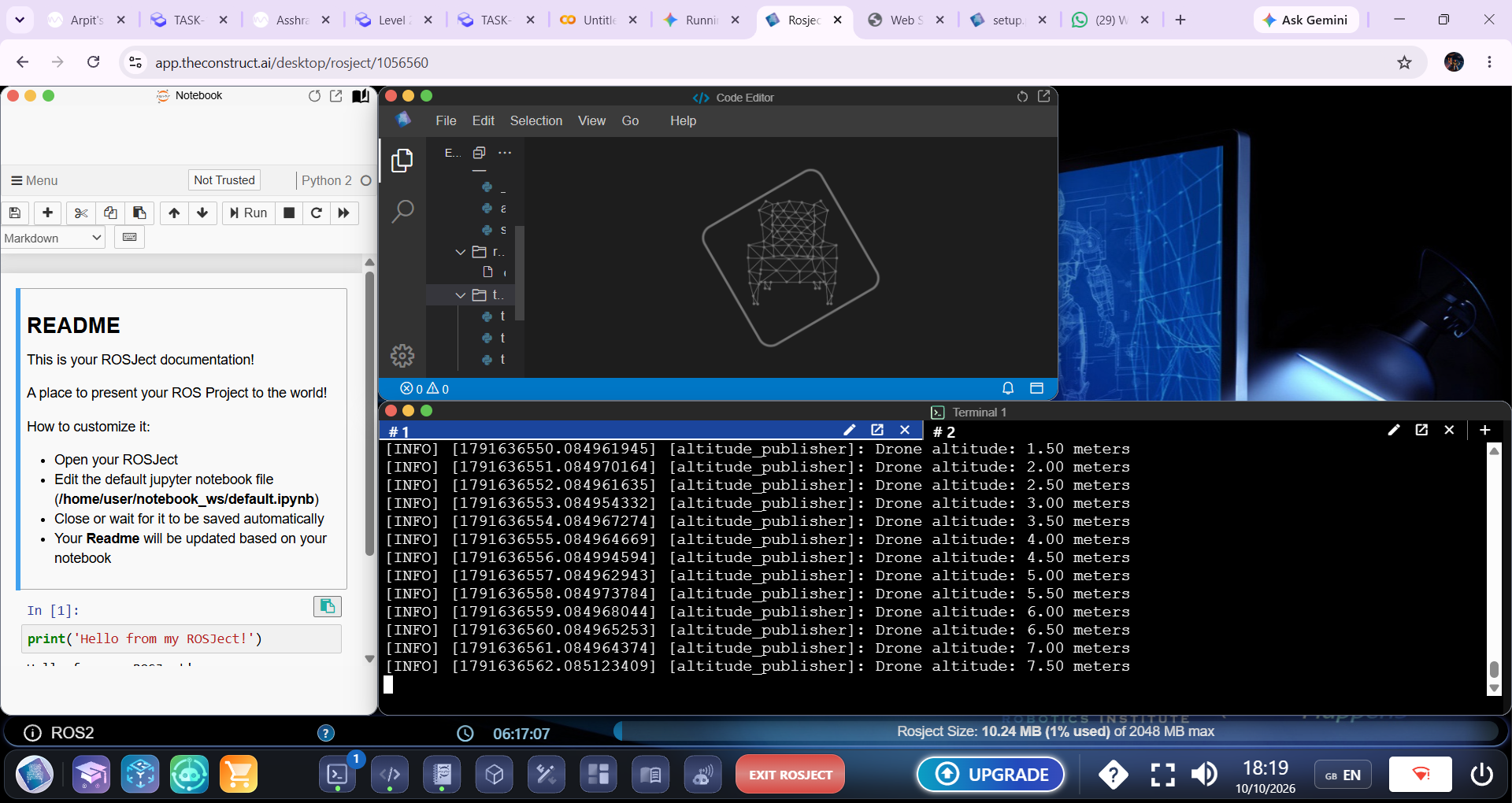 Publisher output
 setup code
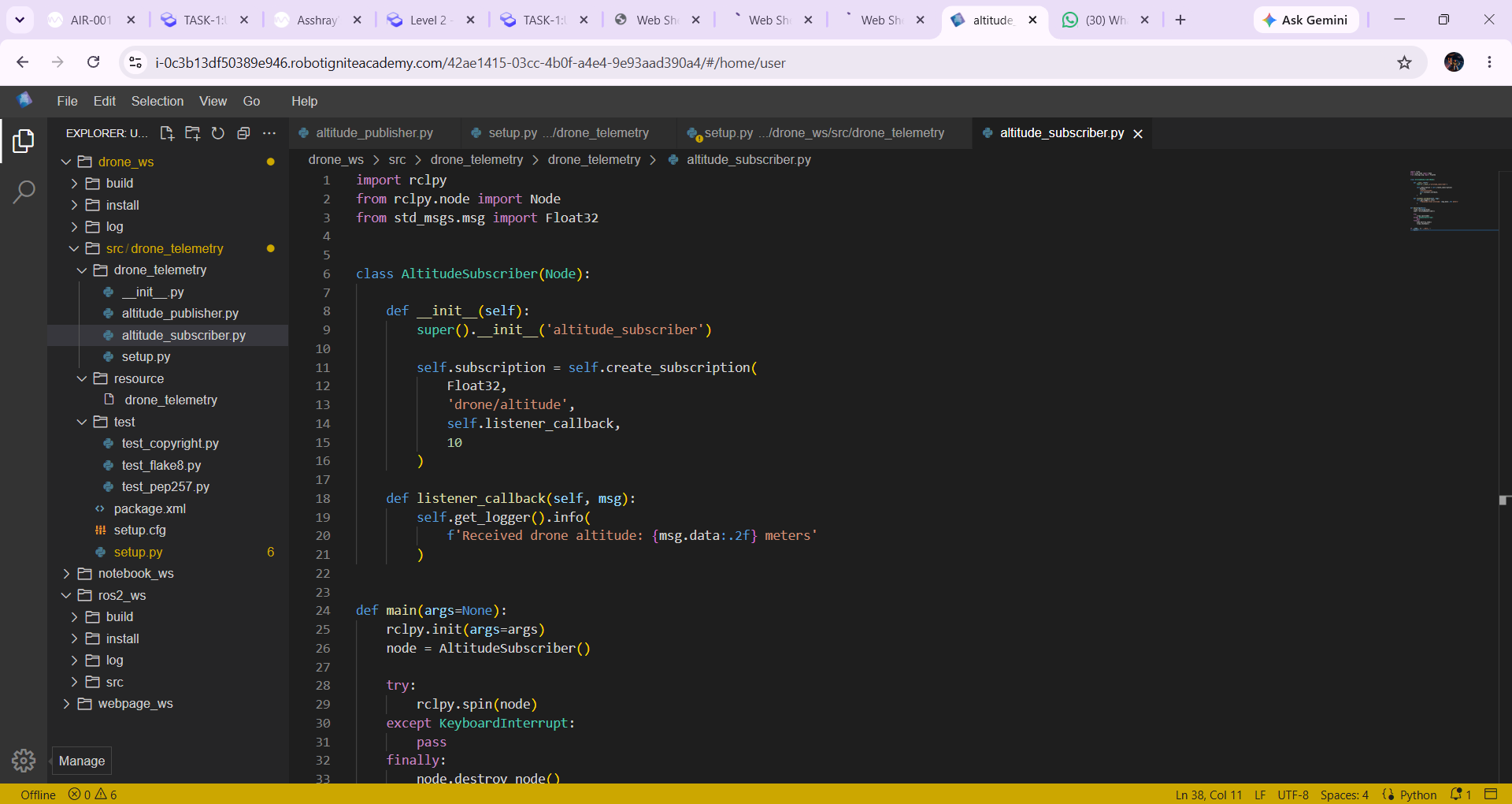 Suscriber code
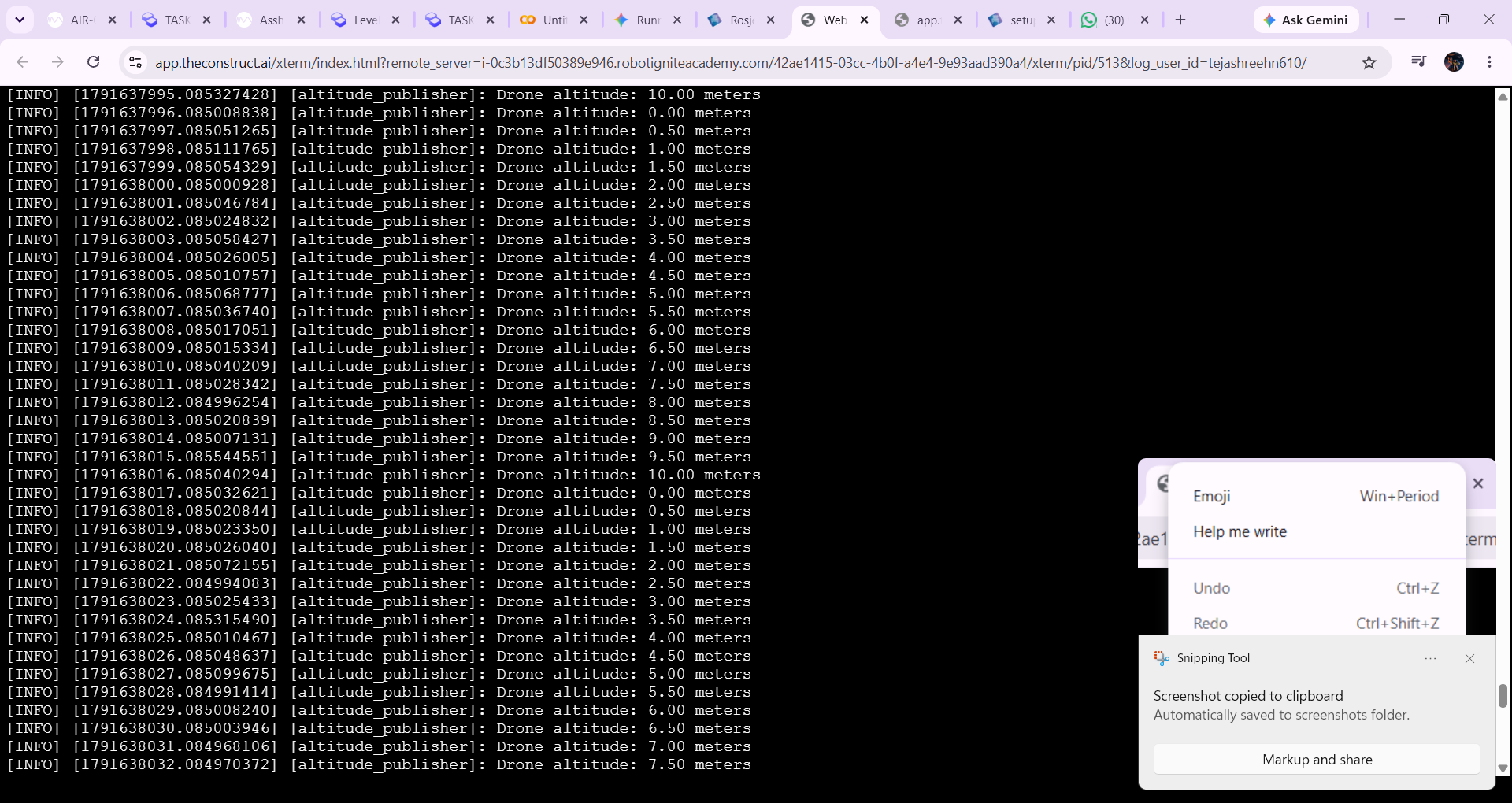 Suscriber output
click here to view my R0S 2 documentation.\