
27 / 2 / 2026
TASK 1 INTRODUCTION TO AERODYNAMICS AND AIRCRAFT STRUCTURES :
Objective :
1.Understand Bernoulli's Principle, Newton's Third Law, and aerodynamic forces.
2.Explain lift, drag, thrust, weight, and aircraft stability.
3.Learn about primary and secondary control surfaces.
4.Study basic components like the pitot tube and radio altimeter.
Learnings and Outcomes :
BERNOULLI'S PRINCIPLE IN AVIATION :
Bernoulli's Principle states: Fast-moving air has low pressure, and slow-moving air has high pressure.
This principle is the magic behind how an airplane wing generates lift, the force that pushes the plane up.
Significance in Aircraft lift
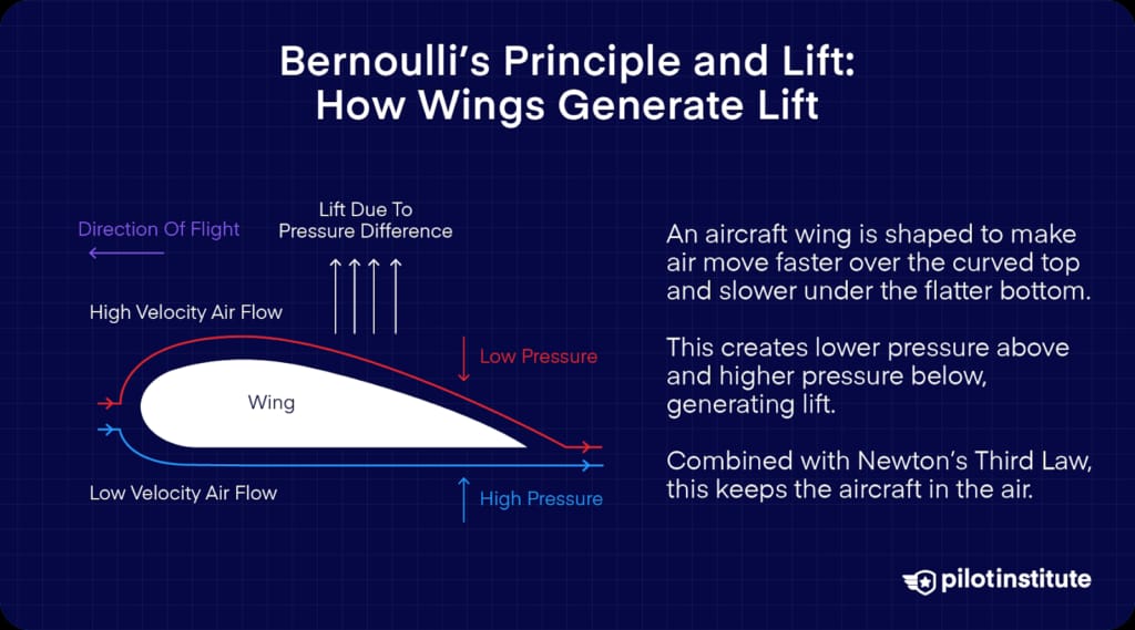
The significance of Bernoulli's Principle is that it explains the fundamental pressure difference that, along with Newton's 3rd Law, creates the necessary lift for everything from a massive jumbo jet to a small drone.
NEWTON'S THIRD LAW OF MOTION IN AVIATION :
Newton's 3rd Law of Motion, is stated as "for every action, there is an equal and opposite reaction," is fundamental to understanding how aircraft generate lift and propulsion.
In aviation, this law is crucial for explaining how forces are created to enable flight.
Significance :
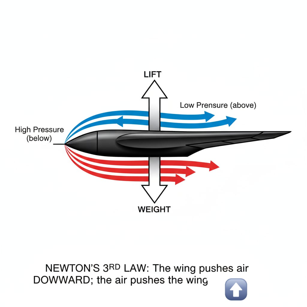
1. Generating Lift:
*Action: An aircraft's wings (or helicopter blades) are designed to push air downwards.
*Reaction: The air, in turn, pushes the wings (or blades) upwards with an equal and opposite force. This upward force is what we call lift, which directly opposes gravity and allows the aircraft to become airborne. The shape of the wing, called an airfoil, is specifically designed to create this downward push of air.
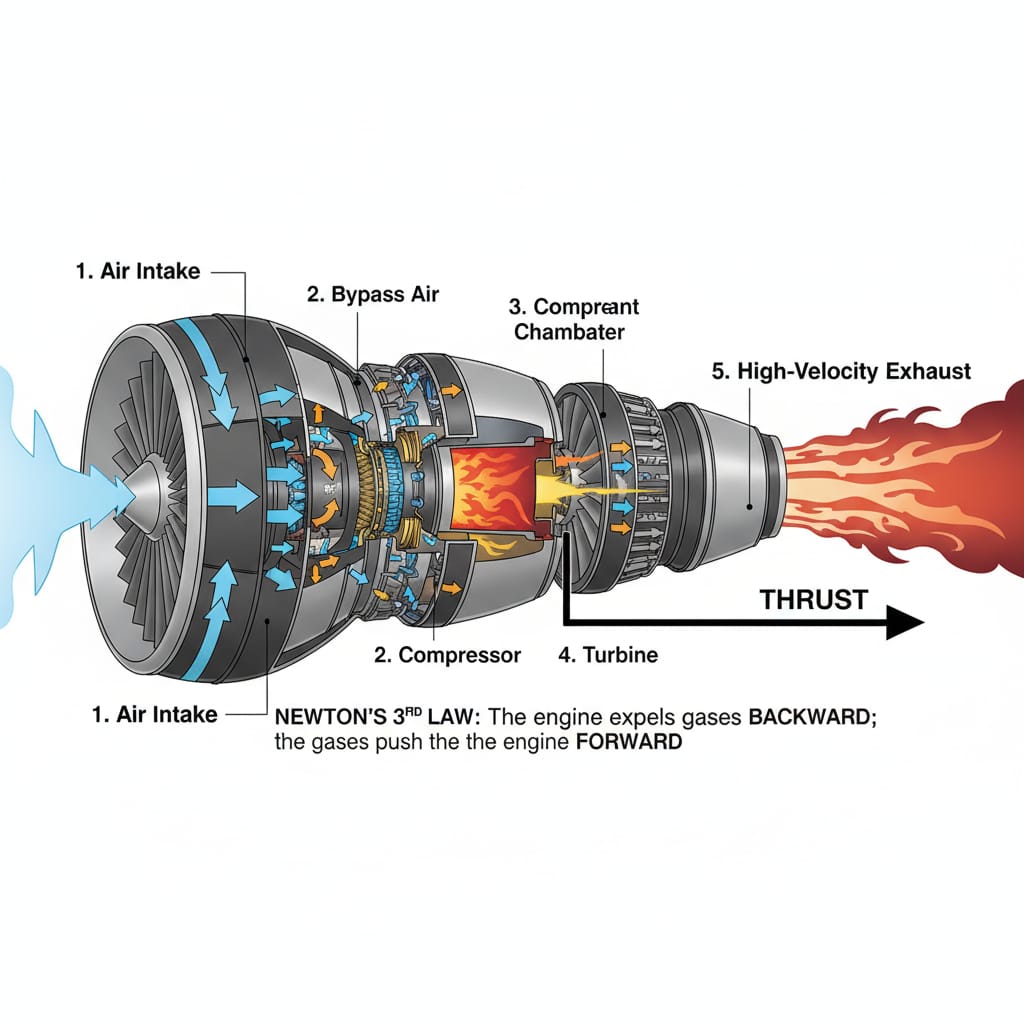
2. Producing Thrust:
*Action: Jet engines and propellers work by expelling a mass of air (or exhaust gases) backward at high velocity.
*Reaction: The expelled air/gases push the engine and, consequently, the entire aircraft forward with an equal and opposite force. This forward force is known as thrust, which overcomes drag and propels the aircraft through the air.
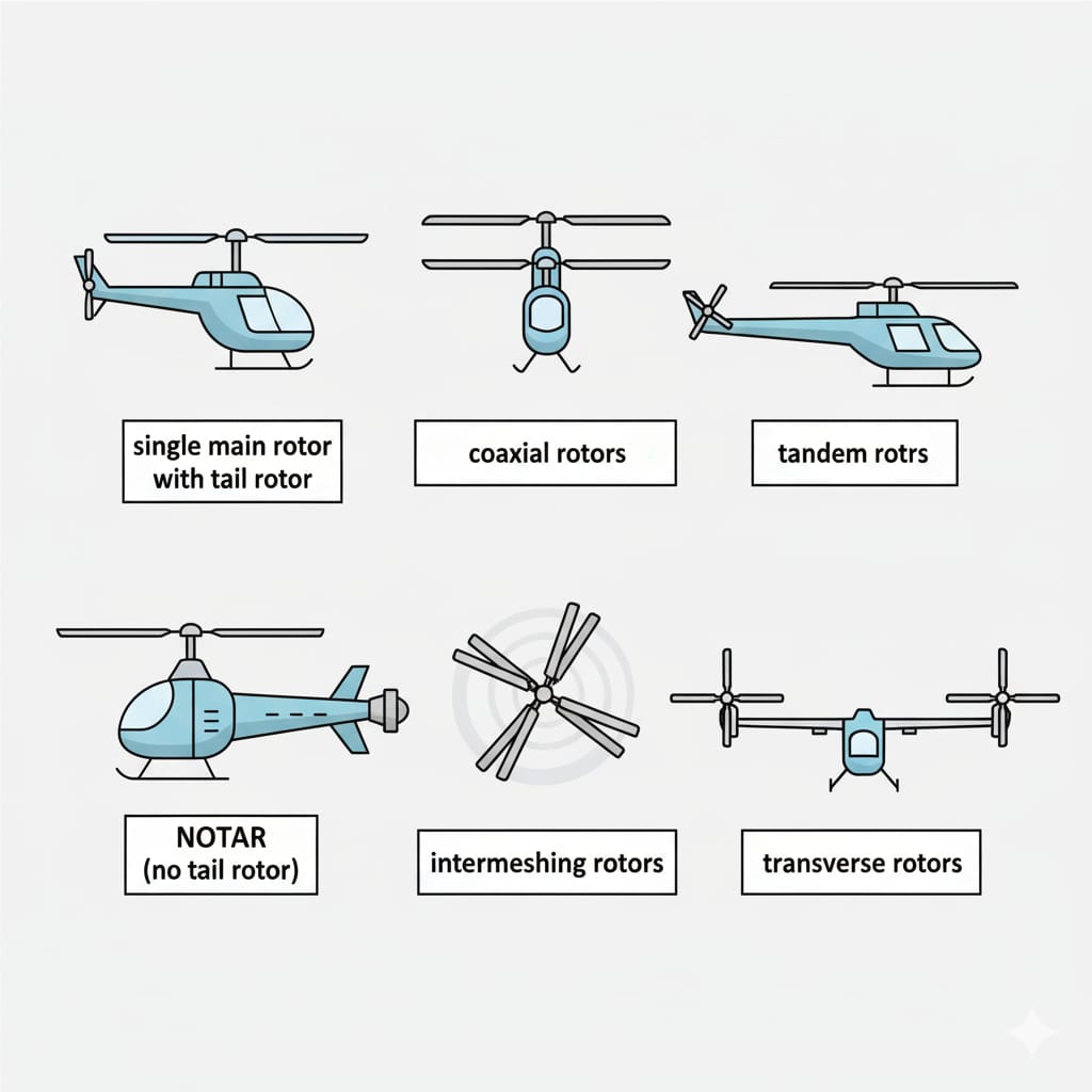
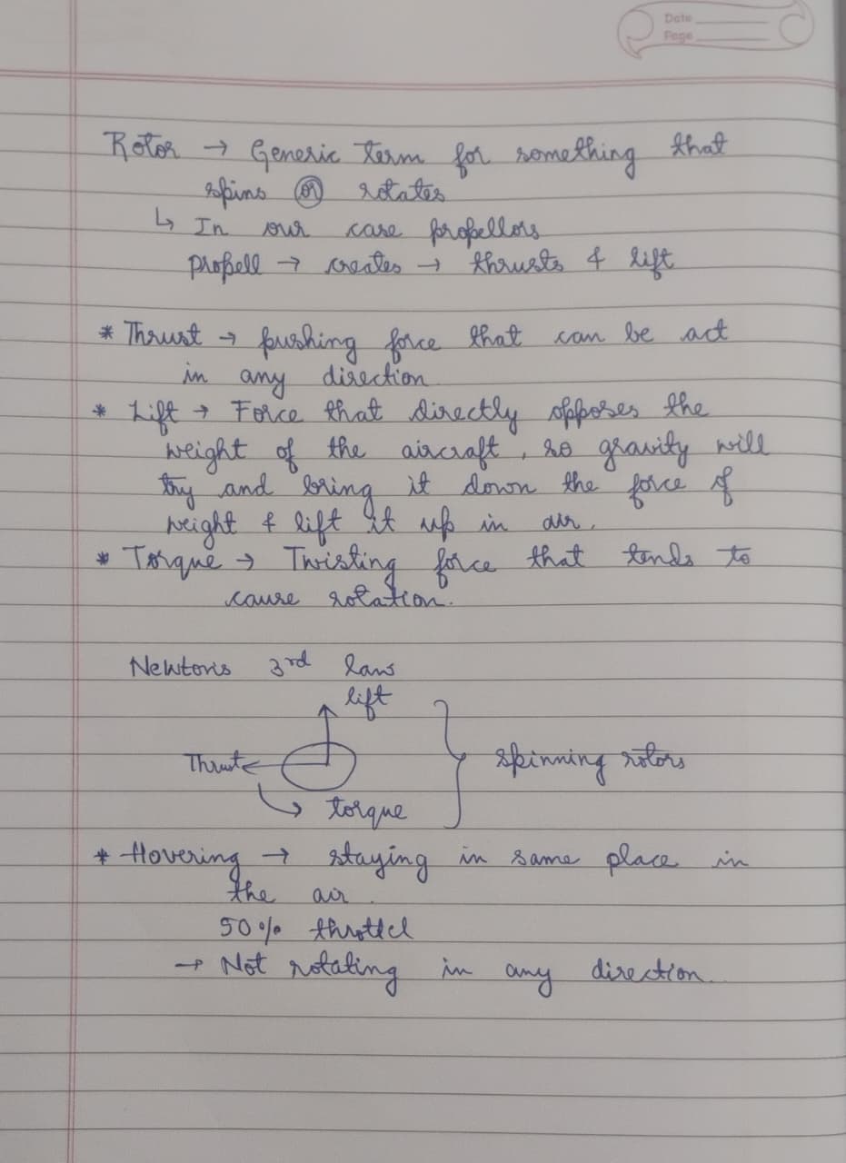
3.Helicopter Anti-Torque Systems:
*Action (Main Rotor): The main rotor blades of a helicopter push a large volume of air downwards to create lift. However, as the blades spin in one direction, they also impart an opposite rotational force (torque) on the helicopter body.
*Reaction (Tail Rotor/Other Systems): To prevent the fuselage from spinning uncontrollably, a tail rotor (or other anti-torque systems like NOTAR, coaxial rotors, etc.) performs an "action" by pushing air sideways. This creates a "reaction" force that counteracts the main rotor's torque, keeping the helicopter stable and allowing it to control its heading (yaw).
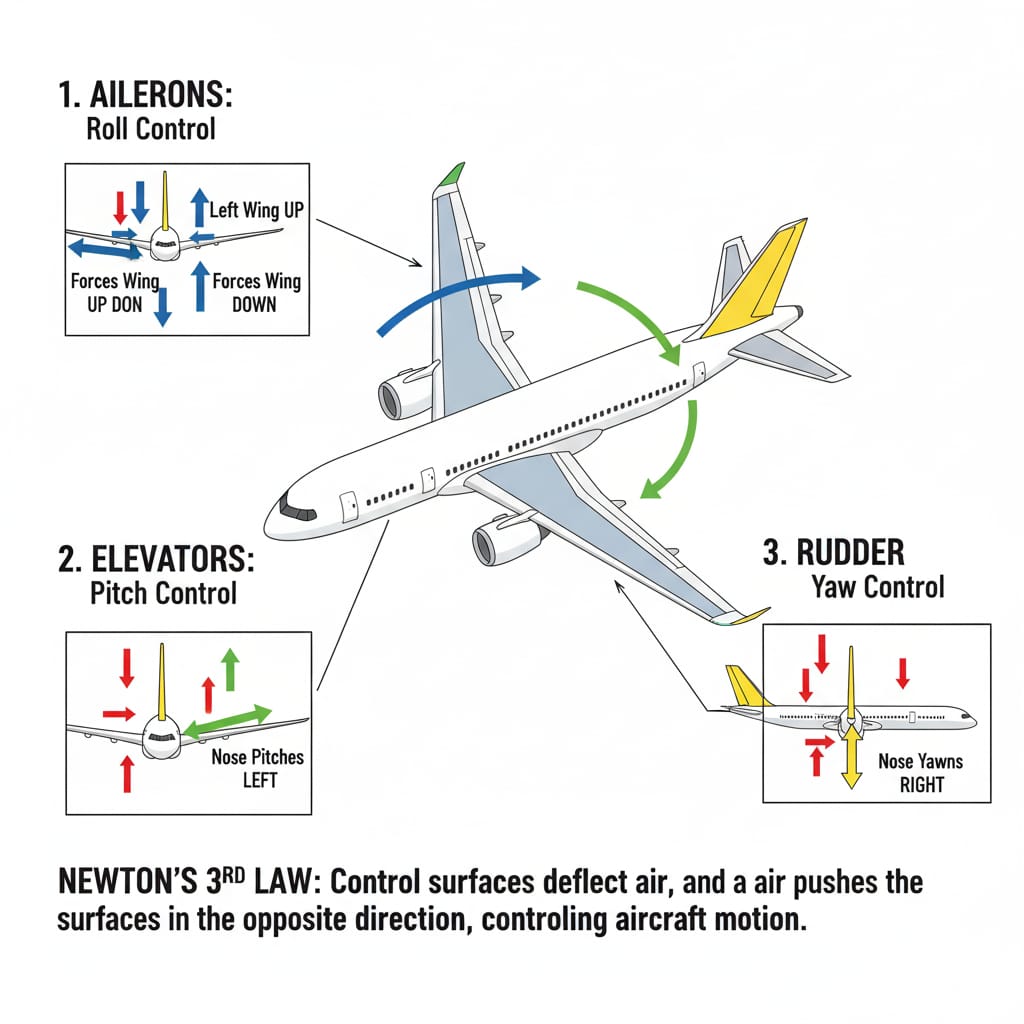
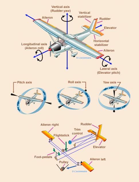
4. Control Surfaces (Ailerons, Elevators, Rudder):
*Action: When a pilot moves a control surface (like an aileron on the wing, an elevator on the horizontal stabilizer, or a rudder on the vertical stabilizer), it deflects the airflow around it.
*Reaction: This deflection of air creates an equal and opposite force on the control surface, which then causes the aircraft to pitch up/down, roll, or yaw. This allows for precise control of the aircraft's attitude and direction of flight
NOTE
Bernoulli: Creates lift by "pulling" the wing up from above (low pressure).
Newton: Creates lift by "pushing" the wing up from below (deflecting air down).
DIFFERENCE BETWEEN UAV & UAS:
UAV (Unmanned Aerial Vehicle) refers to the flying object alone, like the drone.
UAS refer (Unmanned Aerial System) refers to the complete aerial system i.e., it includes the drone, payload, control system etc.
BASICS OF DRONE SCIENCE:
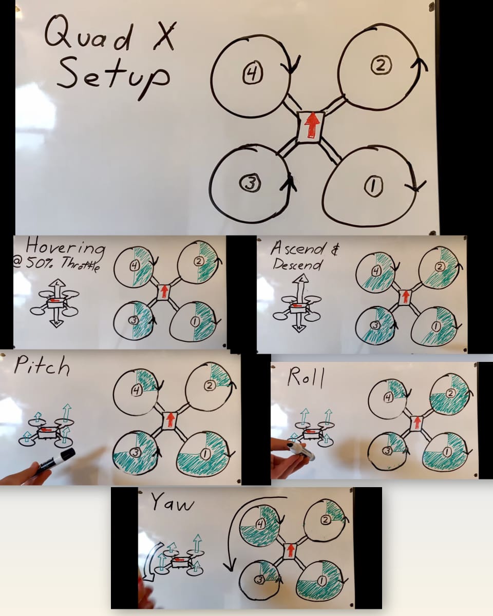
QUAD X FLIGHT DYNAMICS:
DRONE COMPONENTS IN UAS:
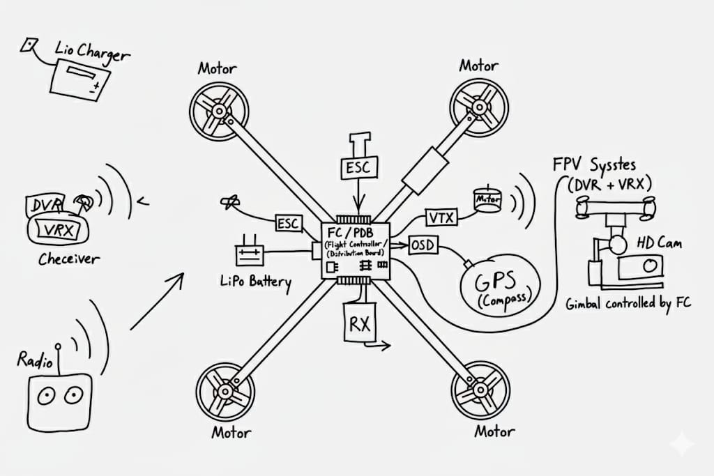
1.Core: The Flight Controller (FC) is the "brain," powered by a LiPo Battery.
2.Propulsion: The FC sends signals to ESCs, which control the speed of the motors.
3.Control: The pilot uses a Radio (TX) to send commands to the drone's Receiver (RX).
4.Navigation: A GPS provides location data, and an OSD overlays flight info onto the video.
5.FPV System: An FPV Camera sends a live video feed via a VTX to the pilot's Goggles.
6.HD Recording: A separate HD Camera, steadied by a Gimbal, records high-quality footage.
SENSOR UNIT:
a. Inertial Measurement Unit (IMU):
It's a sensor system that measures the drone’s orientation, acceleration, and angular velocity. It helps the flight controller understand how the drone is moving and correct its position in real time. The 2 main sensors which fall under IMU are:
Accelerometers: Measures the linear acceleration (linear motion) and force exerted on the drone in X, Y, Z axes.
Accelerometers no not report current speed, they report only the acceleration in a direction.
Gyroscopes: Measure angular velocity (rotational motion) around X, Y, Z axes.
Gyroscopes do not report the current angle, they report only the rate at which the device turns.
b. Barometer:
As the altitude increases the atmospheric pressure decreases, so pressure sensors like barometers help us give information about the altitude of the drone.
FREE BODY DIAGRAM OF INCLINED DRONE:
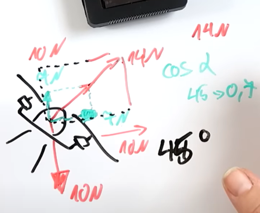
Here, the weight of the drone is 1KG. Therefore, the minimum required thrust being 10 N, the external thrust given by the RC is also 10 N. Since, the drone is inclined at an angle of 45° wrt ground, the vertical component would be 10 Sin 45 = 7 N & horizontal component being 10 Cos 45 = 7 N. Since the 7 N of vertical force isn't sufficient to counteract the 10 N of gravity acting on the drone, the drone won't fly. The minimum required thrust in this case would be 14 N only then the vertical component would get 10 N of force, which is the minimum required force for the drone to hover.
FOUR BASIC FORCES OF AVIATION:
Four physical forces: lift, drag, weight, and thrust.
For flight, an aircraft's lift must balance its weight, and its thrust must exceed its drag. A plane uses its wings for lift and its engines for thrust. Drag is reduced by a plane's smooth shape and its weight is controlled by the materials it is constructed of.
1.Lift (L) is the upward force that opposes weight and is produced mainly by the aircraft’s wings. It is generated because air moves faster over the curved upper surface of the wing and slower below, creating a pressure difference as explained by Bernoulli’s Principle. The lift can be calculated using the formula:

2.Weight (W) is the downward force caused by gravity acting on the aircraft’s mass, given by
W = mg
3.Thrust (T) is the forward force produced by engines or propellers that moves the aircraft through the air. It must overcome drag for acceleration and steady flight.
F=mg
4.Drag (D) is the backward or resisting force caused by air friction and pressure differences around the aircraft body. The drag force is calculated as:

CONCEPT OF LIFT:
Lift is the product of air we're moving through and deflecting it downward.If we deflect more air downward more lift we produce.
FORMULA
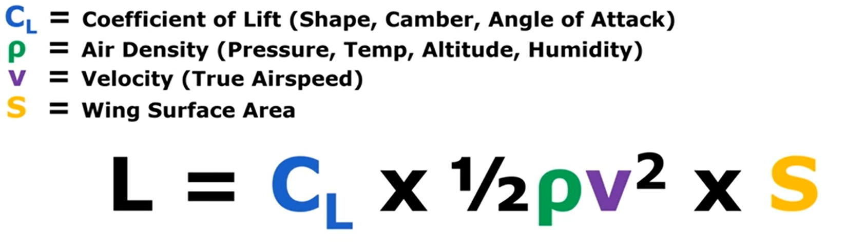
The Four Factors That Create Lift:
C_L (Coefficient of Lift): This represents how effective the wing is at creating lift . It's determined by the wing's shape (like its camber) but is most importantly controlled by the pilot changing the angle of attack. Increasing the angle of attack (pitching the wing up) deflects more air down, increasing the coefficient of lift .
ρ (Rho - Air Density): This is a measure of how many air molecules are in a given space . Denser air (lower altitudes, colder temperatures) means there are more molecules for the wing to push down, which creates more lift.
V (Velocity): This is the aircraft's true airspeed .The faster the aircraft moves, the more air molecules it deflects per second, which increases lift.
S (Surface Area): This is the size of the wing. A larger wing can affect a larger swath of air compared to a smaller wing allowing it to generate more lift .
A pilot can change only velocity and coefficient of lift.
To keep lift constant, if Velocity decreases, the Coefficient of Lift (angle of attack) must increase . The same is true in reverse when accelerating.
FLIGHT CONTROL SURFACES:
PRIMARY CONTROL SURFACES :
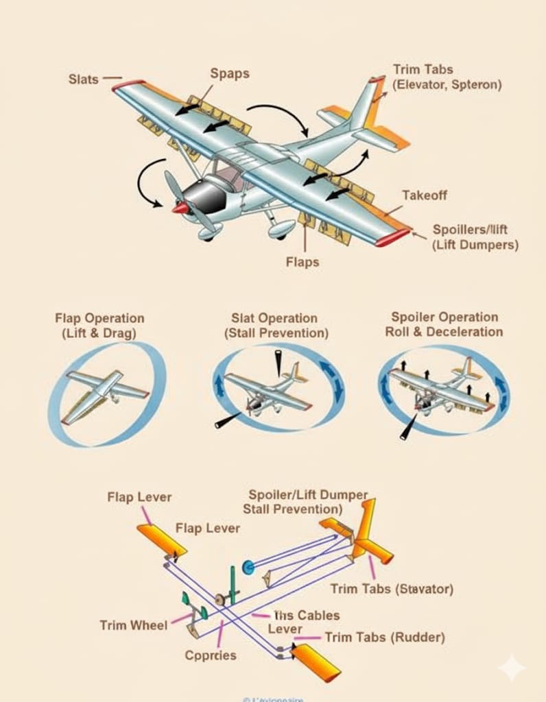
SECONDARY CONTROL SURFACES :
BRIEF ABOUT PITOT TUBE AND RADIO ALTIMETER :
Pitot Tube: A sensor that measures airspeed by comparing incoming ram air pressure with static air pressure.
Radio Altimeter: A device that measures an aircraft's exact height above the ground by bouncing radio waves off the terrain.

TASK 2 UNDERSTANDING AND DESIGNING AN AIR FOIL:
Objective :
- Understand the fundamentals of an Aerofoil, terms associated with it, the nomenclature, concept of turbulence.
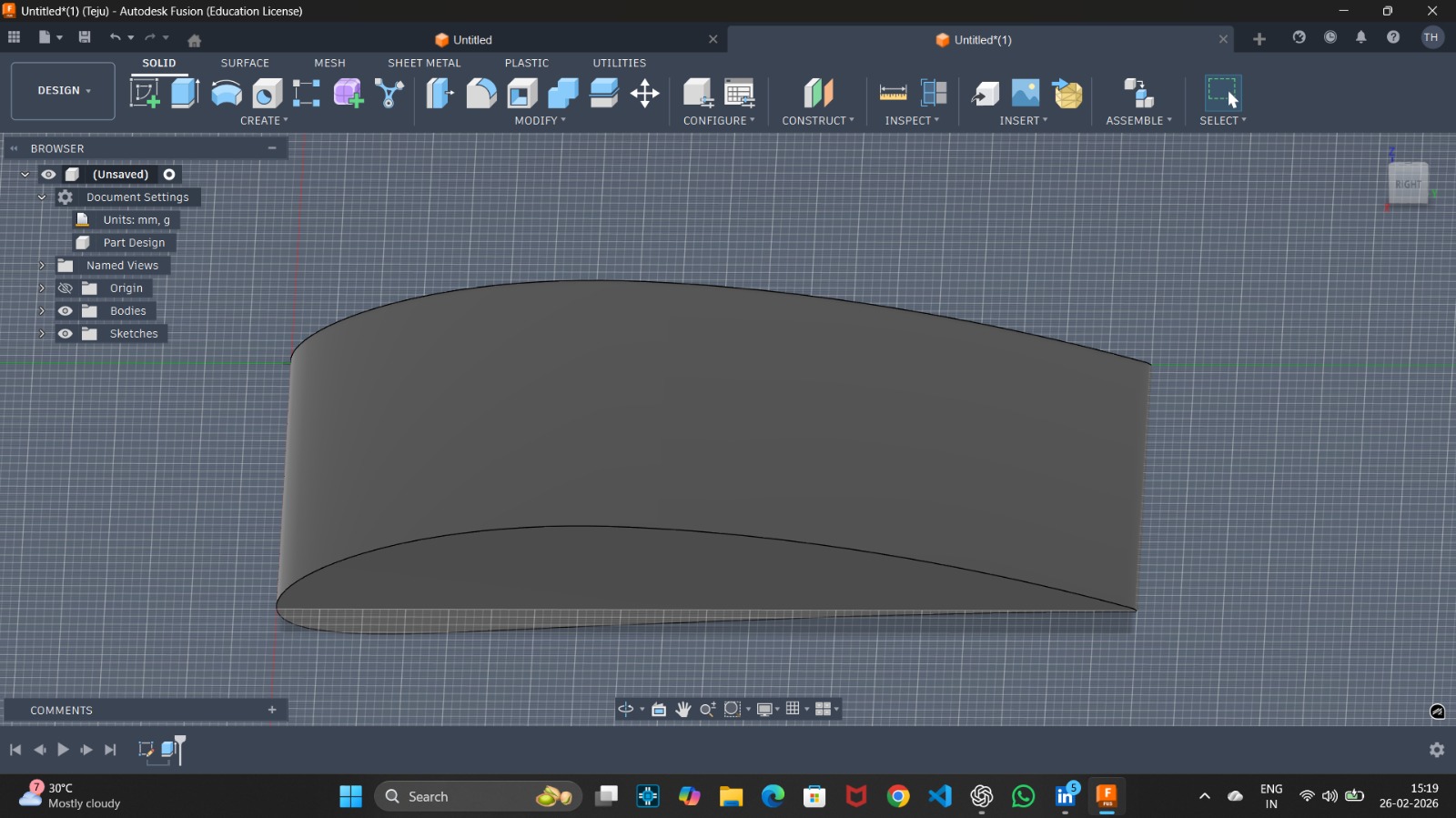
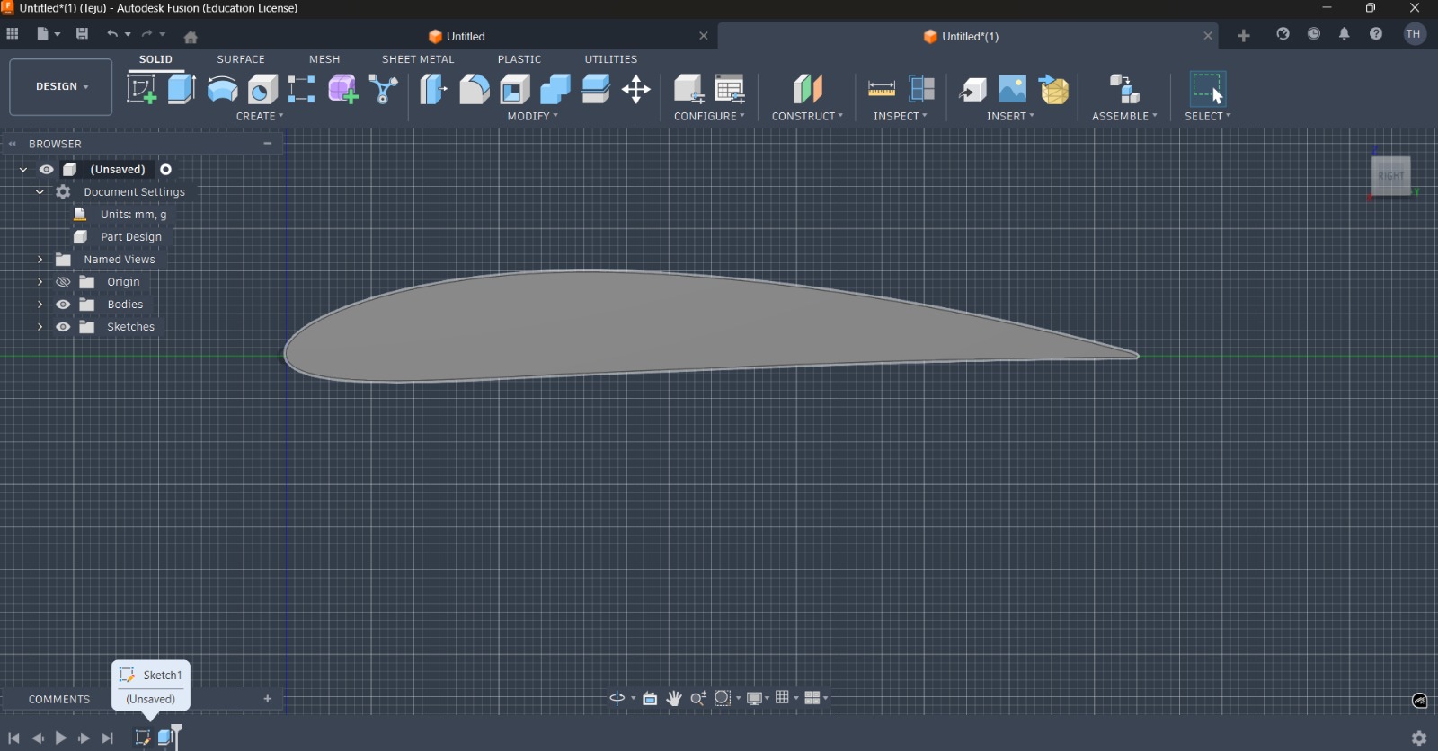
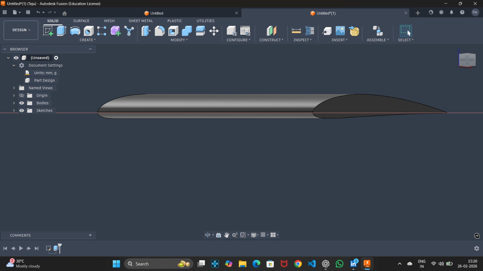
- Use Fusion 360 to model an NACA 4412 air foil of 100 mm chord length & 160 mm air foil span, in Fusion 360 using DAT to Spline/Canvas tool.
- Simulate lift and drag at 25 m/s wind speed to ensure at least 5N lift, use Autodesk CFD for simulation. (Compare with 2 materials, composite based air-foil & wood based air-foil), also state the Angle of Attack in your report.
Learnings and Outcomes:
Basic Aviation terminology:
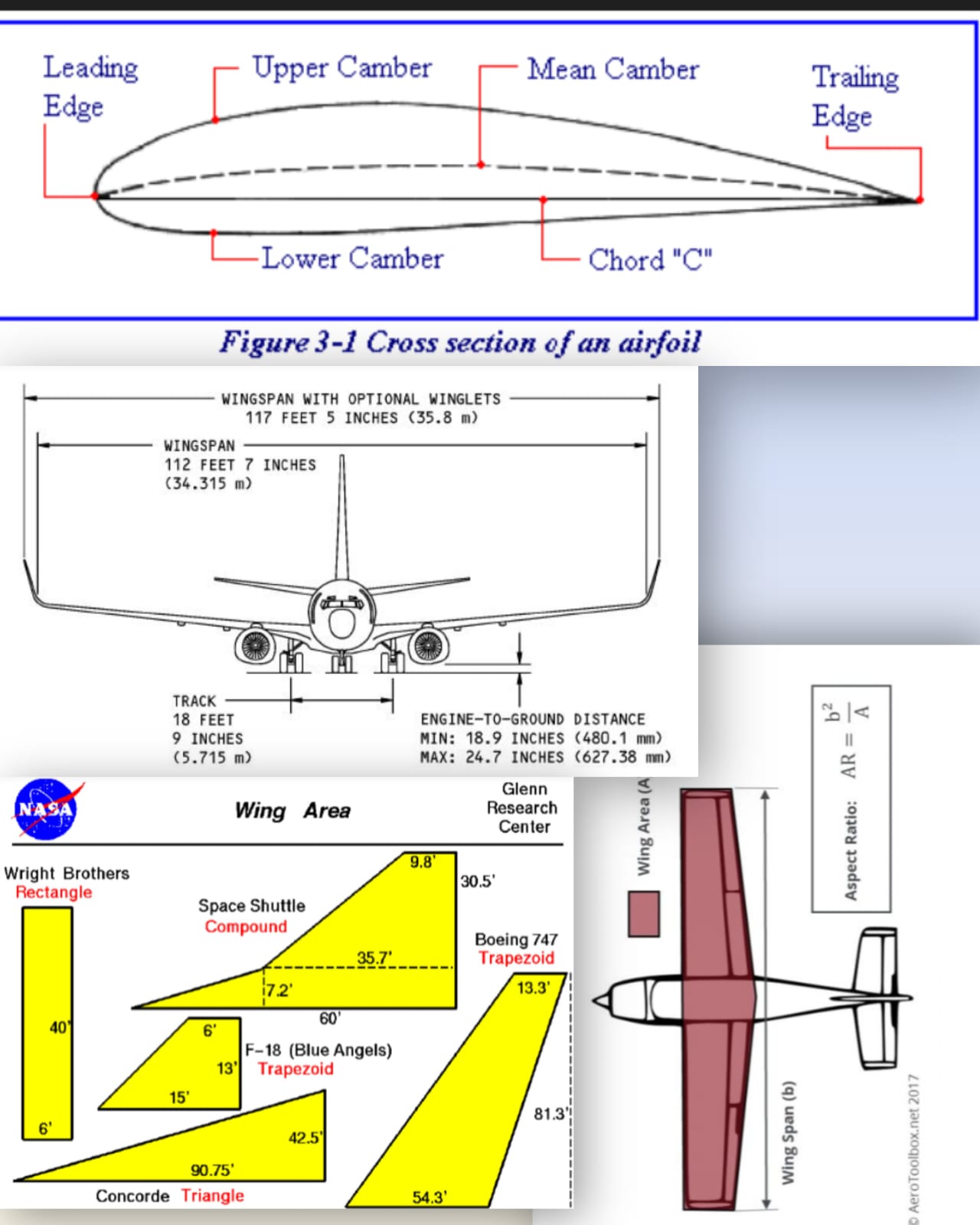
- Airfoil: Any structure designed to produce lift; while wings are the most common example, propellers are also considered airfoils, generating thrust (forward lift).
- Leading Edge: The very front part of an airfoil.
- Trailing Edge: The rear end of an airfoil.
- Chord Line: An imaginary straight line connecting the leading edge to the trailing edge of an airfoil.
- Camber: The curvature of an airfoil, consisting of the Upper Camber (top surface), Lower Camber (bottom surface), and Mean Camber (the average of the two).
- Wingspan: The total distance from one wingtip to the other.
- Wing Area: Calculated by multiplying the average length by the average width of the wing.
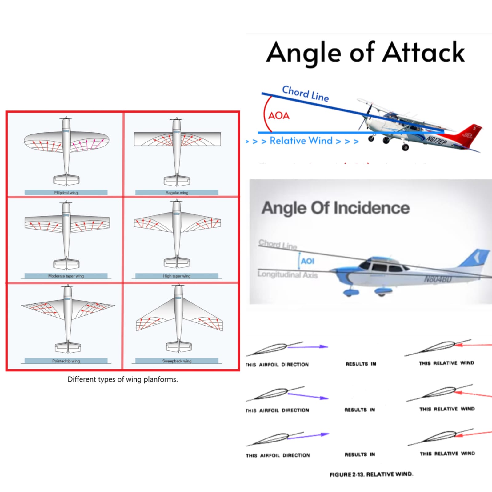
- Planform: The shape of the wing as viewed from above.
- Aspect Ratio: The ratio of the wingspan to the wing chord; gliders utilize high aspect ratios for reduced drag, while fighter jets use low aspect ratios for high maneuverability.
- Angle of Incidence: The angle between the chord line and the longitudinal axis of the aircraft, typically fixed for optimal takeoff speed.
- Relative Airflow: The airflow with respect to the wings, opposing the aircraft's true motion.
- Angle of Attack: The angle between the chord line and the relative airflow, determining many operational limits.
here are the images of each and every technology to understant the terminologies visually.
Airfoil Nomenclature:
For 4 digit
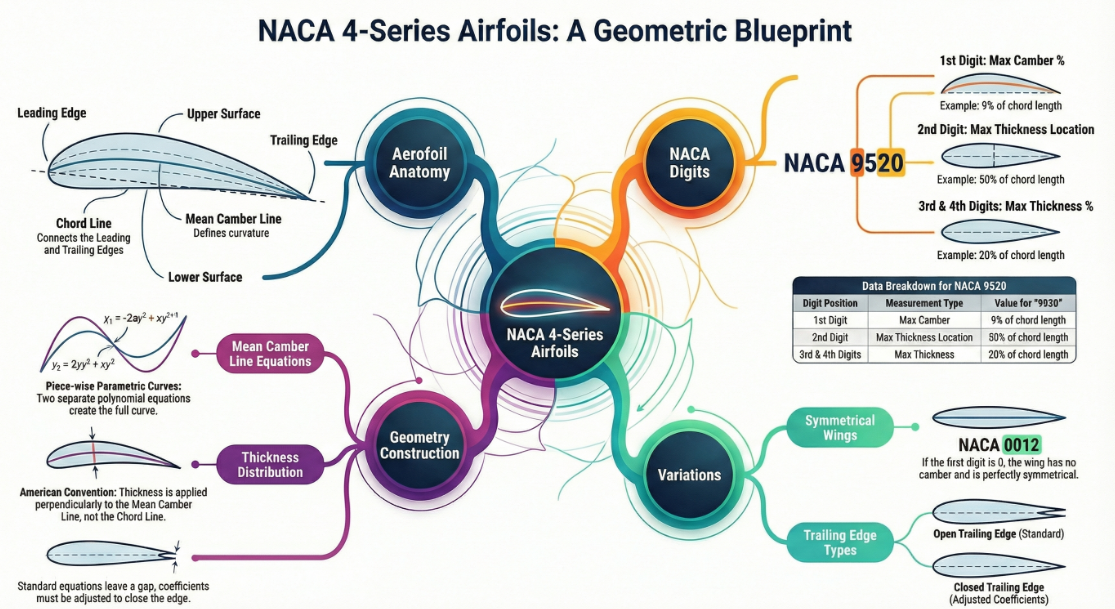
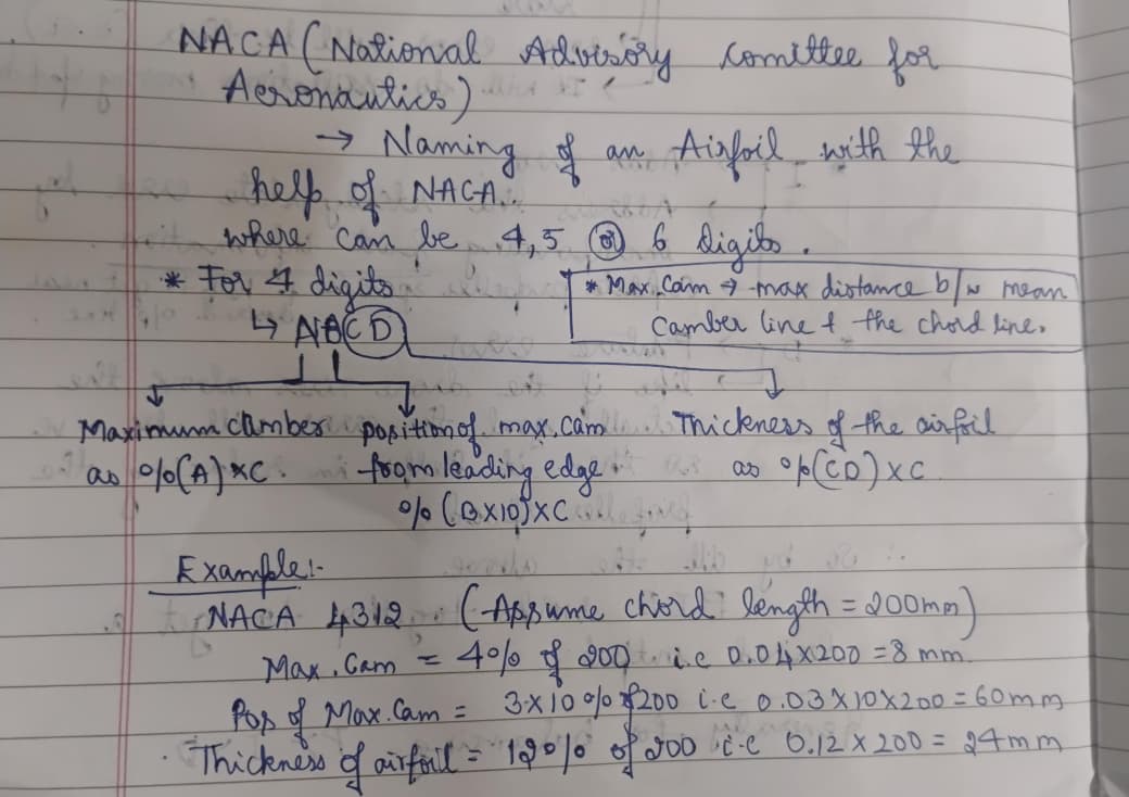
below you can watch the mindmap and understand how nomenclature is done for 4, 5 & 6 digits
click here
Turbulence:
Turbulence occurs when airflow separates from a surface, forming a low-pressure wake with swirling vortices behind the object.
AIRFOIL DESIGN :
CFD CALCULATION
For other Level 1 tasks Click Here