
COURSE
D-P-001
3 Levels · 6 Months.
Introduction to Design & Prototyping.
Jump to:
Level 1
Generic Tasks
Task 1: Print It Yourself
Design a Simple Part and 3D Print It
First learn how a 3D printer works. Then design your own simple parts, a cube and a cylinder, in Onshape. It runs in your browser, so there is nothing to install. No CAD experience needed, so students from any branch can do it. After that, slice your design and print it.
Objective: Understand the full process of 3D printing: design, STL file generation, slicing, and printing.
What to do
- Watch the intro video on 3D printers and read the PLA settings guide.
- Go through the 3D printer SOPs.
- Make an Onshape account with your college email.
- Read the Onshape resource article. Design a cube (30 mm sides) and a cylinder (30 mm diameter, 30 mm height) as two separate parts.
- Export them as an STL file in millimeters.
- Slice the STL in Bambu Studio. Note down the bed temperature and infill density.
- Print it with a coordinator present.
Learning Resources
- Introduction to 3D Printer — How a 3D printer works.
- PLA Printing Guide — Bed temperature, infill, and other PLA settings.
- Types of 3D Printing — FDM vs SLA vs SLS.
- Designing a Simple Part in Onshape for 3D Printing — Refer to the Resource Article.
Suggested Focus
Read the Onshape article first, then start designing. Type mm after every number. Keep the cube and cylinder as separate parts. Check that the STL is in millimeters before slicing.
Note: 3D printing must be done only under coordinator supervision.
Task 2: Dynamic Portfolio & Admin Dashboard
Task Description
Design and develop a dynamic personal portfolio website along with an administrative dashboard that allows the portfolio owner to manage website content through a graphical interface without modifying the source code.
The application should consist of two integrated interfaces:
- Public Portfolio Website: Showcases the student's profile, skills, projects, and achievements.
- Admin Dashboard: Allows the owner to manage and update portfolio content dynamically.
Requirements
1. Public Portfolio
- Develop a responsive website displaying the student's profile, skills, projects, and achievements.
- Retrieve and display portfolio content dynamically through an API.
- Ensure that changes made through the admin dashboard are reflected on the public portfolio.
2. Admin Dashboard
- Create a user-friendly administrative interface for managing portfolio content.
- Implement functionality to add, view, update, and delete projects and skills using forms and controls.
- Ensure that content management does not require direct modification of the source code.
3. REST API Development
- Develop and integrate a RESTful API to facilitate communication between the admin dashboard, backend, and public portfolio.
- Implement appropriate API endpoints and HTTP methods (GET, POST, PUT/PATCH, DELETE) for portfolio content.
- Exchange data using JSON and implement basic input validation and error handling.
4. Data Management
- Store and manage portfolio content using an appropriate in-memory data structure, JSON file, or another beginner-friendly mechanism.
- Ensure that both the public portfolio and admin dashboard access the same application data.
- Database integration is optional.
5. Deployment and Documentation
- Deploy the application using suitable hosting platforms (e.g., Vercel, Netlify, Render, GitHub Pages).
- Maintain the source code in a GitHub repository.
- Document the application architecture, API endpoints, setup instructions, and known limitations in a
README.mdfile.
Expected Outcomes
- Understand the development of dynamic and responsive web applications.
- Learn the fundamentals of REST APIs, HTTP methods, and JSON.
- Understand CRUD operations and client-server communication.
- Gain experience integrating frontend interfaces with an API.
- Develop skills in application deployment, documentation, and error handling.
Suggested Technologies
HTML, CSS, JavaScript, and any suitable backend framework of your choice (Node.js/Express, Python/Flask/FastAPI, etc.).
Submission Requirements
- Public portfolio website URL
- Admin dashboard URL or route
- GitHub repository link
README.mddocumentation- Screenshots demonstrating content management and dynamic updates
Resources
- MDN — Getting Started with Web Development
- Postman Quick Start Guide
- MDN — Making Network Requests with JavaScript
Task 3: Working with GitHub
Familiarize yourself with real-world Git and GitHub workflows including Issues, Branching, Resolving Merge Conflicts, Pull Requests, and GitHub Actions (CI/CD).
Given below is the task repository. Follow the instructions in its README.md to generate your username-specific assignment, document the bugs you find in a GitHub Issue, fix them on a new branch, resolve the practice merge conflict, and open a Pull Request.
What to include in your task report:
- The output of
python my_task.pyshowing your assigned functions. - A link to the GitHub Issue you opened and a brief explanation of the bugs you fixed.
- A link to your Pull Request showing the passing GitHub Actions check.
- Note: PRs are verified by CI and left open for review — they do not need to be merged.
Repository Link: https://github.com/UVCE-Marvel/git-task
Task 4: Hack the Hardware — Ubuntu Command Line & Systems Architecture
Objective
Ubuntu Command Line: Systems Computing, Architecture & Linux
Core Intention
To move beyond rote command memorization and cultivate a deep, foundational understanding of computing systems, the Linux operating system, and system-level problem-solving. Students learn how and why their terminal commands navigate the software stack — from high-level shell calls down to execution units in hardware.
1. Hardware Foundation & Architecture: "The 'U' in CPU"
Topics & Concepts
- The Anatomy of the CPU: The Control Unit (CU), Arithmetic Logic Unit (ALU), internal registers (A, D, Program Counter PC), and bus connections.
- The Fetch-Decode-Execute Cycle: How machine instructions are fetched from memory, decoded by control logic, executed inside the ALU, and written back to registers/RAM.
- Hardware Abstraction: How shell instructions translate through compiler/assembler pipelines into binary micro-operations that flip physical logic gates.
Why You Need This
Understanding hardware abstraction stops you from treating the terminal as a black box. Knowing how registers, memory addresses, and execution cycles work allows you to diagnose performance bottlenecks, manage low-level system resources, write efficient code, and program embedded microcontrollers or microprocessors effectively.
How to Study This Topic
- Nand2Tetris Unit 4 (Machine Language): Write assembly programs for the Hack computer (
Mult.asmandFill.asm) to manually track register states (A, D, M), instruction decoding, and memory-mapped I/O (Screen and Keyboard). - Trace Hardware Metrics via Terminal: Use terminal utilities like
lscpu,lsscsi, andcat /proc/cpuinfoto map abstract CPU concepts (cores, threads, cache sizes, architecture flags) to physical host hardware.
2. Operating Systems, Kernels, and Linux Distributions
Topics & Concepts
- The Operating System's Core Role: Memory virtualization, process scheduling, storage management, and hardware safety.
- What is a Kernel? The privileged (Ring 0) bridge between user space applications and physical hardware via System Calls (syscalls).
- Linux Distributions vs. The Kernel: Distinguishing between the upstream Linux kernel and distributions (Ubuntu, Debian, Fedora, Arch) that package userland tools, package managers, and display servers.
Why You Need This
When an application or script crashes, hangs, or fails to start, the issue usually lies in kernel-level resource access, missing dependencies, or system call errors. Understanding OS mechanics enables you to debug real-world server, embedded Linux, and edge-computing environments.
How to Study This Topic
- System Call Observation: Run simple terminal commands through
strace(e.g.,strace ls) to observe how userland utilities request kernel services (e.g.,openat,read,write). - Virtual Filesystem Exploration: Navigate
/procand/systo understand how the Linux kernel exposes running system states directly as text files.
3. The Linux Environment & Core System Concepts
Topics & Concepts
- Terminal vs. Shell: Distinguishing between terminal emulators (user interface) and shells (
bash,zsh— command interpreters). - Filesystem Hierarchy Standard (FHS): Root (
/), user space (~), device files (/dev), configuration files (/etc), and system binaries (/bin,/usr/bin). - Permissions & Security Model: Read, write, execute (
rwx) flags, file ownership (user:group), and privilege escalation (sudo). - Processes & Signals: Process IDs (PIDs), job control (
&,fg,bg), environment variables, standard streams (stdin,stdout,stderr), and piping (|).
Why You Need This
The command line is the primary interface for remote servers, cloud infrastructure, robotics platforms (like ROS 2), and build environments. Mastering streams, permissions, and process controls lets you automate complex workflows and manage systems without relying on a graphical user interface.
How to Study This Topic
- Interactive Terminal Scenarios: Solve practical system issues (e.g., permission-denied errors, locating run-away processes with
toporps aux, killing stuck tasks via signals). - Pipe Construction: Practice stringing fundamental tools (
grep,awk,sed,cut,sort) together to parse logs and extract target metrics.
4. Practical Tips for Terminal Execution
- Read the Manual (
man): Never guess command flags. Runman(or usetldr) to inspect flags and syntax. - Inspect Exit Codes: Check
$?immediately after running a command to see if it succeeded (0) or threw an error (non-zero). - Fail Fast & Safely: Use
lsorechoto verify wildcard patterns (e.g.,echo *.log) before executing destructive commands likerm *.log. - Understand Standard Streams: Treat
stdout(1) andstderr(2) separately so you don't miss error messages when redirecting logs. - Leverage Autocompletion & History: Use Tab key completion to avoid typos and Ctrl + R to search previous command history quickly.
5. Hands-on Problem Statement: System Audit & Log Processing Pipeline
You are tasked with inspecting a remote Linux workstation that has experienced intermittent slowdowns. Without using any Graphical User Interface (GUI), complete the following steps using terminal utilities:
- Hardware & Kernel Inspection:
- Identify the total number of physical CPU cores, architecture model, and the running Linux kernel version. Output these values into a file named
system_summary.txt.
- Identify the total number of physical CPU cores, architecture model, and the running Linux kernel version. Output these values into a file named
- Process & Resource Triage:
- Locate all running processes consuming memory on the system. Filter out system daemons to find the process ID (PID) of the process running under your user space, and write the output to
process_audit.log.
- Locate all running processes consuming memory on the system. Filter out system daemons to find the process ID (PID) of the process running under your user space, and write the output to
- Permission & File System Reorganization:
- Create a secure directory structure under
~/workspace/audit_logs/. - Change the directory permissions so that only your user has read, write, and execute permissions (
700). Move all generated log files into this directory.
- Create a secure directory structure under
- Log Data Parsing & Filtering:
- Given a system log file containing mixed informational and error entries, write a single-line command pipeline using
cat,grep,awk, andsortto extract only unique[ERROR]messages and count their occurrences.
- Given a system log file containing mixed informational and error entries, write a single-line command pipeline using
6. What You Must Build
To successfully complete this task, you must build and deliver:
- Draw Your Own Architecture:
- Draw how you think the CPU used to look before going through it and how it looks now according to you. Wrong answers welcomed — we want to see your conceptual understanding.
- Custom Automated Shell Script (
system_health.sh):- A bash script that gathers system uptime, CPU core count, active memory usage from
/proc/meminfo, and active user processes, formatting them into a readable text report.
- A bash script that gathers system uptime, CPU core count, active memory usage from
- Execution & Analysis Log Notebook:
- A written document explaining:
- The step-by-step resolution of the Problem Statement.
- Annotations of key
straceoutputs showing at least two system calls (openat,write). - Explanations for why specific piping choices (
|) were used during log extraction.
- A written document explaining:
7. Foundational Command-Line Exercises
- Navigation & Inspection:
pwd,cd,ls -la,tree - File & Directory Operations:
touch,mkdir -p,cp -r,mv,rm -rf - Content Viewing & Inspection:
cat,less,head,tail -f,echo,grep
8. Resource Links
Computer Architecture & Nand2Tetris
- Nand2Tetris Official Course & Software Suite — Hands-on building of a computer system from basic NAND logic gates up to an Operating System.
- Nand2Tetris Unit 4 (Machine Language) — Covers Hack assembly programming, register operations (A, D, M), pointer manipulation, and memory-mapped I/O.
- Nand2Tetris Chapter 5 (Computer Architecture) — Focuses on building the Hack CPU, instruction decoding logic, and memory integration.
Linux & Command Line Fundamentals
- The Linux Command Line by William Shotts (Free PDF) — Comprehensive reference covering basic shell operations, environment management, and shell scripting.
- Linux Journey — Interactive, modular guide breaking down Linux command line operations, text manipulation, permissions, process handling, and kernel mechanics.
- LinuxCommand.org Tutorials — Structured, step-by-step tutorials on command execution, storage navigation, and terminal problem-solving.
- TLDR Pages — Community-driven, simplified man pages focusing on practical, real-world command usage examples.
Task 5: Operation Blackout — Decode the Hidden Message
An unknown source has transmitted a mysterious sequence of numbers, and your mission is to uncover the secret hidden within it. The data may appear random, but with the right transformations, a meaningful pattern will emerge.
Using NumPy, investigate the encoded array, reshape it into a square matrix, experiment with transposing and reversing its elements, and visualize the result using Matplotlib. Follow the cryptic clues, piece together the original arrangement, and reveal the hidden message!
Can you crack the code and complete Operation Blackout?
- Download the NumPy Array: https://drive.google.com/file/d/1lbzxfFuLJSNRXZqT63z8teFWCT44xfRk/view?usp=drivesdk
Learning Resources
NumPy
- NumPy Quickstart — Official Documentation — Array shapes, indexing, slicing, and transformations.
- Indexing on ndarrays — NumPy — Array indexing and slicing.
- NumPy Tutorial — W3Schools — Beginner-friendly reference.
- NumPy Tutorial — DataCamp — Tutorial covering common NumPy operations.
Matplotlib
- Matplotlib Tutorials — Official Documentation — Plotting fundamentals and customization.
- imshow() — Matplotlib Documentation — Display a 2D array as an image.
- Colormap Guide — Matplotlib — Choose a colormap for visualizing the matrix.
- Matplotlib Tutorial — DataCamp — Introduction to plotting with Matplotlib.
YouTube Videos
- NumPy Tutorial for Beginners — Keith Galli — Arrays, slicing, reshaping, and other NumPy basics.
- NumPy Tutorial — Corey Schafer — A comprehensive explanation of NumPy fundamentals.
- Matplotlib Tutorial — freeCodeCamp — Creating and customizing plots.
- Introduction to Numerical Computing with NumPy — Enthought — Search link for a practical NumPy workshop.
Suggested Focus
Before solving the puzzle, review array size and shape, reshape(), transpose(), slicing, and reversing with negative-step slices. Then review imshow() and colormaps. Check that the number of array elements matches the target matrix dimensions before reshaping.
Note: The resources are supplementary learning materials. Students should understand and explain the transformations and matrix operations used in their own solutions.
Task 6: Build Your Own Brain — Linear Regression from Scratch
In this task, you will implement a Linear Regression model from scratch using NumPy to develop a deeper understanding of the underlying principles of machine learning. Using the California Housing dataset, you will train your model using Gradient Descent, investigate the effects of learning rate and feature scaling, and visualize the model’s learning process.
You will then compare your implementation with sklearn.linear_model.LinearRegression using standard evaluation metrics, including MSE, MAE, and R². Through this comparative analysis, you will gain practical insights into model optimization, performance evaluation, and the advantages of established machine learning libraries.
Objective: Develop a fundamental understanding of Linear Regression by implementing, evaluating, and comparing a custom model against a standard library implementation.
Learning Resources
Concepts and Implementation
- Google Machine Learning Crash Course: Linear Regression — Introduction to linear regression, features, predictions, and loss.
- Google Machine Learning Crash Course: Gradient Descent — How gradient descent updates model parameters.
- California Housing Dataset — scikit-learn — Dataset description and loading information.
- StandardScaler — scikit-learn — Feature standardization.
- LinearRegression — scikit-learn — Reference for the library implementation.
- Regression Metrics — scikit-learn — Evaluation metrics and model assessment.
- Coding Linear Regression from Scratch — Towards Data Science — Supplementary implementation walkthrough.
- Linear Regression from Scratch — AskPython — Step-by-step coding reference.
YouTube Videos
- Linear Regression, Clearly Explained — StatQuest — Understand the intuition behind fitting a line and R².
- Gradient Descent, Step-by-Step — StatQuest — Visual explanation of gradient descent and parameter updates.
- Linear Regression from Scratch with NumPy — MLTut — Code a basic regression model with NumPy, MSE, and gradient descent.
- Building the Gradient Descent Algorithm — Nicholas Renotte — Practical coding walkthrough.
Suggested Focus
Start with the linear regression and gradient descent videos before coding. Then implement the model using NumPy, standardize features using training data only, and compare both models on the same held-out test set. Plot the loss over iterations and compare MSE, MAE, and R².
Task 7: Resource Article Writing using Markdown
Markdown is an easy-to-use markup language that is used with plain text to add formatting elements (headings, bulleted lists, URLs, code blocks) without the use of a formal text editor or HTML tags. Markdown is device-agnostic and displays formatting consistently across all device types.
Write a technical resource article on a topic of your choice and publish it on the MARVEL website. Refer to the linked article for formatting guidelines and instructions.
Resource Link: https://hub.uvcemarvel.in/article/52f92f36-fb8a-45da-8f28-686bf4efefff
Task 8: Arduino vs ESP32 — Sensor-Based DC Motor Control
Note: Before working on this task, it is mandatory to have completed basic reading on Arduino Uno and ESP32. Do not proceed to hardware wiring without reviewing the prerequisites.
Problem Statement
Build a DC motor control system using Arduino UNO R3 and ESP32 to compare their pin configurations, analog inputs, PWM control, and voltage levels. Use an HC-SR04 ultrasonic sensor to measure distance and a potentiometer to control motor speed through a suitable motor driver. The motor must stop when an object comes closer than a predefined distance of 15 cm.
Implement the same basic setup on both boards, ensuring that all sensor signals are compatible with the selected board. Finally, extend the ESP32 setup with a web page that allows users to control motor speed using a slider and stop the motor using a button. Identify what additional hardware the Arduino UNO would need to support similar Wi-Fi control.
Simulation Tips (Simulate before hardware wiring):
- For Arduino Uno: Use Tinkercad Circuits, a beginner-friendly web-based simulator.
- For ESP32: Use Wokwi, a web-based simulator with full ESP32 and Wi-Fi emulation.
Why You’ll Need This
Arduino UNO and ESP32 can perform similar tasks, but their pin configurations, operating voltages (5V vs 3.3V), analog-to-digital converters (ADC), PWM capabilities, and wireless features differ. A circuit that works on one board may damage or fail to work safely on the other.
Through this task, you will explore these differences by building and testing the same application on both boards. You will also learn why a sensor powered by 5V may require voltage level shifting (e.g., a voltage divider) before its output can be safely connected to an ESP32's 3.3V GPIO, and how PWM is implemented on each platform.
What You Must Build
- Sensor and Motor Control: Connect the HC-SR04, potentiometer, and DC motor through a suitable motor driver (e.g., L293D or L298N). Use the potentiometer to vary motor speed and display distance readings on the Serial Monitor. The motor must stop when an object is detected within 15 cm.
- Implement on Both Boards: Build and test the system using both Arduino UNO R3 and ESP32. Identify the required pins and adapt the wiring and code for each board.
- Check Voltage Compatibility: Determine the voltage requirements of each component. Use a voltage divider for the HC-SR04 Echo signal when connecting it to the ESP32, and ensure the potentiometer output stays within the board's permitted input voltage (3.3V max for ESP32).
- Add Web-Based Control: Extend the ESP32 program with an asynchronous web server hosting a web page with a speed slider (0% to 100%) and a Stop button. The web interface controls motor speed, while the distance-based stop condition overrides the selected speed for safety.
- Compare the Boards: Document the differences you observed in pin usage, analog readings, PWM implementation, voltage compatibility, and Wi-Fi setup. Explain what additional hardware would be required to provide similar web-based control using Arduino UNO R3.
Learn Before You Build
Web Server Tutorials for ESP32:
Task 9: The "Joint" Venture — Soldering
What You Are Required to Do
- Soldering Station Tour: Go around the soldering station, inspect all the equipment, and identify what they are (soldering iron, brass sponge, flux, solder wick, helping hands, fume extractor).
- Coordinator Briefing: Gather your domain batchmates and get a one-time safety and technique briefing from any of your domain coordinators.
- Perfboard Circuit Assembly: Solder a simple circuit (LED Fader Circuit) on a perfboard. This must be completed individually.
- Interactive Reference: Tinkercad LED Fade Circuit
- Components Required:
- 1x 100 µF electrolytic capacitor
- 1x 1 kΩ resistor
- 1x 10 kΩ resistor
- 1x PN junction diode (1N4007 or similar)
- 1x LED of your choice
- 1x Pushbutton switch
- Power supply (5V – 9V)
- Assembly Guidelines:
- Wiring must be done using single-stranded wire.
- Tin the wire ends and soldering iron tip prior to soldering to ensure strong, clean solder joints.
- Verify circuit continuity before applying power.
- Optional Credit: Probe the fading waveform using an oscilloscope to observe the capacitor discharge curve.
- Theoretical Knowledge: Study the composition of solder wire (e.g., 60/40 leaded vs lead-free SAC305), types of flux (rosin, no-clean, water-soluble), and their roles in preventing oxidation.
- Board Types: Learn the differences and applications of Breadboards, Perfboards / Zero-PCBs, Stripboards, and custom etched PCBs:
- Hazards and Safety Measures: Review safety protocols regarding burns, toxic fumes, ventilation, and eye protection:
Task 10: VRPS & Oscilloscope Fundamentals
Coming soon.
Task 11: 555 Astable Multivibrator with 60% Duty Cycle
Objective
Design, build, and measure a 555 astable multivibrator. By the end you should be able to:
- Choose timing resistors (R1, R2) and capacitor (C) for a target frequency and duty cycle.
- Wire the NE555 timer IC as an astable oscillator on a breadboard.
- Measure frequency, period, high time (t_high), low time (t_low), and duty cycle on a Digital Storage Oscilloscope (DSO).
- Explain any discrepancies between theoretical designed values and actual measured values.
The Task
Design a 555 astable multivibrator whose output has a 60% duty cycle, build it on a breadboard, and observe the output waveform on a DSO.
- Target Frequency: Pick 1 kHz so the waveform is clear and easy to analyze on the scope.
Steps
- Read First: Go through the resources below until you can write the astable formulas for frequency and duty cycle in terms of R1, R2, and C, and explain what charges and discharges the capacitor in each half of the cycle.
- Design on Paper: From the target frequency (1 kHz) and 60% duty cycle, derive the ratio of R1 to R2, choose a standard capacitor value C, and compute R1 and R2. Show all calculation steps.
- Pick Real Parts: Round your calculated resistor values to standard component values available in the lab and recompute the exact theoretical frequency and duty cycle.
- Build: Wire the NE555 on a breadboard with a 5V to 12V DC supply, your components R1, R2, C, and a 10 nF decoupling capacitor from Pin 5 (Control Voltage) to Ground. Check the datasheet pinout before powering on.
- Probe: Connect the DSO probe to Pin 3 (Output) and Ground. Adjust the timebase so that 2 to 3 full waveform cycles are visible, and verify that probe attenuation (1x/10x) matches the scope channel settings.
- Measure: Record the period, frequency, high time (t_high), and low time (t_low), and compute the measured duty cycle using the DSO's cursor or automatic measurement tools.
- Compare: Tabulate designed vs. calculated-with-real-parts vs. measured values, and explain any differences (component tolerances, internal transistor drops, parasitic breadboard capacitance).
Deliverables
- Design Sheet: Calculations showing the derived R1/R2 ratio, chosen capacitor value, calculated resistor values, and recalculated metrics for real parts.
- Circuit Schematic: Labeled diagram with pin numbers and component values.
- Breadboard Photo: High-resolution image of the wired circuit with DSO probe connected.
- DSO Screenshot/Photo: Waveform showing at least 2 full periods with measured frequency and duty cycle parameters visible.
- Comparison Table: Designed vs. calculated (real parts) vs. measured values for frequency and duty cycle.
- Short Analysis (3–4 sentences): Why can a standard 2-resistor 555 astable circuit never achieve a duty cycle below 50%, and why is 60% achievable without adding an external bypass diode?
Resources
- 555 Timer Math — Derivation & Equations
- Astable Multivibrator using IC 555 — IIT Kharagpur Virtual Lab
- NE555 Datasheet (Texas Instruments)
- Ben Eater — How a 555 Timer Works in Astable Mode (YouTube)
- 555 Astable Working & Derivations (YouTube)
- Measuring Frequency, Duty Cycle, & Pulse Width on an Oscilloscope (YouTube)
Task 12: Prime Number Detector with a K-Map
Objective
Learn Karnaugh maps from scratch by using one to design a real circuit. By the end you should be able to:
- Fill a K-map from a truth table.
- Circle valid groups (sizes 1, 2, 4, 8) and read an equation off them.
- Explain why grouping works: two cells that touch differ in exactly one input, so that input drops out.
- Build the result in logic gates and check it against every input combination.
The Task
Design and build a circuit with four inputs D C B A (a 4-bit number from 0 to 15, A is the least significant bit, D is the most significant bit). The output LED turns on when the number is prime. Treat 0 and 1 as not prime.
Do this in Tinkercad Circuits using four slide switches as inputs, one LED as output, and plain gates (AND, OR, NOT) in between. No decoder or other "smart" ICs.
Steps
- Read first: Go through the K-map resources below until you can answer: what does it mean for two cells to "touch", and what are the legal group sizes?
- Truth table: Write all 16 rows and mark the output for each.
- Raw circuit: Write one AND term for every row where the output is 1, OR them together, and build it in Tinkercad. Count the gates. This is your baseline.
- K-map: Fill in the blank map below from your truth table (cell numbers are the decimal value of D C B A).
- Group: Circle groups of 1s. Use the largest groups you can, let groups overlap, and remember that the edges of the map wrap around (left touches right, top touches bottom).
- Equation: Write one product term per group and OR them.
- Simplified circuit: Build it in Tinkercad and count the gates.
- Verify: Run through all 16 switch combinations and confirm both circuits match your truth table. Write down your predicted output for 3 inputs before testing them.
Blank K-map (rows D C, columns B A)
+----------+----+----+----+----+
| D C \ BA | 00 | 01 | 11 | 10 |
+----------+----+----+----+----+
|    00    |  0 |  1 |  3 |  2 |
|    01    |  4 |  5 |  7 |  6 |
|    11    | 12 | 13 | 15 | 14 |
|    10    |  8 |  9 | 11 | 10 |
+----------+----+----+----+----+
| D C \ B A | 00 | 01 | 11 | 10 |
|---|---|---|---|---|
| 00 | 0 | 1 | 3 | 2 |
| 01 | 4 | 5 | 7 | 6 |
| 11 | 12 | 13 | 15 | 14 |
| 10 | 8 | 9 | 11 | 10 |
Axis order is 00, 01, 11, 10 on purpose, so that neighbouring cells always differ in only one input. Use it as given.
Deliverables
- Tinkercad share link (viewable by anyone with the link) containing both the raw and the simplified circuit, labeled.
- One sheet (photo or scan is fine) with the truth table, the filled K-map with groups circled, and your final equation.
- Prediction table: 3 inputs, your predicted output, and the actual output.
- Gate counts: raw circuit vs. simplified circuit.
- Short answer (3 to 4 sentences): why can two touching cells be merged into one term?
Resources
- Karnaugh map playlist (YouTube) — The main K-map course. Cover the introduction and the 4-variable videos (grouping and wrap-around) before starting the task.
- Karnaugh Maps with 4 Variables (YouTube) — A second explanation of the same material, useful if the playlist doesn’t click.
- Logic Gates in Tinkercad (YouTube) — Placing gates, switches and LEDs and running the simulation.
- Digital Electronics: Logic Gates Circuits on Tinkercad (YouTube) — More Tinkercad gate builds if you get stuck wiring.
- Karnaugh Mapping worksheet (All About Circuits) — Practice questions to try before you start the task.
- Tinkercad Circuits
Task 13: Active Participation
- Technical Events: Participate in any technical event, hackathon, paper presentation, or competition (inter-college or intra-college) and submit the certificate of participation or achievement.
- MOOC Completion: Enroll in and successfully complete an approved Massive Open Online Course (MOOC) on platforms like NPTEL, Coursera, edX, or Swayam.
Task 14: Datasheets Report Writing
Study the official technical datasheet of any one of the following components and write a comprehensive analysis report:
- MQ-135 Gas Sensor IC:
- Operating principles and target gas sensitivities ($NH_3$, $NO_x$, alcohol, benzene, smoke, $CO_2$).
- Circuit schematic and load resistance ($R_L$) calibration curve.
- Freundlich Adsorption Isotherm / sensitivity characteristics graph.
- L293D Dual H-Bridge Motor Driver:
- Internal block diagram and H-Bridge working mechanism.
- Logic truth table for forward, reverse, and braking states.
- Voltage ratings ($V_{CC1}$ vs $V_{CC2}$), peak current capabilities, internal clamp diode protection, and PWM speed control interfacing.
Task 15: SadServers — "Like LeetCode for Linux"
SadServers is an interactive platform to test your real-world Linux troubleshooting and debugging skills under realistic production scenarios.
Scenario: Complete the "Command Line Murders" investigation challenge. Troubleshoot the environment, parse through the clues using terminal tools, and make the sad servers happy!
Resources & Links
Level 2
LEVEL 1
Electronic Design
1. Engineer’s Swiss Army Knife
Create a Matlab account and complete the MATLAB Onramp course and obtain the certification.
2. Cut, Pass, Repeat
- Objective: To learn about Band Pass Filters
- Task: Design a second order active band pass filter(using OpAmps) that amplifies the signal to roughly 1.5 times the original signal.Cutoff range between 4kHz and 10kHz
- Platform: LTSpice

3. SPICEy Code
- Objective: To learn SPICE code
- Task: Write basic SPICE code for a MOS inverter, AND and OR Gates
- Platform: LTSpice
4. From Low to Woah!
- Objective: Voltage multiplier using capacitor pumps and a 555 Timer IC
- Task: Pump up 9V to 18V at first, then cascade the pump to get 27V.
- Platform: LTSpice/TinkerCAD
5. The Power Shuffle: Buck-Boost Edition
- Objective: To learn about the DC-DC Converters
- Task: Learn about Boost and Buck converters and perform the following:
- Build a 1.5V to 5V DC-DC Boost converter
- Build a 12V to 5V DC-DC Buck converter
- Platform: LTSpice
- Resource
- Task: Learn about Boost and Buck converters and perform the following:
6. 4 Bits to Rule Them All
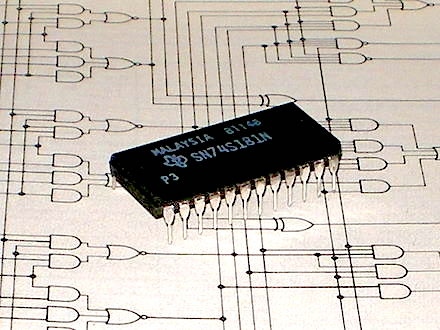
Your task is to design and implement a 4-bit Arithmetic Logic Unit (ALU) in CircuitVerse. The ALU should perform the following operations: addition, subtraction (using 2’s complement), and logical operations (AND, OR, XOR). You must also design a control unit to select the desired operation based on input signals and display the result along with any carry/overflow flags when applicable.
Start by creating a 4-bit adder using basic logic gates, ensuring correct handling of carry bits. Extend this design to support subtraction by using 2’s complement, and then implement the logical functions (AND, OR, XOR) with the same 4-bit inputs. The ALU must be efficient in terms of gate usage and scalable for future expansion. Bonus challenge: Add a feature to invert all bits of a 4-bit input (negation).
Resources:
- Digital Logic Gates
- Full Adder Circuit
- How to Create a 4-Bit Adder
- 2's Complement for Subtraction
- ALU Design and Implementation
- Control Unit Basics
- Building a Basic ALU
7. The PCB Revolution
- Objective: Learn basics of PCB Designing
- Task: Apply for the Altium student license and complete the Altium Student Lab PCB coursework.
- Platform: Altium Designer
Resources:

8. Convolution Countdown
- Objective: To theoretically learn basics of Digital Signal Processing
- Task: Learn basics of DSP including an introduction to signals, systems and mathematical transforms such as Z-Transform and Fourier Transform. Perform a simple Linear Convolution in MATLAB for two 4 sample discrete signals.
- Platform: MATLAB

9. Whose Array Is It Anyway?
- Objective: To understand and implement combinational logic design using PAL and PLA structures
- Tasks:
- Read up on basics of PROM, Programmable Logic Arrays and Programmable Array Logics and understand the key differences
- Basics:
- Design a logic circuit that outputs '1' if the number of 1’s in a 3-bit input (A, B, C) is odd
- In this task you need to first design using a PAL
- Then design the same thing using a PLA
- For both it's mandatory to draw fuse tables of AND Array and OR Array and show the fuse and blown connections.
- Taking it up a notch:
- Design a controller that manages three lights in a smart home system based on these conditions - Motion sensor (M), Light level sensor (L), Time of day (T), Manual override (O) - using either PLA or PAL and justify the design.
- Platform: Logisim Evolution
- Resources:
- Tasks:
10. Your Logic, Preloaded
- Objective: To understand the concept of Look-Up Tables (LUTs)
- Tasks:
- Read up on basics of Look Up Tables in digital electronics
- Implement a 2-input XOR function using a 4x1 LUT (2 input bits select one of 4 pre-stored outputs).
- First, manually create the truth table for XOR.
- Then, program a 4x1 LUT with the correct outputs based on the truth table.
- Simulate how inputs select different stored outputs.
- Platform: CircuitVerse or Logisim Evolution
- Resources:
- Tasks:
Mechanical Design
Introductory Module
Fundamentals of CAD
To successfully complete the other tasks at hand, it is essential that you have a good understanding of the concepts and ideas presented in the provided PDF document. We strongly recommend that you read the document thoroughly and make sure that you have a solid grasp of the information it contains before proceeding with the other tasks. https://drive.google.com/file/d/1_AMMsWewL0sAlRoD_eP7sz8Rmb6gJMfO/view?usp=sharing
Apply for Autodesk Educational licence
https://www.autodesk.com/education/edu-software/overview?sorting=featured&filters=individual
1. Introduction to Engineering Drawing
Isometric & Orthographic Projections
Using a mini drafter, draw at least 4 models as illustrated, and furnish them to the lab.
Thoroughly review the provided PDF and illustrate seven orthographic projections accordingly. https://drive.google.com/file/d/11tY1ARdFKNEoMBMrf_mybfLTuzmxevpZ/view?usp=sharing
Thoroughly review the provided PDF and illustrate seven Isometric projections accordingly. https://drive.google.com/file/d/12XvAr_lD9NC-aNlG5I-07V3eAKhnGGha/view?usp=sharing
2D Drawings in CAD
Generate 2D drawings from the designated folder to visually represent the desired design in the Sketcher workspace.
Folder: https://drive.google.com/drive/folders/1qGEs5cemy2DjgBbmVM0f7n7XfrIndvMs?usp=sharing
Youtube link: https://youtu.be/47_zypTqZe0
2D Drafting
Draw a Level-2 Sierpenski Triangle and generate a drawing sheet with dimensions neatly labelled.
3D Drafting
Task 1
Draw an Allen key and generate a labelled drawing sheet for the same. Along with a 3d model for the same in Fusion 360.
Parameters:
Length - 55mm
Width - 20mm
Size - 3mm
Task 2
With reference to the drawings, 3D draft at least 3 machine parts in Fusion 360.
Folder:https://drive.google.com/drive/folders/1gQuomsJkHP0R7zjmB2OGLx-xAGxk798u?usp=sharing
Study Material
https://help.autodesk.com/view/fusion360/ENU/courses/AP-SKETCH-FUNDAMENTALS
https://help.autodesk.com/view/fusion360/ENU/courses/AP-SOLID-EXTRUDE
https://www.youtube.com/watch?v=VAhYn7pKLWs
https://youtu.be/jmpKpWzhbGQ
2. 3D Modelling
Solid Modelling
Design a simple aerofoil for an HTOL aircraft using Fusion360.Make use of Plug-Ins and add ons to generate a NACA aerofoil. Understand the nomenclature of NACA profile and understand the meaning of those terms. We expect you to understand the basic aspects of a wing design like leading, trailing edge and camber line.
1.Airfoil Introduction
2.NACA Nomenclature
3.Short Tutorial
4.One more tutorial
Surface Modelling:
Understand what is a toroidal propellor and what is it's necessity or use.Take an introductory course or go through a playlist explaining forms feature in Fusion 360. Design a toroidal propellor which is compatible with a 1000kv BLDC Motor available in the lab.
Reference
1.Introduction to Forms
2.What is a Toroidal Propellor?
2.Toroidal Propellor Modelling
Sheet Metal
Design a Postbox for MARVEL using sheet metal environment in Fusion 360.
Thickness - 1mm
Height - 1ft
You will be judged for usability | compatibility | creativity | optimization |
Resource
1.Introduction to the environment
2.Playlist to understand the environment better
Organic Designing using forms
Design a Hollow vase for MARVEL using the Forms feature in Fusion360. Parameters Base Width/Diameter - 70mm Aperture - 55mm Thickness - 2mm Resource 1.Forms introduction
3. Prerequisite for assembly in Fusion 360
Learn about the difference between bodies and components in Fusion360. Resource:
https://youtu.be/46UNmpQdbVc?si=kbC8jYi_Fd4sMaNZ
https://www.youtube.com/watch?v=TzG2deElWqI
4. Assembly and Animation
Design one of the Mechanisms from scratch from the resources given below. Understand the basics of modelling, Assembly and Animation
Resources:
1.Simple Slider Mechanism
2.Quick Return Mechanism
3.Geneva Wheel Mechanism
4.Ratchet and Pawl Meechanism
5. Spur Gear Design
Your task is to design a spur gear based on the provided specifications. Create a 3D CAD model of the spur gear using Fusion 360. Ensure that the model accurately represents the designed gear, including tooth profiles, dimensions, and other relevant features.
Specifications:
Gear Ratio: 2:1 (Input gear has 20 teeth, output gear has 40 teeth)
Module (m): 3 mm
Pressure Angle (α): 20 degrees
Material: Steel
Include calculations and animate the gears in the work environment.
Resource: https://youtu.be/8bml2pK6Ra0?si=xWxtZE8fBVt8VAqV
https://youtu.be/XPhKfwCguLg?si=Zmqt2h0k3ibwVIt7
6. Designing a Parametric Box
Design a parametric box with threads and also design various lids with snap joints and slide joints.
Assemble and animate them.The dimensions are 978 cm.
Resource:
https://youtu.be/KL1aj16ynf4?si=BWiZeOpbvO1XJBST
https://youtu.be/HMtLqm5TkGE?si=7eEedOBfIWkW4O1J
https://youtu.be/FeCzb8eVsRw?si=gHwdmpaGBs9kL820
https://m.youtube.com/watch?v=YCUkFGI3RZI&feature=youtu.be
https://hub.uvcemarvel.in/article/e879cf6c-41ef-44b8-a67f-27248ebe4834
Level 3
LEVEL 2
Mechanical Design
1. Assembly & Simulation
Gripper design, assembly and simulation.
Design the parts, assemble them as instructed thereof, and simulate them in Fusion360.
Reference:https://caddexpert.com/2020/05/21/solidworks-assembly-drawing-exploded-view/
2. Computational Fluid Dynamics
Import the Aerofoil designed in Level 1. Task 2. a and simulate it in a wind tunnel using Autodesk CFD. Calculate the lift force generated by the Aerofoil when the velocity of air flowing in the wind tunnel is 28ms^-1 Generate a report on it and furnish it in your report.
Study Material
https://www.youtube.com/watch?v=-rOQBDObyC4
3. Generative Design
Using Fusion360, import a sample file with reference to this link or make any structure or model using Generative design environment in Fusion 360.
generate an automated model for the same using generative design
Study Material
1.Free Generative Design — Beginner Fusion 360 Tutorial
2.Generative Design for Everyone? Meet Automated Modeling From Autodesk | Engineering.com
3.What is Generative Design | Tools Software | Autodesk
4.A Beginner’s Guide to Generative Design | PTC.
5.The Future of Making Things: Generative Design
6.Generative Design
7.Generative Design in Fusion 360
https://all3dp.com/2/fusion-360-generative-design-tutorial/
8.Tutorial for Generative design in Fusion 360
4. Piston and Crankshaft Mechanism
Design, manufacture, and analyze a piston and crankshaft mechanism. First, design each component (crankshaft, connecting rod, piston, etc.) in Fusion 360° software, ensuring proper dimensions. Assemble the components, creating a functional mechanism within the CAD environment, and perform a motion simulation to verify its operation. Generate G-code/NC code using CAM feature in fusion 360° for piston and crankshaft.
Reference:
https://youtu.be/PuWRsVyU3PM?si=XggSZHkyO-syo8RL
https://youtu.be/wsSWVtjp8c0?si=3QW2ILN0oXjB1XXL
https://youtu.be/Do_C_NLH5sw?si=Z5b9Fa5h0vhnUJ7H
Animation and rendering
Design a Lego structure in Fusion 360 and use motion studies to animate the entire assembly. Use rendering option in fusion 360 to simulate various environments Render the Lego man on a busy street with cobblestone texture.Prefer sunset timing.Try including some Soviet era tanks in the background.
https://www.youtube.com/watch?v=8do5BcIYsxQ
https://www.youtube.com/watch?v=b5RQJEL9_Hk
https://youtu.be/0F4nBoS4b58?si=RJjjqVGcwRv4-zGU
5. Geometric Dimensioning and Tolerancing (GD&T)
Apply GD&T to an Industrial Component Using Fusion 360 Use Fusion 360 to apply GD&T to a real-world industrial component, illustrating key concepts in a detailed 2D drawing.
6. Introduction to Laser Engraving
Go through the resource and acquire a sound understanding of laser engraving process and it's use cases. Attend an offline session on the engraver available in the mechanical block. Design a keychain 7*5 cm in dimension with different insignia of the Marvel lab logo. Furnish these keychains to the lab.
Electronic Design
1. Smooth Operator
- Prerequisite: A basic understanding of Amplitude Modulation
- Objective: Building a complete AM Transmitter–Receiver pair with a focus on Demodulation using a DIY Envelope Detector.
- Task Description:
Construct a simple AM Transmitter and Receiver. You'll focus on the demodulator stage—using a diode-capacitor-resistor network to extract the original audio signal. You’ll critically evaluate how the RC time constant affects the demodulated signal’s fidelity and clarity. This hands-on build will help you understand both signal transmission and analog demodulation concepts.- Platform: Breadboard (Hardware task)
- Expected Task Outcomes:
- Understand how a Colpitts oscillator can generate a carrier signal for AM transmission.
- Construct and fine-tune a DIY envelope detector using diode + RC network.
- Analyze how component values (R and C) affect demodulation quality.
- Observe AM signals at various stages using a multimeter or oscilloscope.
- Resources:
Concept Spotlight: Envelope Detector
Imagine an AM signal as a voice hidden inside a bumpy wave. The envelope detector "traces" the bumpy outline and pulls the voice out. The diode only allows one direction of current—like a gate—while the capacitor smoothens the bumps, and the resistor controls how quickly it resets. Together, they decode the message hidden in the carrier wave.

2. Blue Pill Reloaded
- Prerequisite: Level 1 Task 7 - PCB Revolution
- Objective: Apply knowledge acquired from the PCB Design Course in Level 1
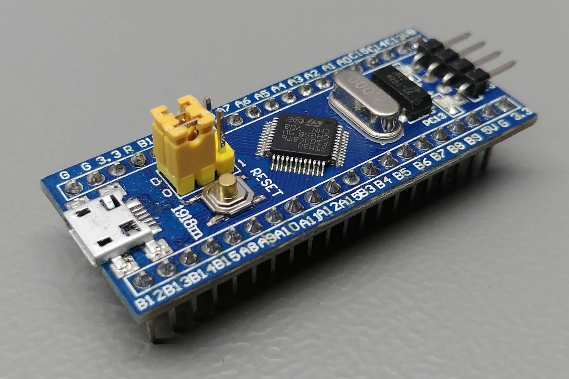
- Task: Using knowledge from Level 1 PCB Design, create a custom STM32 Blue Pill-inspired board. Upgrade it with features like USB-C, additional headers, onboard sensors, or a better regulator. You'll learn to interpret datasheets, manage footprints, and place decoupling caps effectively. Design the schematic in Altium, configure the MCU in STM32CubeMX, and finish the PCB layout considering trace widths, routing strategy, and 2-layer board design rules.
- Platform: Altium and STM32CubeMX
- Expected Task Outcomes:
- Apply real-world PCB design principles to a known microcontroller.
- Integrate firmware design with PCB layout.
- Gain confidence in schematic design, layout, and manufacturing prep.
- Resources:
Concept Spotlight: Microcontroller (Blue Pill)
The Blue Pill is like a mini brain that can sense, think, and act. It controls LEDs, motors, sensors, and more. Designing a custom version teaches you how to build your own smart devices.
Concept Spotlight: Decoupling Capacitor
These are tiny "shock absorbers" that protect the microcontroller from voltage spikes—like giving it a smooth power ride.
3. Digital DNA
- Prerequisite: An elementary understanding of Digital Logic
- Objective: Mastering Verilog Through Creative Circuit Design
- Task: Begin your journey into Verilog HDL by building meaningful projects.
Basics
- Learn the differences between implementation code and testbench code in Verilog.
- Design and test an 8-bit signed arithmetic unit with operations:
- Addition (00)
- Subtraction (01)
- Comparison (10)
- Absolute difference (11)
- Generate 3 status flags: overflow, zero, negative
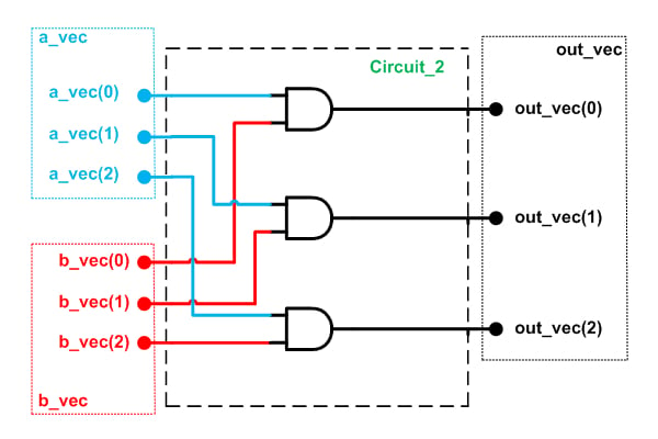
- Design a 2D Population Count Circuit that analyzes a 4×4 binary matrix and provides comprehensive bit counting statistics.
- Design and test a 4-bit Ripple Carry Adder using a Generate Block. Each gate has a Rise, Fall, and Turn-Off Delay of 3ns, 6ns, and 2ns respectively.
- Design and test the Capstone Home Light Automation PLA/PAL from Level 1.
- Bonus Challenge: Design and test a Cellular Automaton of your choice: Rule 90, Rule 110, or 16x16 Conway's Game of Life.
Capstone
Build an alarm system using Verilog and simulate it on a Basys3 FPGA.
- Platform: Intel Quartus Design Suite or AMD Vivado Design Suite.
- Expected Task Outcomes:
- Learn modular and test-driven Verilog design.
- Master simulation/debugging in Quartus or Vivado.
- Build a strong foundation for VLSI, FPGA, and digital logic design.
- Resources:
- nandland
- "Verilog HDL: A Guide to Digital Design and Synthesis", Samir Palnitkar(Beginner to Intermediate)
- "Verilog HDL Synthesis: A Practical Primer",J Bhasker(Intermediate to Advanced)
- ASIC-WORLD
- Verilog Playlist
- HDL Bits
- "Digital Design", Morris Mano, 6th Edition
- Cellular Automaton
- Conway Game of Life
- "Digital VLSI Design with Verilog", John Williams
- The official IEEE Standard for Verilog HDL - Defined in IEEE 1364-2005
Concept Spotlight: Verilog & Testbench
Verilog is a coding language used to "build" digital circuits in software. A testbench is like a practice lab—it tests how your design works before you build it.
Concept Spotlight: Cellular Automaton
These are digital grids that evolve over time by simple rules, producing life-like behaviors. Used in simulations, games, and even biology modeling.
4. The Great Timing Heist
- Prerequisite: Digital DNA Level 2 Task 3
- Objective: Mastering Static Timing Analysis
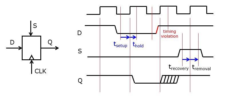
- Task: Delve into Static Timing Analysis (STA) using Intel Quartus or AMD Vivado. Learn key concepts like setup/hold times, slack, and critical paths. Apply this knowledge by analyzing timing reports of a sample design and identifying potential timing violations.
- Platform: Intel Quartus Design Suite or AMD Vivado Design Suite.
- Expected Outcomes:
- Understand STA fundamentals.
- Interpret timing reports effectively.
- Identify and resolve timing issues in FPGA designs.
- Resources:
- AMD STA Guide
- "Digital VLSI Design with Verilog", John Williams, Chapter 17, Week 9 Class 1
Concept Spotlight: Static Timing Analysis (STA)
Imagine checking if every delivery in a relay race makes it on time. STA checks signal timing between digital elements so the circuit doesn’t break at high speed.
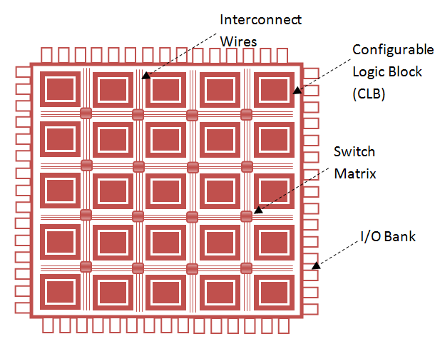
5. Logic Lore
- Prerequisite: Level 1 Task 10 - LUTs
- Objective: Exploring FPGA Architecture
- Task: Understand the following theoretically:
- Basic Xilinx Architecture
- Configurable Logic Block (CLB)
- Switch Matrix
- How they combine with memory to form a basic FPGA tile
- Platform: Theoretical Study
- Expected Outcomes:
- Understand the structure and function of FPGA components.
- Comprehend how CLBs and switch matrices contribute to FPGA flexibility.
- Resources:
- "Digital Design", Morris Mano, 6th Edition
- Xilinx FPGA Architecture
- CLB Video
- Switch Matrix Video
Concept Spotlight: FPGA Tile
A tile is one "cell" in an FPGA grid. Each tile contains configurable logic and routing pathways—like a self-configuring circuit block.
Concept Spotlight: LUT (Look-Up Table)
A LUT stores outputs for every possible combination of inputs—like a digital truth table that makes decisions.
6. Silicon Sandbox
- Prerequisite: Logic Lore Level 2 Task 5
- Objective: To build a simple, single FPGA tile and simulate it using Verilog
- Tasks:
- Design the CLB Module (LUT + D Flip-Flop)
- Design the Switch Matrix (4x4 programmable mux)
- Design the top-level FPGA Tile module
- Write the testbench code and verify the timing diagram.
- Platform: Intel Quartus Design Suite or AMD Vivado Design Suite.
- Expected Outcomes:
- Develop Verilog modules representing FPGA components.
- Understand interconnections within an FPGA tile.
- Simulate and validate FPGA tile behavior.
- Resources: Refer to Tasks 3, 4, and 5
Concept Spotlight: Multiplexer (MUX)
A MUX is like a switchboard—it selects one signal from many and sends it out. A 4x4 programmable mux can connect any of 4 inputs to 4 outputs.
Concept Spotlight: D Flip-Flop
It stores one bit at a time. Think of it like a tiny memory cell triggered by a clock.
7. MOS Whisperer
- Prerequisite: An elementary understanding of MOSFETs and CMOS. Level 1 Task 3
- Objective: To learn Analog VLSI Design techniques
- Tasks:
- Basics:
- Learn the interface of Electric VLSI
- Create a CMOS Inverter using CMOS technology
- Taking it up a notch:
- Draw schematic and layout of a CMOS Operational Amplifier
- Basics:
- Platform: Electric VLSI
- Expected Outcomes:
- Design and simulate CMOS VLSI.
- Understand the physical layout of VLSI circuitas.
- Gain proficiency in using Electric VLSI tools.
- Resources:
- Download Electric VLSI
- Electric VLSI Playlist
- "Design of Analog CMOS Integrated Circuits", Behzad Razavi
Concept Spotlight: CMOS Inverter
The CMOS inverter flips signals (1 to 0, and vice versa). It’s made of two transistors: one pulls the output high, the other low.
Concept Spotlight: Layout vs. Schematic
- Schematic is the map.
- Layout is the physical blueprint for chip fabrication.
8. Keep Calm & ROS On
- Prerequisite: Level 0 Ubuntu Task and a whole lot of Patience
- Objective: To learn and implement basic Robot Operating System 2 topics
- Task:
- Install and set up Ubuntu 22.04 (dual boot or VM) and ROS 2 Humble Hawksbill.
- Learn the basics of:
- Nodes
- Topics
- Publishers
- Subscribers
- Install the Turtlesim simulator and understand its topics
- Write two custom nodes:
- A Publisher Node that sends velocity commands to move the turtle.
- A Subscriber Node that listens to the turtle’s pose and logs the x, y, and theta values.
- Platforms:
- Ubuntu
- VS Code installed on Ubuntu
- Terminal/Terminator
- TurtleSim
- Expected Outcomes:
- Install and configure ROS 2 environment.
- Understand and implement basic ROS 2 communication.
- Develop simple ROS 2 nodes for simulation control.
- Resources:
Concept Spotlight: ROS 2
ROS 2 is like a smart operating system for robots. It helps different parts of a robot "talk" to each other.
Concept Spotlight: Publisher and Subscriber
- The Publisher says things like “move forward!”
- The Subscriber listens and reacts—like a friend taking directions.
