LEVEL 1 D-P-001 TASK REPORT
23 / 3 / 2025
LEVEL 1 D-P-001 TASK REPORT
Mechanical Design
1.Introduction to Engineering Drawing
Orthographic Projections
I understood what orthographic projections are and understood the different reference planes and different types of views while analysing the position of the object.
-
using mini drafter I have illustrated 7 orthographic projections on A2 sheet.The link contains the images of the drawings Link.
-
I have illustrated the isometric projections.The link contains the image of the drawings Link.
2D Drawing In CAD
From the given folder I have drawn the 2d drawings in autocad.
2D Drafting
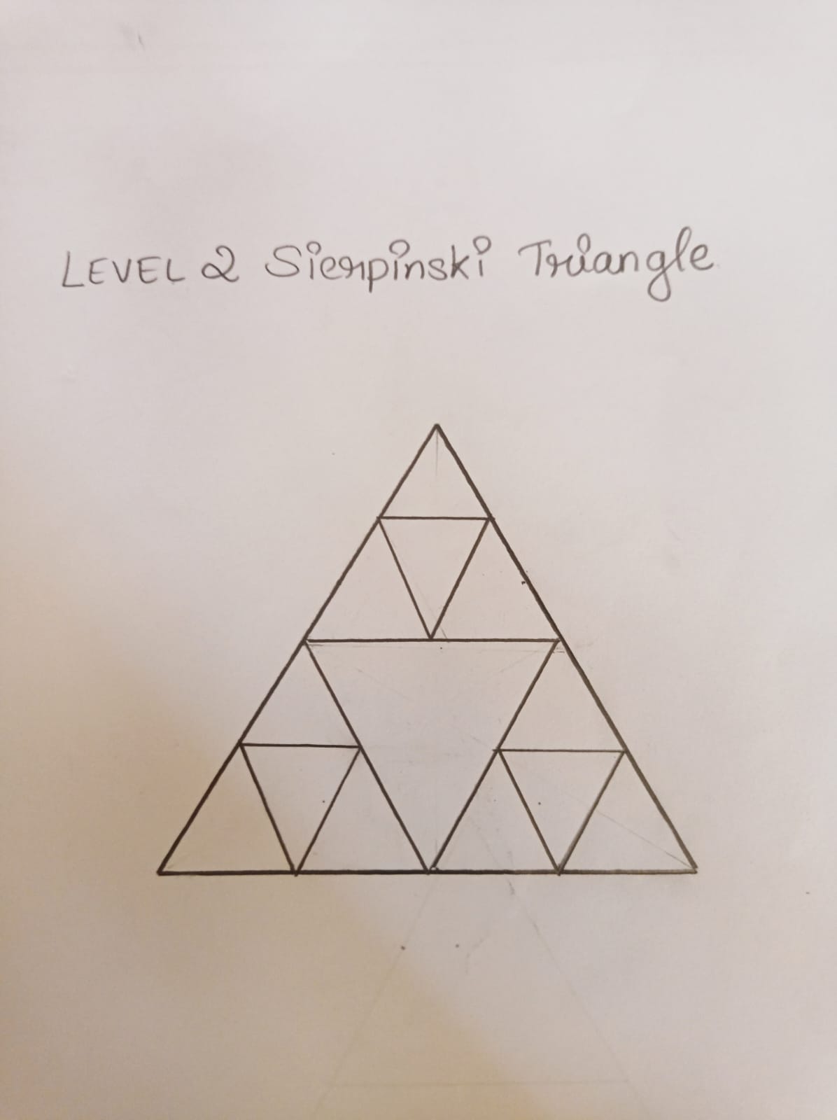
The Sierpiński Triangle is a special pattern made by dividing a big triangle into smaller triangles. This process is repeated, creating a unique design. It is used in computer science, antennas, and art. I have drawn a Level-2 Sierpiński Triangle to show this pattern.
3D Drafting
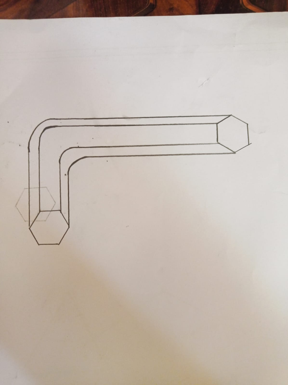
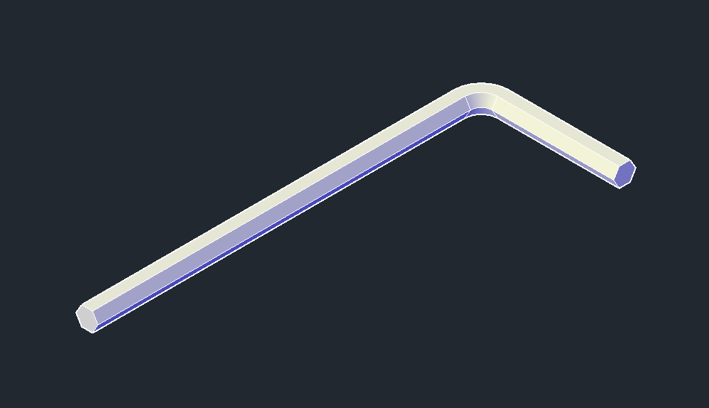
An Allen key is an L-shaped tool used for tightening and loosening hexagonal socket screws. I have created a 2D drawing and a 3D model in AutoCad with dimensions: 55mm length, 20mm width, and 3mm size. I ahve used the sweep tool for the allen key .
Task 2
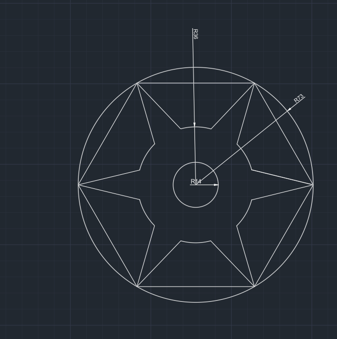
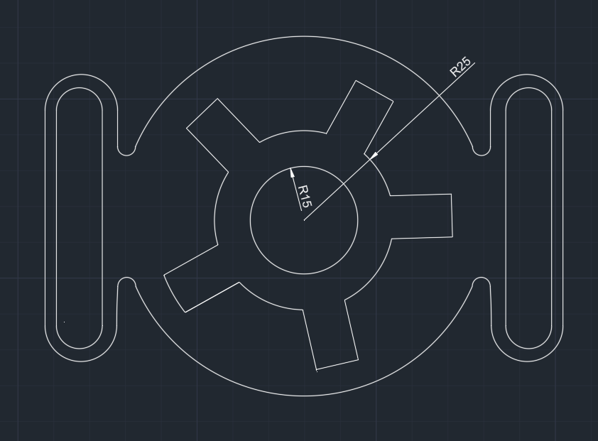
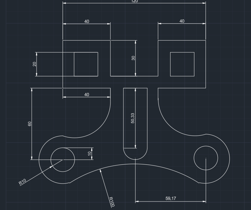
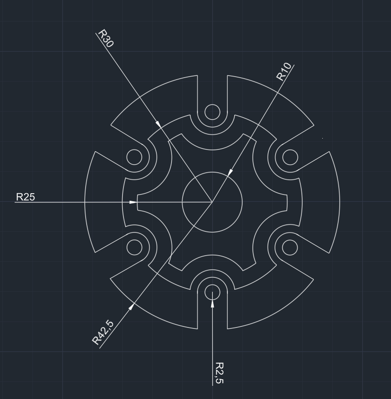
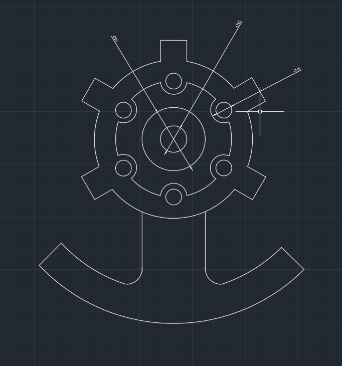
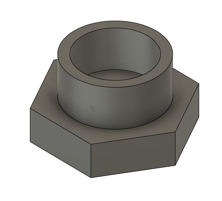
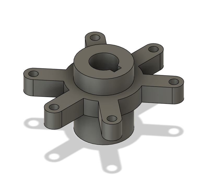
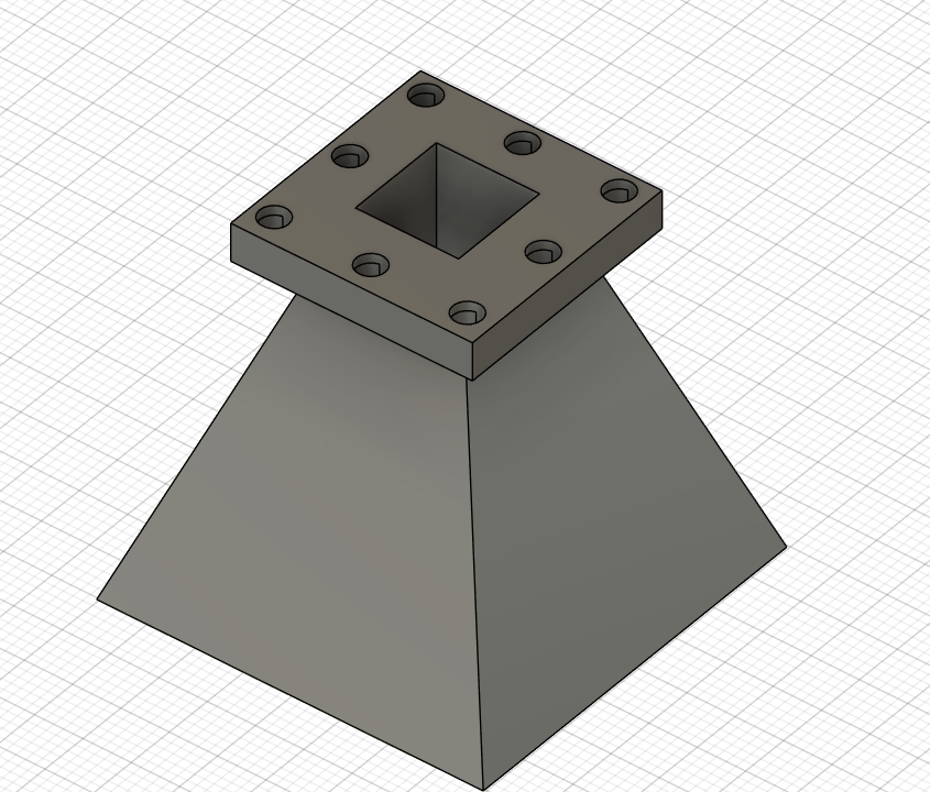
With reference to the drawing I have 3d drafted 3 machine parts in fusion 360. I first made the 2d drawings of the machine part and then used 3d tools like extrude,hole to 3d model the machine parts according to the given dimensions.
2. 3D Modelling
Solid Modelling
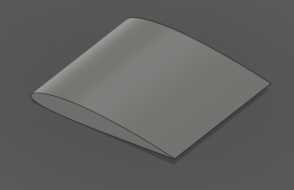
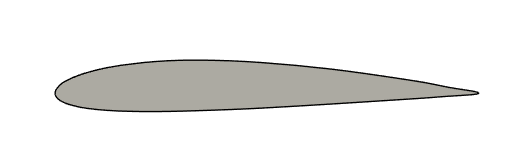
I designed a simple airfoil for a Horizontal Take-Off and Landing (HTOL) aircraft using Fusion 360. To streamline the process, I utilized plug-ins and add-ons to generate a NACA 2412 airfoil profile. Through this, I gained a solid understanding of the NACA airfoil designation system and the significance of its parameters. Additionally, I familiarized myself with the fundamental aspects of airfoil geometry, including the leading edge, trailing edge, and camber line, which are critical to aerodynamic performance and wing design.
Surface Modelling:
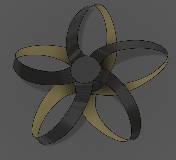
A toroidal propeller is an innovative propeller design in which the blades form a closed-loop or donut-like shape, unlike traditional propellers with straight, outward blades. This unique toroidal geometry helps reduce noise, enhance aerodynamic efficiency, and minimize turbulence. Recognizing its advantages, especially in low-noise applications, I explored this concept further. After understanding its structure and functionality, I applied my knowledge from an introductory course on Forms and Features in Fusion 360, and with the help of the sources provided, I designed a toroidal propeller model.It was a challenging task and also took some time to understand the Forms feature.
Sheet Metal
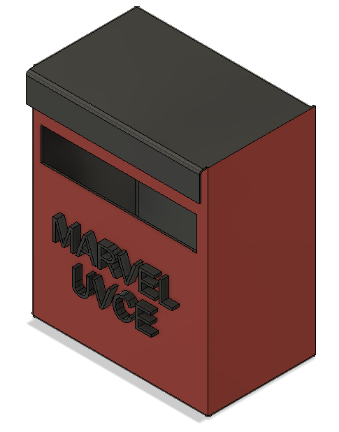
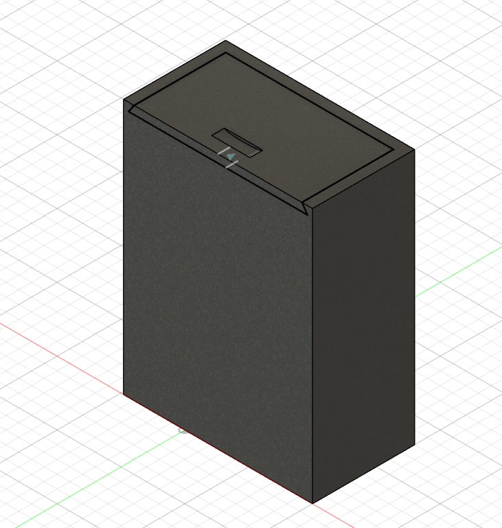
I designed a postbox for MARVEL using the sheet metal environment in Fusion 360, with a thickness of 1 mm and a height of 1 foot (305 mm). I used the flange tool to build the main structure and added features like a mail slot and custom text cutout for branding. The design is easy to manufacture and assemble, with proper bends and clear flat patterns. I focused on making it practical, visually appealing, and efficient in terms of material usage and fabrication.
 .
.
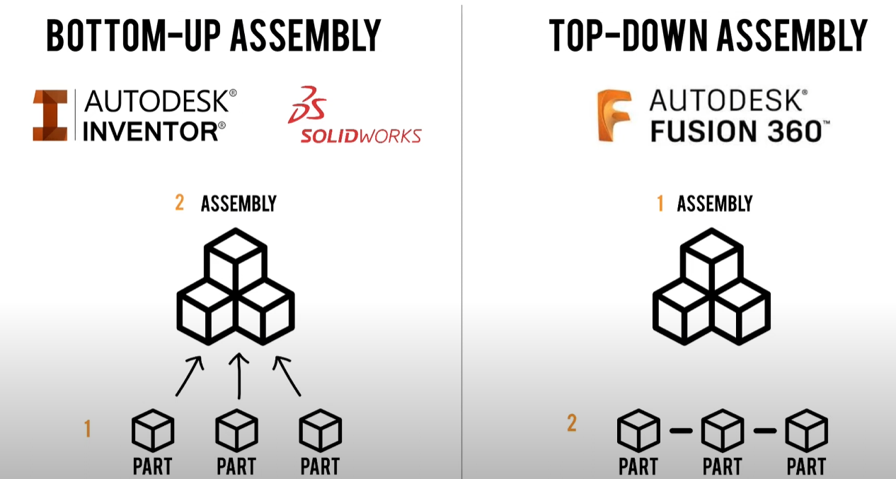
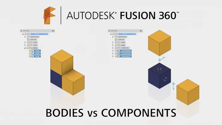
3. Prerequisite for assembly in Fusion 360
After going through the Fusion 360 assembly basics, I now have a better understanding of the difference between bodies and components. I also got a clear idea of the top-down and bottom-up approaches. I learned that bodies are just shapes used for modeling, while components are real parts that can move and be assembled. One important thing I realized is how crucial it is to rename every body and component to avoid confusion later on. I also found that starting with a new component from the beginning helps keep the workflow smoother and more organized. These small steps will definitely save time and make the modeling process a lot easier.
4. Assembly and Animation
I machine Design one of the Mechanisms from scratch from the resources given below. Understanding the basics of modelling, Assembly and Animation Resources.
I have machine designed Ratchet and Pawl Mechanism.below are the imgae of the mechanism and simulation.

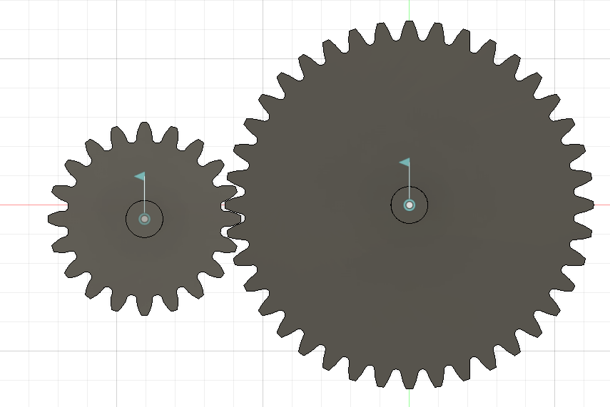
5. Spur Gear Design
I have designed the spur gear based on the provided specifications, including a 2:1 ratio with 20 and 40 teeth for the input and output gears, a 3 mm module, and a 20° pressure angle. The Spur Gear Generator add-in in Fusion 360 was used to create accurate involute tooth profiles. I applied “As-Built Joint” constraints to assemble the gears correctly and further improved the model. A motion link was also added to simulate proper rotational movement between the gears.
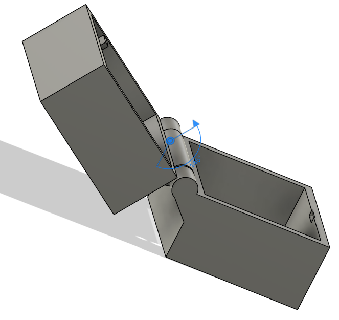
6.Designing a parametric box
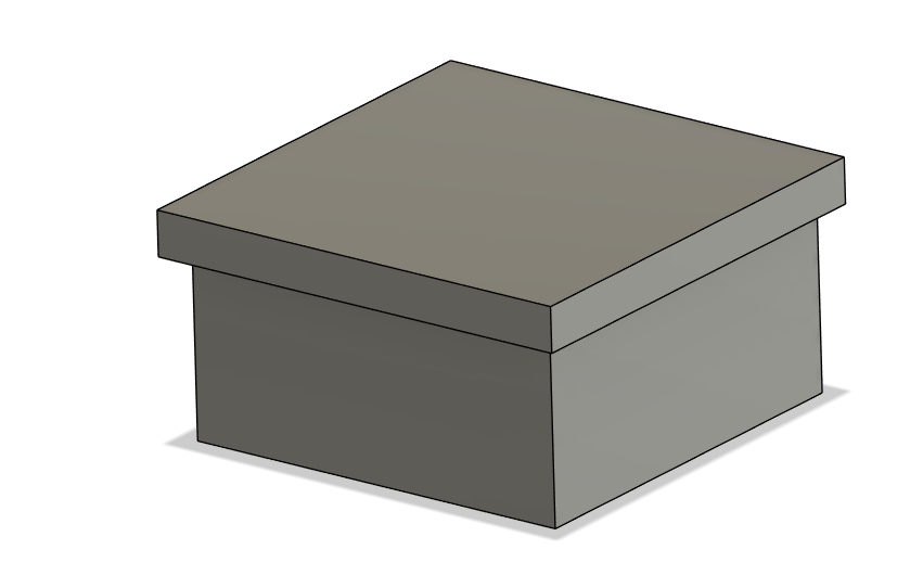
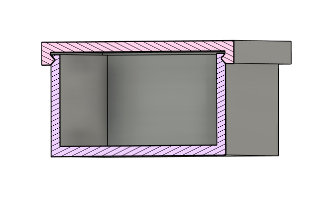
I have designd a parametric box with different kinds of lids with slide,snap,joint and have assembled and animated them.
Electronic Design
1. Cut, Pass, Repeat
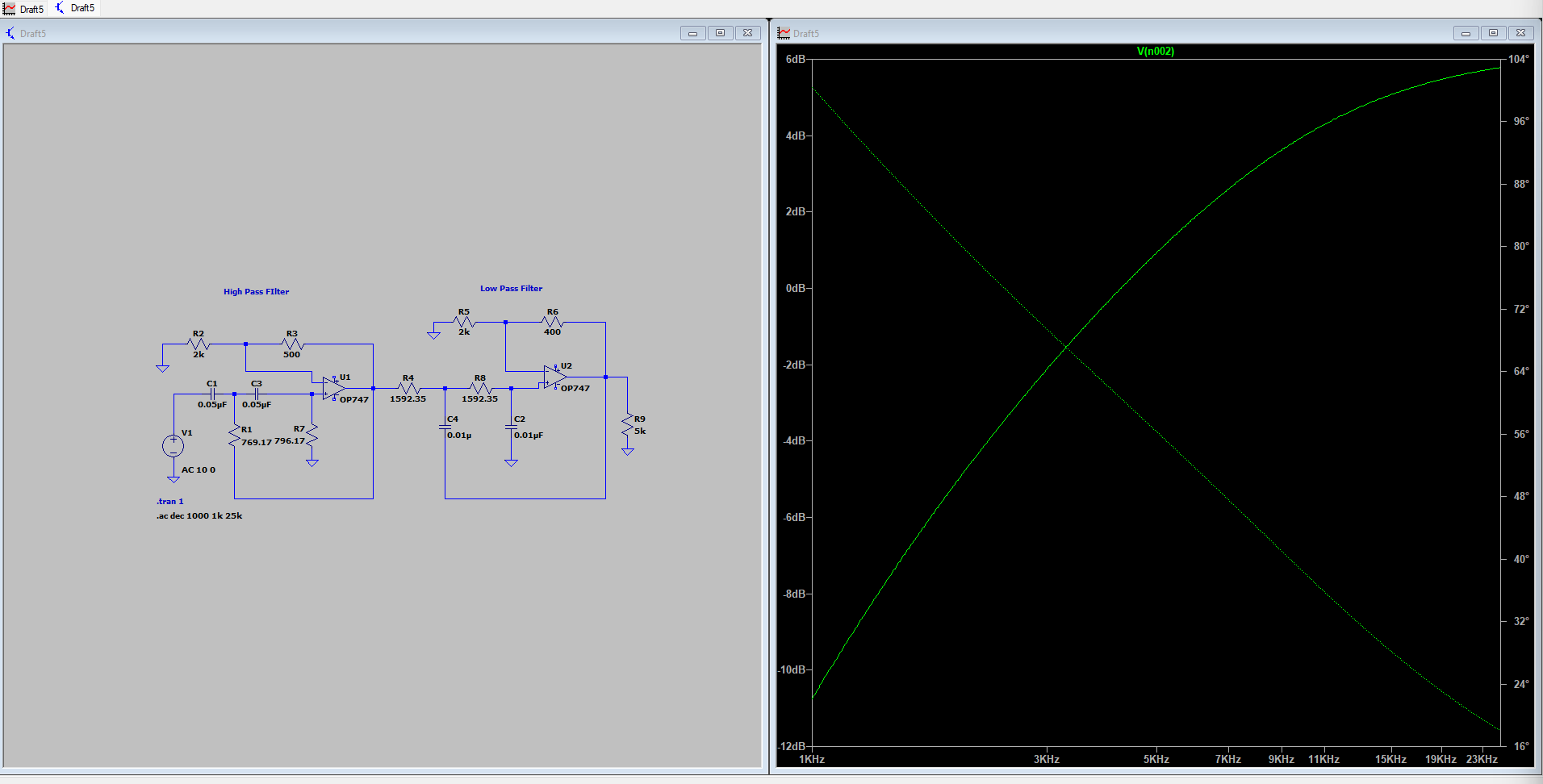
A Band Pass Filter allows signals within a specific frequency range to pass, while attenuating frequencies outside that range.
- High Pass Filter: A high-pass filter allows high-frequency signals to pass through while blocking (attenuating) low-frequency signals.
- Below cutoff frequency → signal is blocked
- Above cutoff frequency → signal passes
- Low Pass Filter:A low-pass filter allows low-frequency signals to pass through while blocking high-frequency signals.
- Below cutoff frequency → signal passes
- Above cutoff frequency → signal is blocked I designed a second-order active band pass filter using the IC747 operational amplifier. The filter amplifies the input signal by approximately 1.5 times and allows frequencies between 4 kHz and 10 kHz to pass, effectively rejecting signals outside this range.
2. SPICEy Code
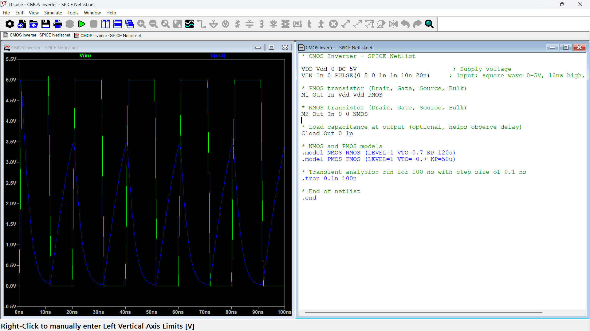
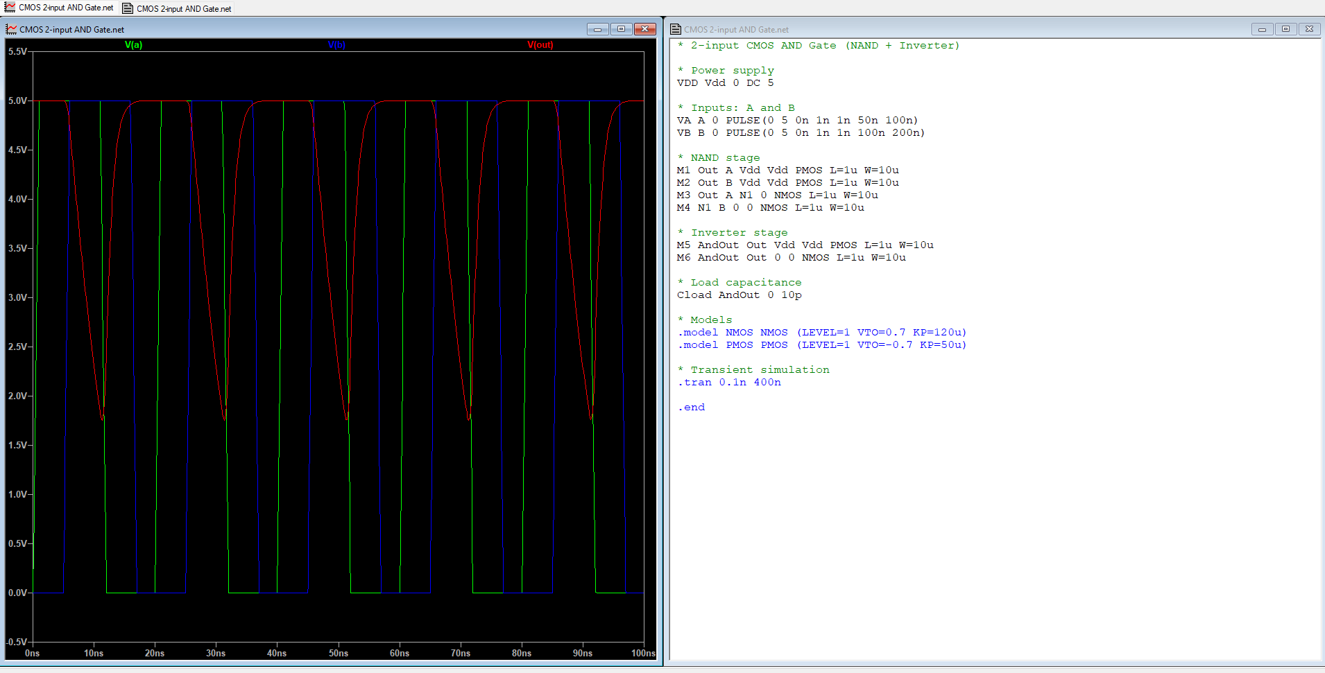
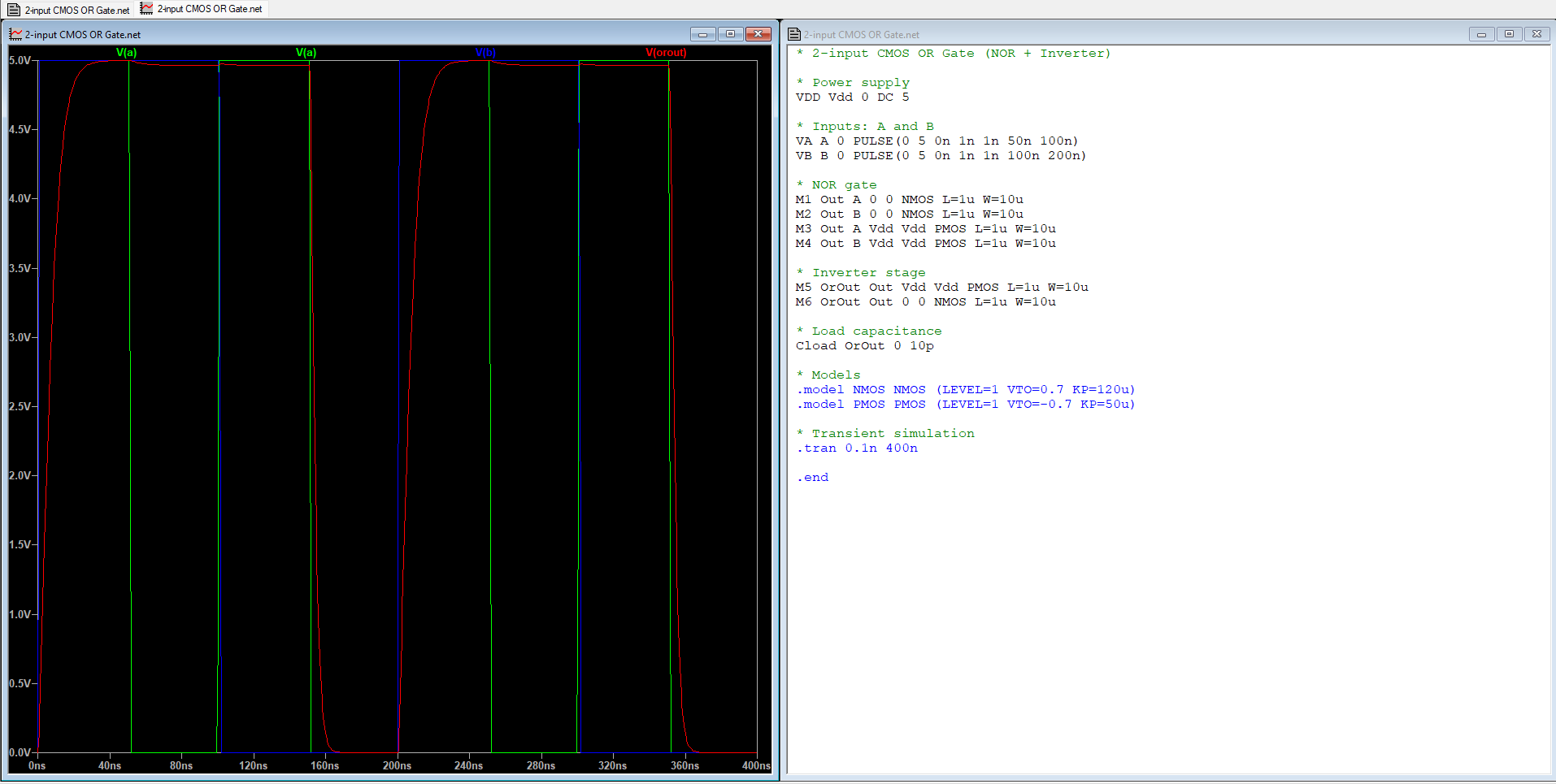
SPICE stands for Simulation Program with Integrated Circuit Emphasis. It is a text-based language used to simulate electronic circuits — especially analog and mixed-signal circuits — at the transistor and system level. or this task, I used SPICE code provided by GPT to create and simulate a CMOS inverter, AND gate, and OR gate in LTSpice. By running these simulations, I was able to see how the transistors work together to produce the correct logic outputs.
CMOS Inverter:
CMOS AND Gate:
CMOS OR Gate:
3. The Power Shuffle: Buck-Boost Edition
A DC to DC converter is a power electronics circuit that efficiently converts a direct current from one voltage to another voltage.
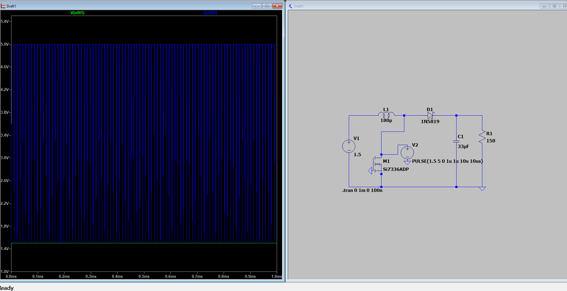
Boost Converters:
Boost converters increase the voltage of a power source. I have built a 1.5V to 5V DC-DC boost converter using the provided resources. The circuit successfully steps up a low DC voltage (1.5V) to a regulated 5V output, making it suitable for powering 5V devices from single-cell batteries.
This type of converter is commonly used in battery-powered electronics such as portable sensors, microcontrollers, and USB-powered devices where a stable 5V supply is required from a low-voltage source.
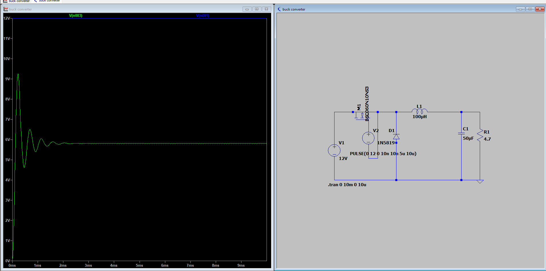
Buck Converters
Buck converters reduce the voltage of a power supply. This is a power electronics circuit that steps down the DC voltage to a level determined by the choice of components in your circuit.
I designed a DC-DC Buck converter that converts 12V to 5v.