
LEVEL 2
1 / 3 / 2024
level 2 report
Task 1 - Watering a Plant
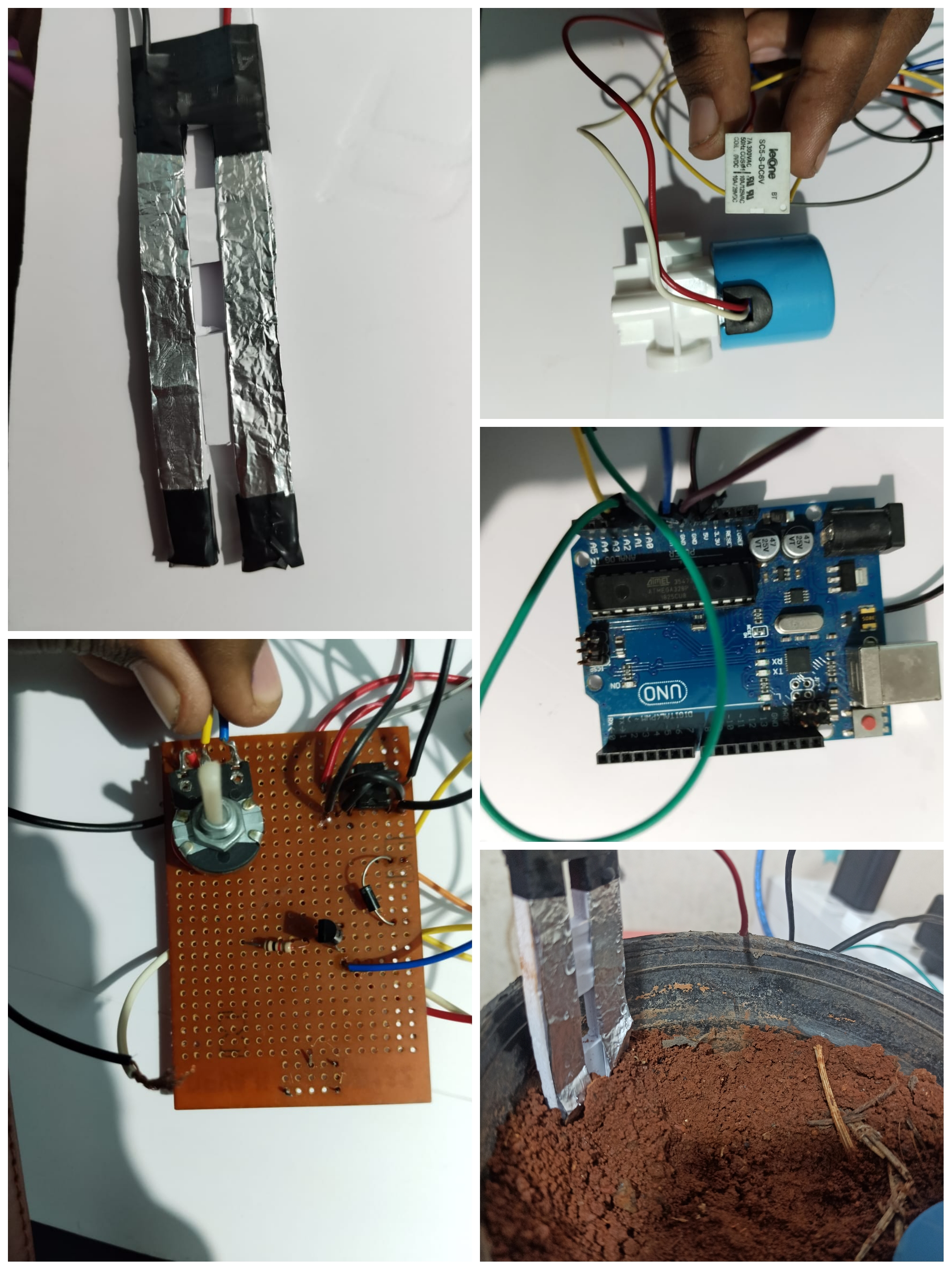
description - Using Solenoid Valve design a system to water the plant when the soil moisture content in the soil goes below a certain threshold value. Use a relay to turn on the valve.
components used
i used an arduino uno as the main controler and soenoid valve to control the water flow . i made a small soil moisture sensor using 555 timer and aluminum foil and i connected the threshold pin to the foil and it behave like a capacitive sensor and when there was rise in moisture of the soil there the 555 timer woul amplify the values and send to arduino uno and i used a relay to control the soenoid valve # Task 2 - Introduction to RFID description - Learn about RFID cards and RFID card reader. Interface it with ESP32 and read a metro card with the reader. Display the hex code on the LCD screen ## components used > 1 MRC522 RFID module > 2 arduino uno1 .Solenoid Valve 2 relay 3 555 timmer 4 arduino UNO
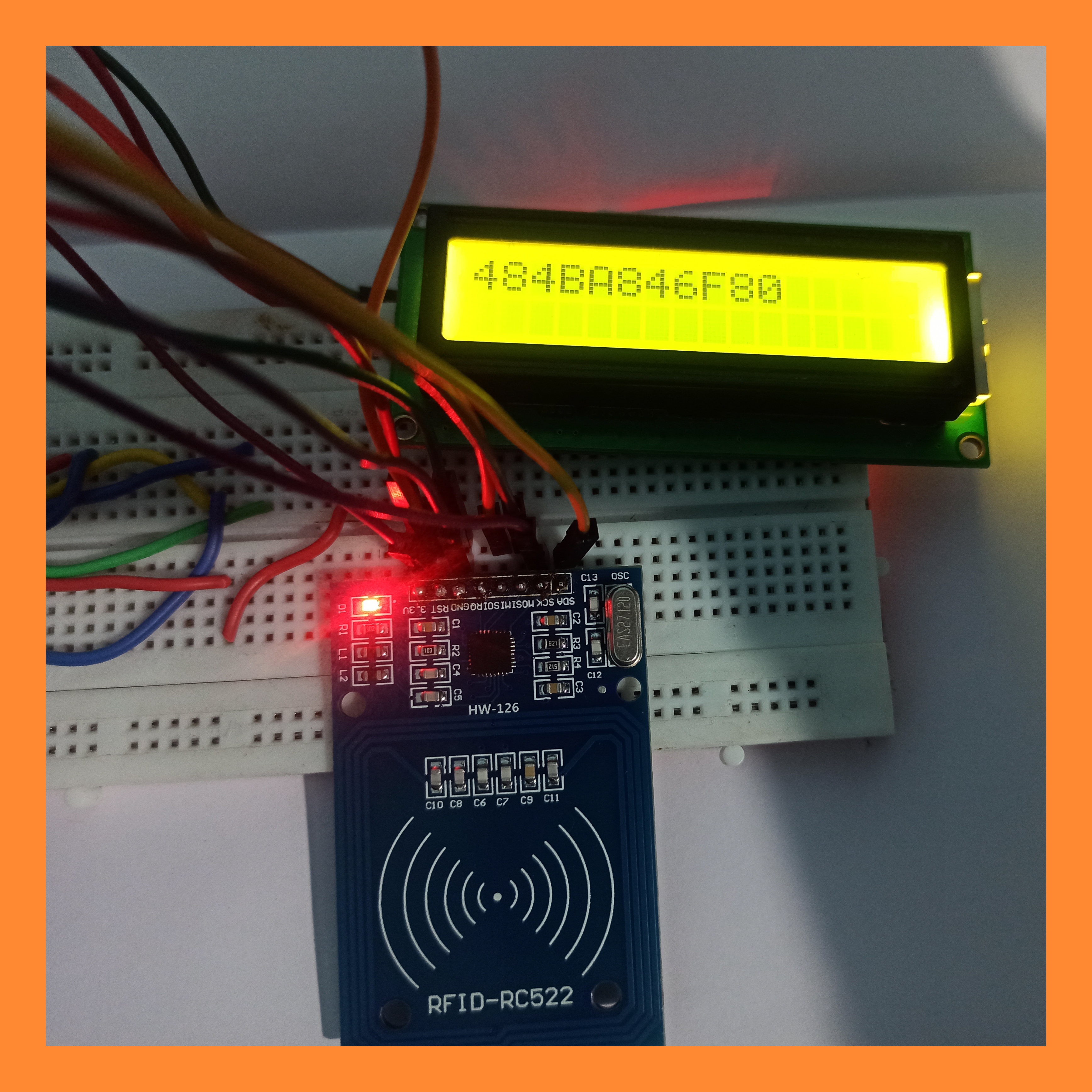
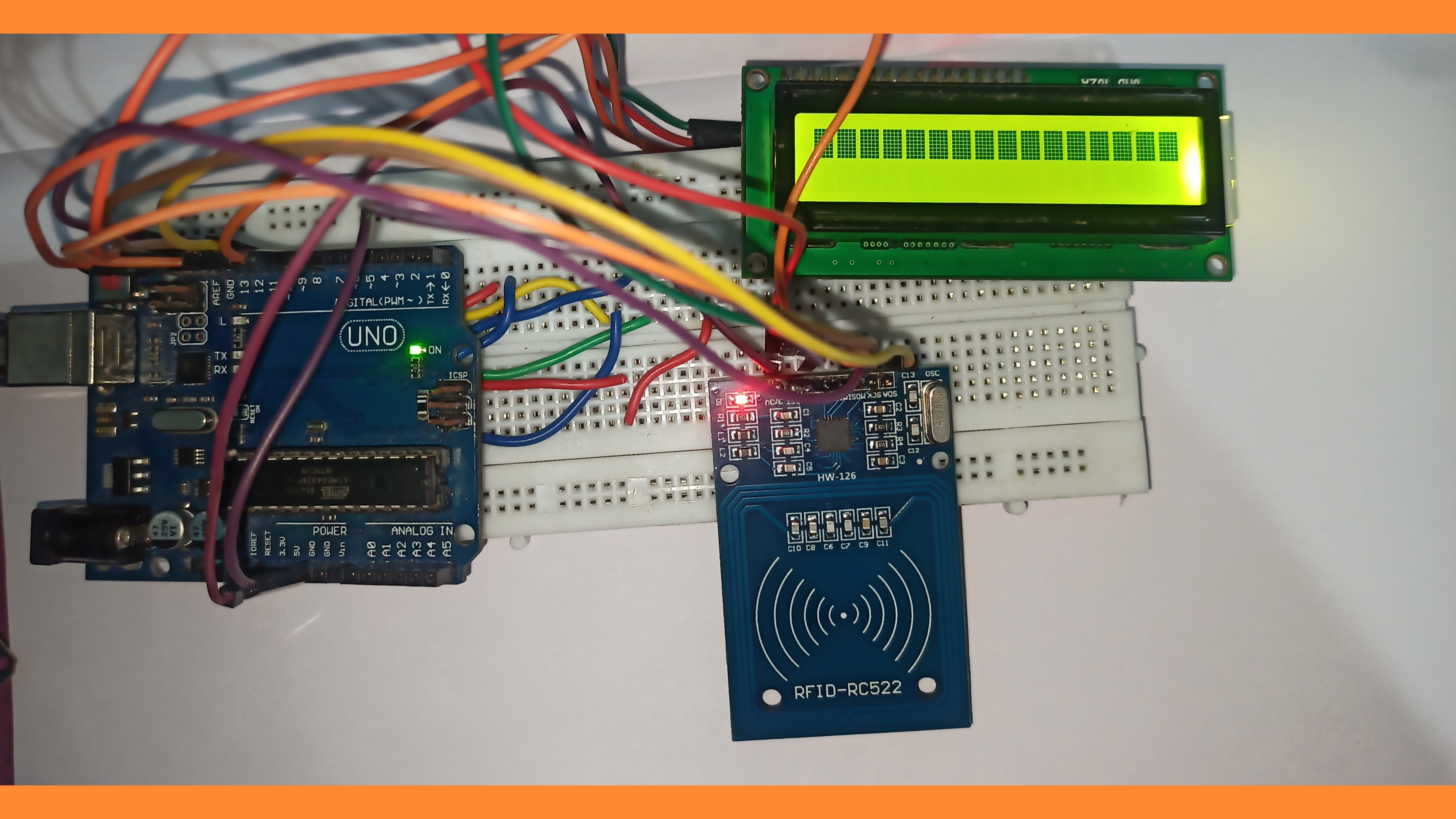
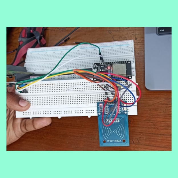
i had to scan a metro card and display its HEX code . i used an arduino as the controller and rfid mudule to scan the HEX code i used the code in the examples and used an lcd to display it3 LCD display(16X2) 4 I2C module
rfid
An RFID or radio frequency identification system consists of two main components, a tag attached to the object to be identified, and a reader that reads the tag.
A reader consists of a radio frequency module and an antenna that generates a high frequency electromagnetic field. Whereas the tag is usually a passive device (it does not have a battery). It consists of a microchip that stores and processes information, and an antenna for receiving and transmitting a signal.When the tag is brought close to the reader, the reader generates an electromagnetic field. This causes electrons to move through the tag’s antenna and subsequently powers the chip.
The chip then responds by sending its stored information back to the reader in the form of another radio signal. This is called a backscatter. The reader detects and interprets this backscatter and sends the data to a computer or microcontroller.
https://lastminuteengineers.com/wp-content/uploads/arduino/Passive-RFID-System-Working.mp4
Task 3 - Interfacing RTC time module with ESP32
description - Interface a DS3231 RTC Module with ESP32 and display the time on the serial monitor.
components used
1 DS3231 RTC Module
2 ESP32
the task was very simple i had to display the current time in the serial monitor i used esp32 as the main controller and an RTC module and i used the code from the examples
RTC module
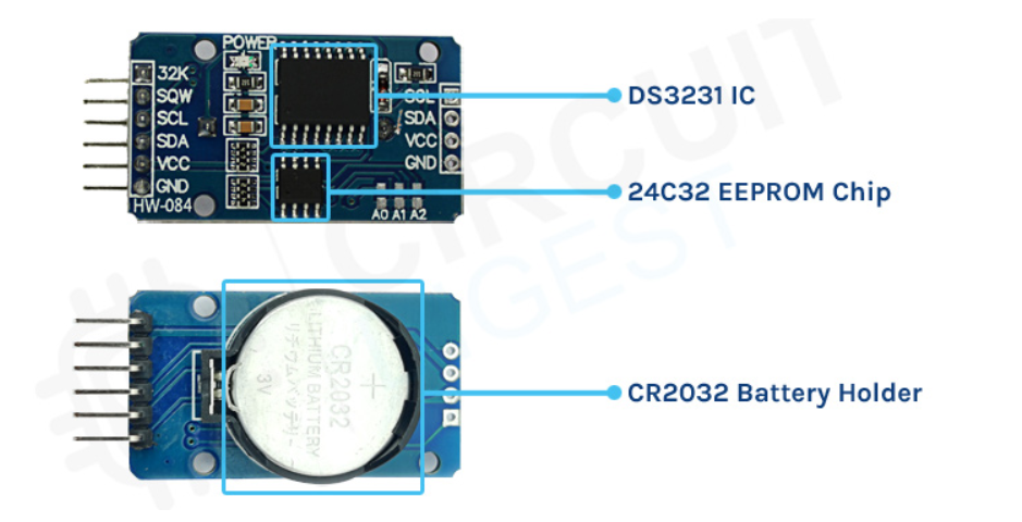
DS3231 RTC Module Introduction The DS3231 is an I2C real-time clock (RTC) with an inbuilt temperature compensated crystal oscillator (TCXO) and crystal that is both low-cost and exceptionally precise. When the module's power is interrupted, the device has a battery input and keeps a precise time. The device's long-term precision is improved by the inclusion of the crystal oscillator. The RTC keeps track of seconds, minutes, hours, days, dates, months, and years. For months with less than 31 days, the date at the end of the month is automatically modified, including leap year corrections. The clock has an AM/PM indication and works in either a 24-hour or 12-hour mode. Two programmable time-of-day alarms are included, as well as a programmable square-wave output. An I2C bidirectional bus is used to transport address and data serially.
Task 4 - Creating an attendance logger
description - Use RFID cards to log in attendance and display the attendance with time on google sheets using IFTTT (Use ESP32).
components used
to demonstrate the process In an educational system, attendance is considered as an important criterion to assess the performance of the student. A student is expected to perform well if he is regular to college. The traditional method of marking the student’s attendance is by calling the student one by one. This method consumes more time. In this technological era, everything is automized. In this tsk we propose a system to monitor and record the attendance of the system using RFID and esp32. Every student will be given unique RFID. When the students scans RFID card in front of RFID card reader, the attendance is automatically marked by reading the RFID tag in the card. It is then stored in google sheets file. Utilizing RFID technology for marking attendance is extremely well effective and saves the time of both the teacher and the student. # Task 5 - Communication using Zigbee protocol description-Establish a communication between Arduino and ESP32 using zigbee protocols and transfer data from a sensor from one device to the other. ## components > 1 ardiuno UNO -2 > 2 xbee S2S module -2 > software used - XCTU 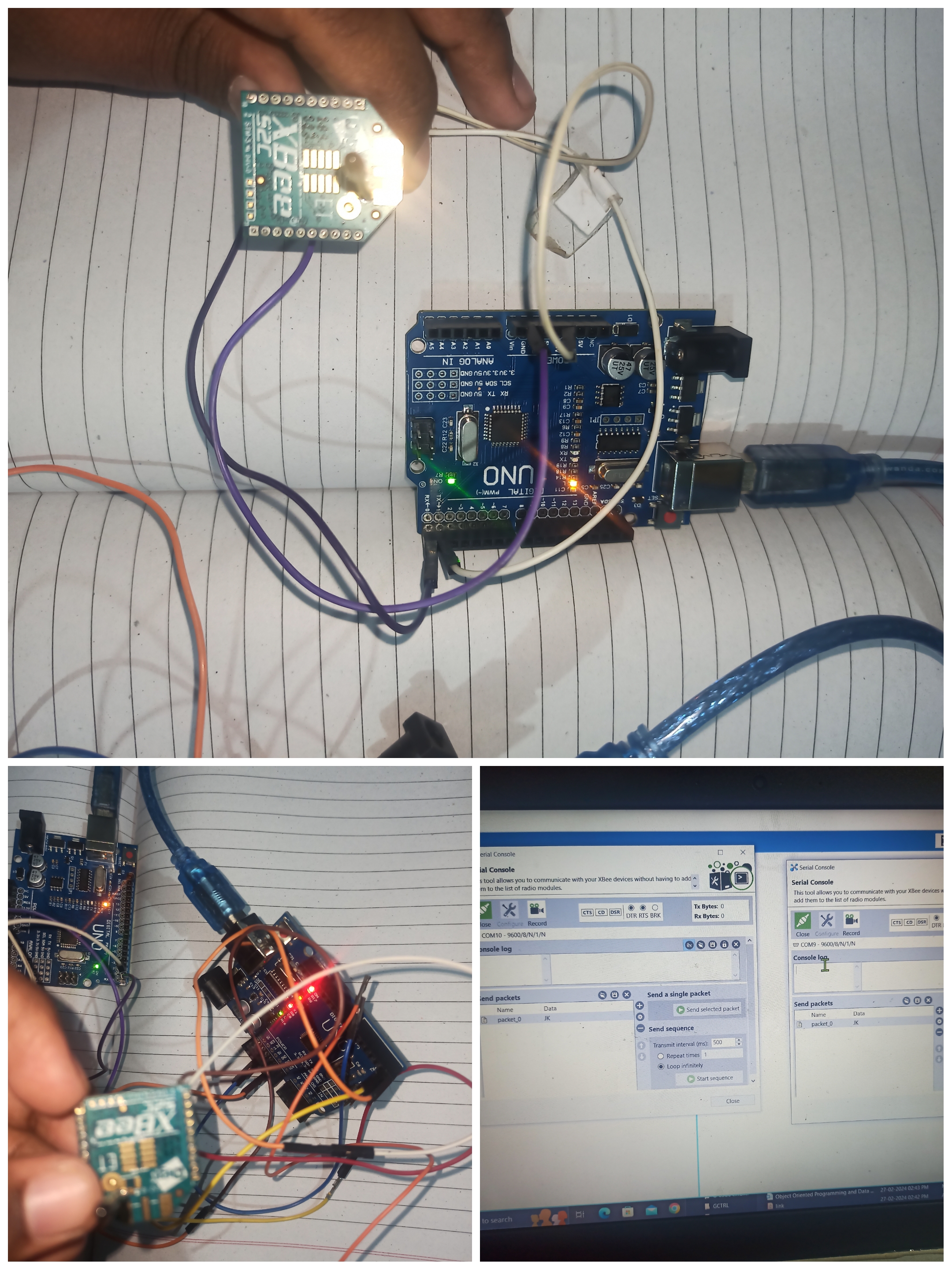 the task which i had to do was to build a communication between two micro controllers using xbee module but i was unable to achieve the expected out put and but i established a communication between two xbee modules and this task was a bit hectic because i had no xbee programmer module and serial communication code had no effect on it1 MRC522 RFID module 2 ESP32 3 LCD display 4 i2c module
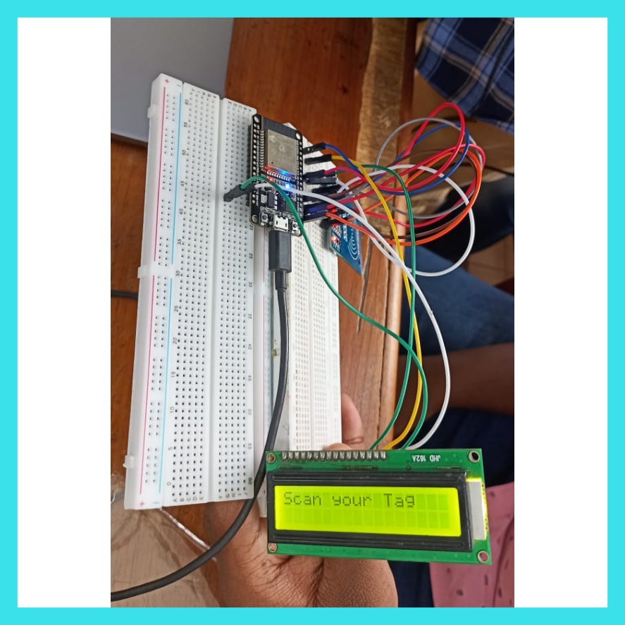
my job was to create a attendance ledger which is wireless and the data gets uploaded automaticaly to google sheets including name time and other personal details i used esp32 as the main controller and using its wifi i can directly send data to google sheets and i used a display
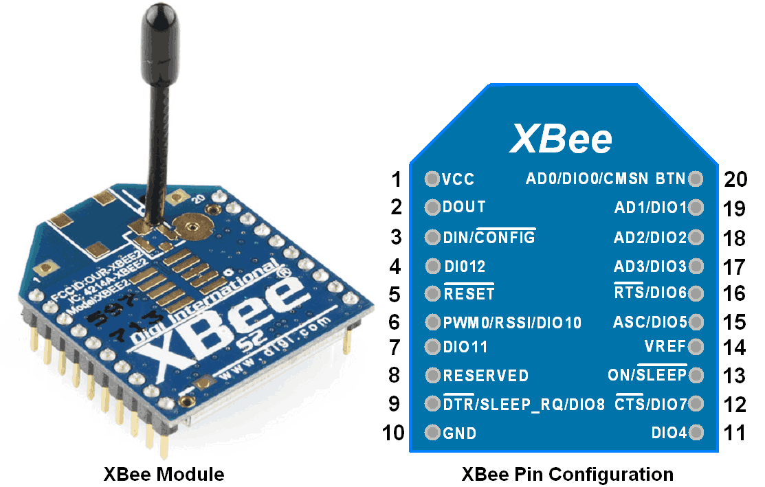
xbee
XBee radio family consist of various XBee RF modules. Each having different specification. Generally, XBee modules operate within ISM 2.4 GHz (Unlicensed) frequency band. XBee modules support ZigBee protocol which is based on IEEE 802.15.4 standard.
XBee modules have source/destination addressing feature with unicast and broadcast communication support. They support point to point, point to multipoint, peer to peer etc. communication topologies.
XBee modules uses DSSS (Direct Sequence Spread Spectrum) modulation technique for communication. XBee has on board features like Digital I/O pins, analog ADC (10-bit) input pins, PWM output etc. It has serial UART pins for communication with PC and Microcontrollers serially. Some XBee modules (e.g. S2C) has support for SPI interface too.
ZigBee Protocol
ZigBee Protocol is based on IEEE (Institute for Electrical and Electronics Engineers) 802.15.4 standards with additional routing and networking functionality. It is used to create Personal Area Network (PAN) using radios. ZigBee has mesh networking functionality. Mesh networking is used where distance between two radios is beyond their ranges
Task 6 - Controlling multiple peripherals using SPI Protocol
description - Using SPI protocol, read from a RFID module and use it to control the direction of DC motor .
components used
1 arduino UNO 2 dc motor 3 L298 motor driver 4 MRC522 RFID module
my task was to use the SPI protocol and control diffrent peripherals. i used RFID module and L298 motor driver as two diffrent perpherals and when rfid card is detected the direction of motor changes
spi
SPI is a common communication protocol used by many different devices. For example, SD card reader modules, RFID card reader modules, and 2.4 GHz wireless transmitter/receivers all use SPI to communicate with microcontrollers.
 One unique benefit of SPI is the fact that data can be transferred without interruption. Any number of bits can be sent or received in a continuous stream. With I2C and UART, data is sent in packets, limited to a specific number of bits. Start and stop conditions define the beginning and end of each packet, so the data is interrupted during transmission.
Devices communicating via SPI are in a master-slave relationship. The master is the controlling device (usually a microcontroller), while the slave (usually a sensor, display, or memory chip) takes instruction from the master. The simplest configuration of SPI is a single master, single slave system, but one master can control more than one slave (more on this below).
One unique benefit of SPI is the fact that data can be transferred without interruption. Any number of bits can be sent or received in a continuous stream. With I2C and UART, data is sent in packets, limited to a specific number of bits. Start and stop conditions define the beginning and end of each packet, so the data is interrupted during transmission.
Devices communicating via SPI are in a master-slave relationship. The master is the controlling device (usually a microcontroller), while the slave (usually a sensor, display, or memory chip) takes instruction from the master. The simplest configuration of SPI is a single master, single slave system, but one master can control more than one slave (more on this below).
Task 7 - Telegram Bot Motor control
description - Create a Telegram bot to turn on a motor in both the directions. Use ESP32 as the interface for this task.
components used
1 dc motor 2 esp32 3 L298 motor driver 4 voltage source
my task was to control dc motor using telegram i used a telegram bot named bot father and its arduino library the code was present in the resource
Telegram allows us to create several bots with different functionalities. For our project, we will be creating a simple bot using Telegram. The rest of the command declarations and replies will be coded in the ESP board itself, which will communicate to our bot using the chat ID. We will discuss those as we proceed further in the article. As that out of the way, we can turn our focus to build the bot in Telegram.
Task 8 - Alexa Light Control
description - By sending voice commands to Alexa turn off or turn on an LED bulb. Use ESP32 for the task
components used
1 esp32 2 relay 3 light 4 voltage source
my task was to control the lights using voice assistant(ALEXA) i used esp rain maker to establish esp as a switch and arelay to control light and interfaced rainmaker app with alexa and google assistant
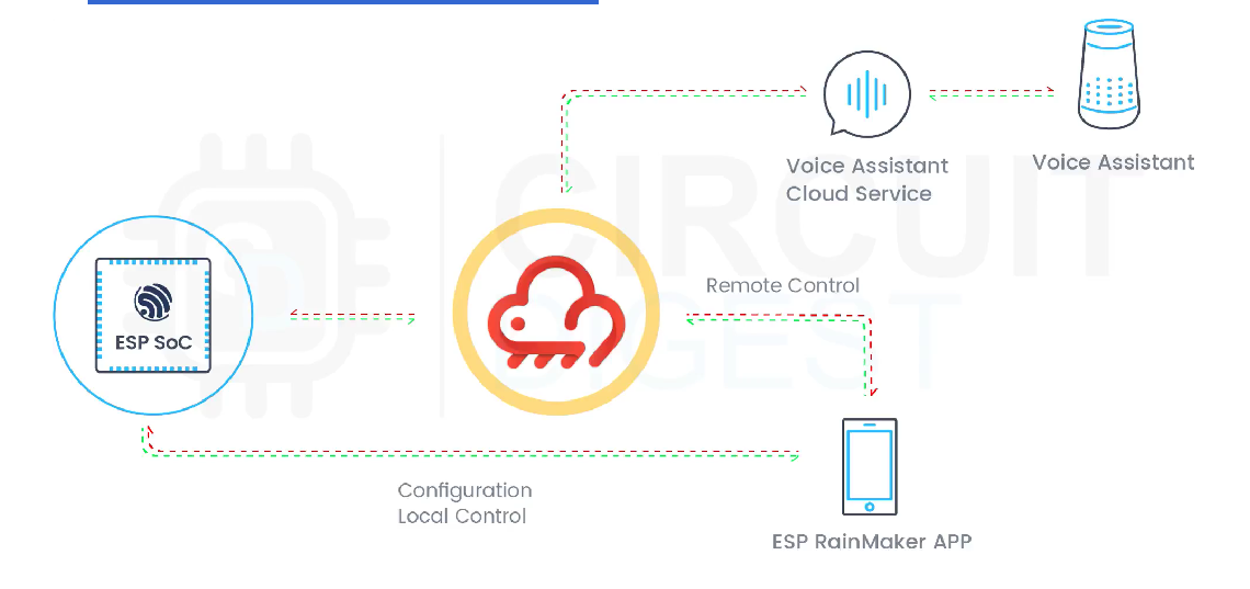
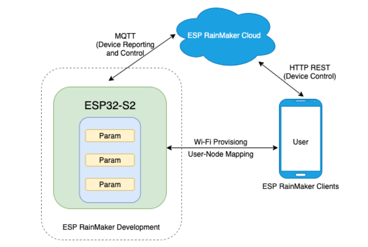
RAINMAKER
ESP RainMaker is the end-to-end platform for the ESP chips from Experessif. It is designed as a successor to Experessif’s ESP Jumpstart platform. ESP RainMaker enables customers to quickly design, build and deploy AIoT solutions based on enterprise-level cloud computing without the hassle of managing any infrastructure. It is a collection of device-agent SDK, a transparent cloud application, and iOS/Android phone apps. This lets developers write the firmware and instantaneously interact with it through the phone apps or voice assistants without writing a single line of code in the cloud or the phone applications. Makers can just focus on developing their firmware without worrying about the app or cloud integration and the rest of the infrastructure.
 The ESP Rainmaker is similar to other IoT services like the Blynk application, Ubidots, Thingspeak, IFTTT, Arduino IoT cloud, etc.
ESP Rainmaker Features and Benefits
A few main features and benefits of the ESP RainMaker platform are as follows:
Minimal R&D investment due to the turnkey solution.
Safe and stable upscale options.
Reduced development time.
Maintenance-free, riskless cloud solution.
Pay-as-you-use solution based on AWS serverless architecture.
Private cloud solution for better security and privacy.
Supports most mainstream services such as Alexa, Google Assistant, Apple Homekit, and Matter.
Node sharing – This allows users to share their device’s control over the internet.
Timezone setting – the timezone of each device or node can be changed through the phone app instead of hard coding.
Arduino Support – ESP rainmaker now supports Arduino IDE, which is great news for the DIY community.
The ESP Rainmaker is similar to other IoT services like the Blynk application, Ubidots, Thingspeak, IFTTT, Arduino IoT cloud, etc.
ESP Rainmaker Features and Benefits
A few main features and benefits of the ESP RainMaker platform are as follows:
Minimal R&D investment due to the turnkey solution.
Safe and stable upscale options.
Reduced development time.
Maintenance-free, riskless cloud solution.
Pay-as-you-use solution based on AWS serverless architecture.
Private cloud solution for better security and privacy.
Supports most mainstream services such as Alexa, Google Assistant, Apple Homekit, and Matter.
Node sharing – This allows users to share their device’s control over the internet.
Timezone setting – the timezone of each device or node can be changed through the phone app instead of hard coding.
Arduino Support – ESP rainmaker now supports Arduino IDE, which is great news for the DIY community.