17 / 8 / 2024
Introduction to RFID
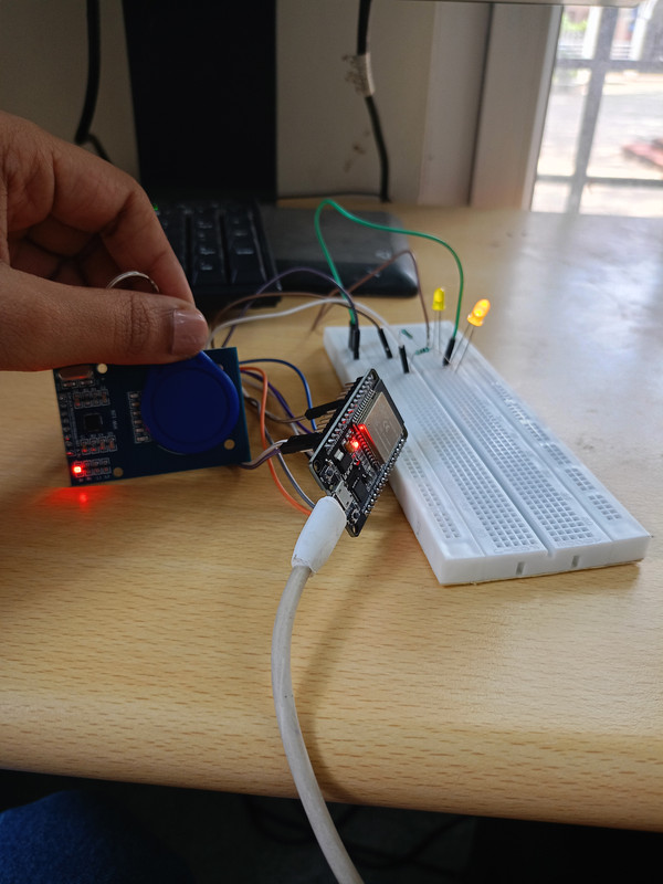
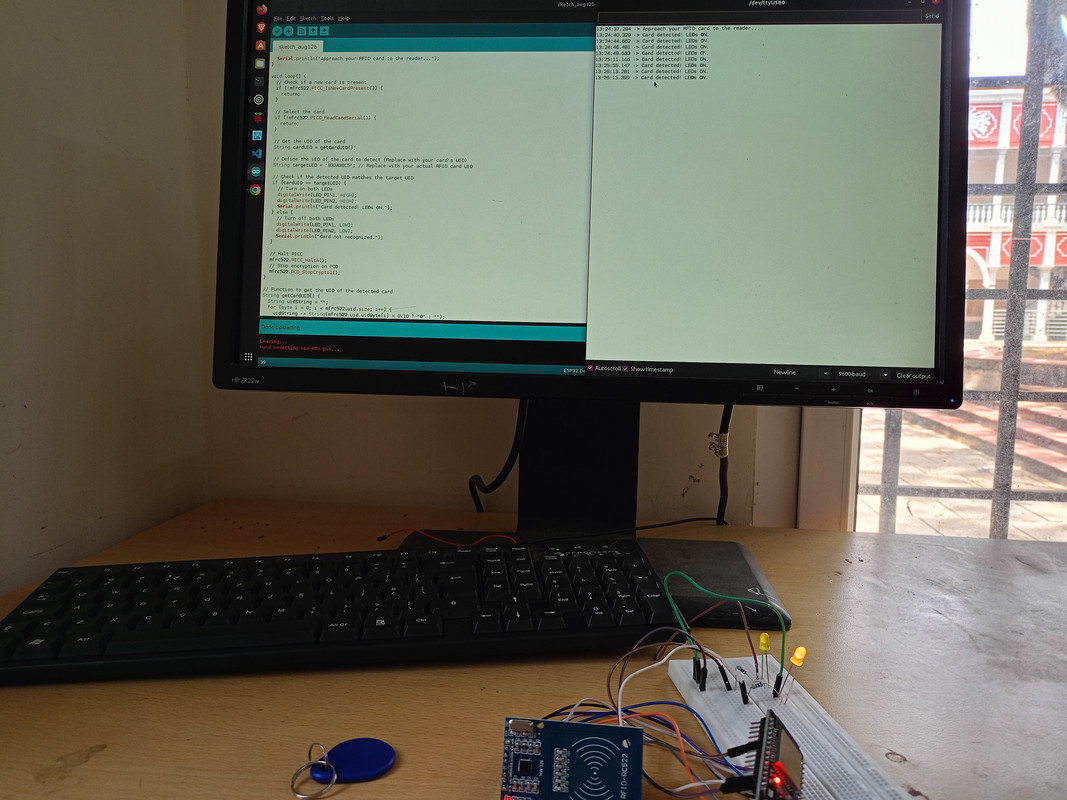
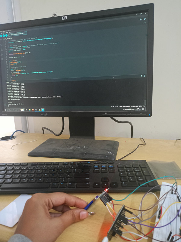
I first went through several articles to gain a basic understanding of RFID technology and how RFID readers communicate with RFID cards. This research helped me familiarize myself with the concepts of radio-frequency identification and how to interface an RFID reader with the ESP32 microcontroller. I faced multiple challenges, particularly in getting the LED to turn on and off correctly when the RFID card was detected by the reader. This part of the project required several attempts and troubleshooting, as the LED wouldn’t respond as expected at first. However, after adjusting the code and testing the circuit, I was finally able to resolve the issue. The project successfully demonstrated how to read RFID cards using an RFID reader and ESP32 and control the LED based on the card detection, providing a clear path from understanding the basics to overcoming technical challenges for a functional outcome.
Interfacing RTC time module with ESP32
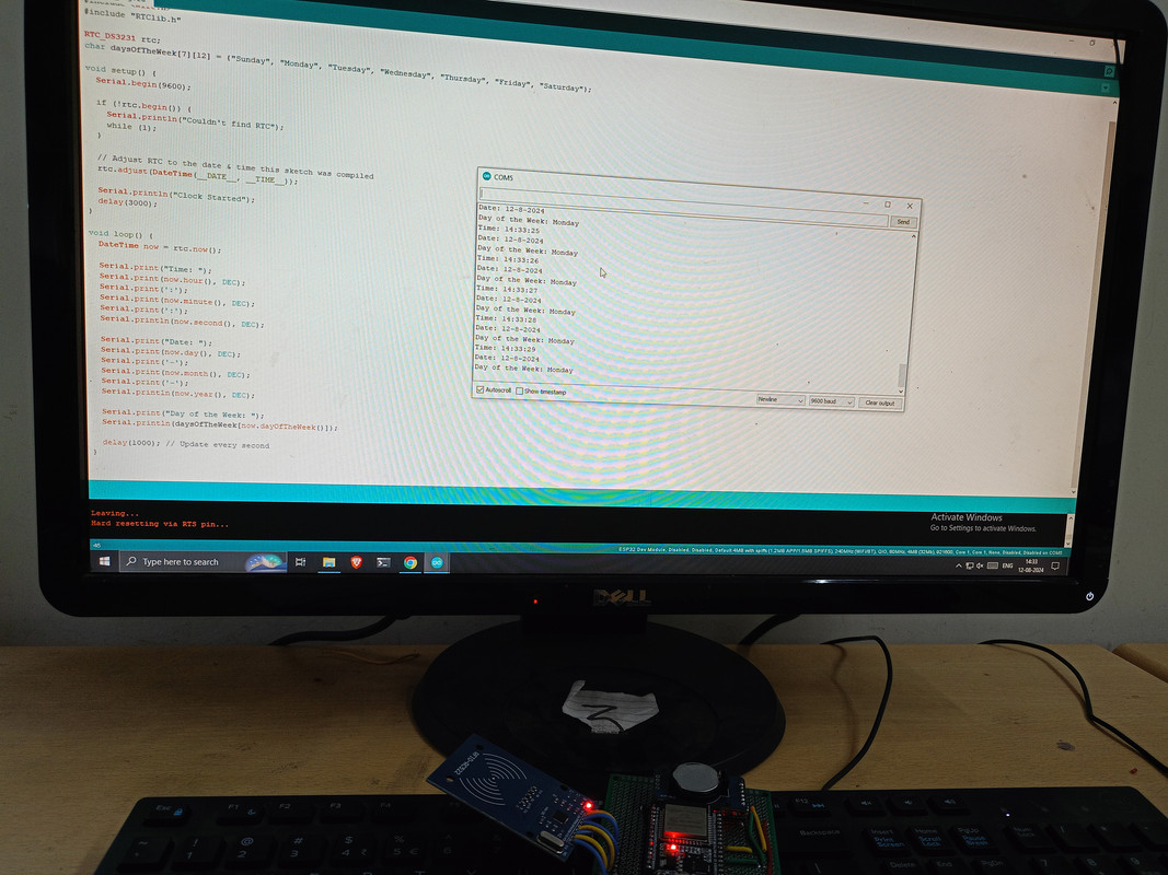
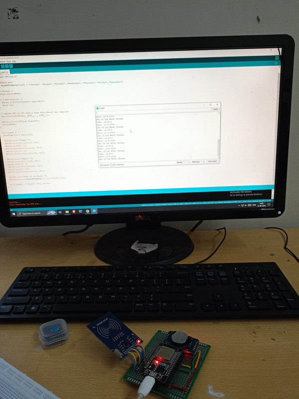
I interfaced a DS3231 RTC (Real-Time Clock) module with an ESP32 to display the current time on the serial monitor. Initially, I went through several articles to understand the working of the RTC module, which maintains accurate time by using a crystal oscillator and stores data even during power loss. The working principles of the DS3231 became clear, and I understood how it communicates with the ESP32 using the I2C protocol.
Setting up the connections between the DS3231 module and the ESP32 was straightforward, as it required just four pins (VCC, GND, SDA, and SCL). The connection process was simpler compared to other tasks I’ve worked on. After wiring the module to the ESP32, I wrote the code to retrieve the real-time data from the RTC and display it on the serial monitor.
Displaying the real-time data was particularly interesting, as I could observe the precise timekeeping function of the DS3231 in action. Overall, this project gave me valuable insights into working with RTC modules and reinforced my understanding of time-based projects with microcontrollers.
Create a Telegram bot to turn on a motor in both the directions
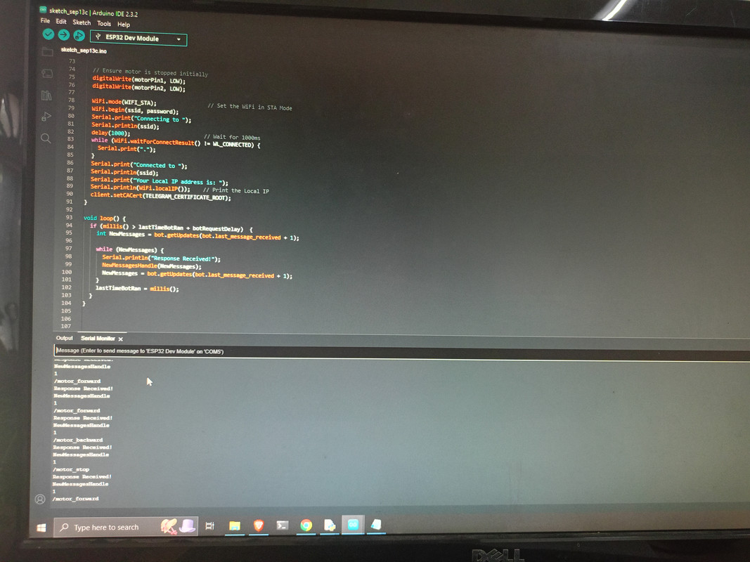
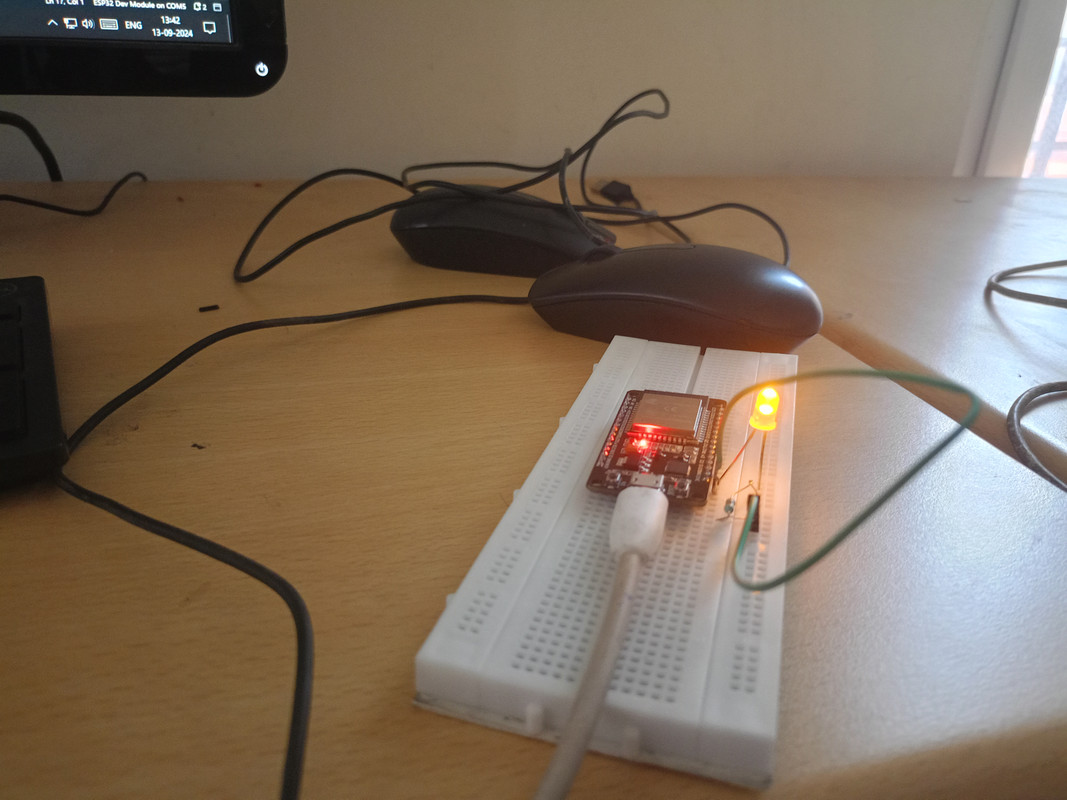
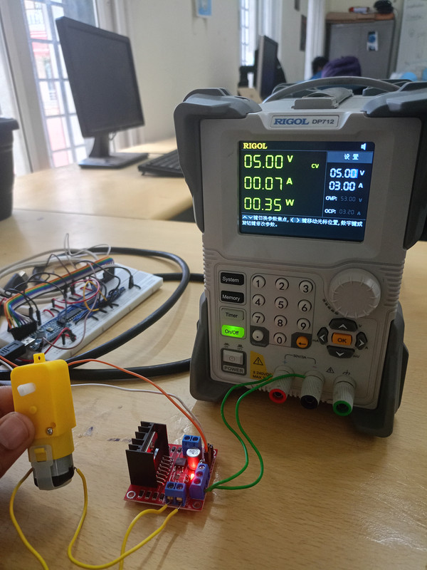
In this project, I created a Telegram bot to control a motor in both directions using the ESP32 microcontroller. The bot serves as an interface to send commands that allow users to turn the motor on, off, or change its direction. Initially, I experimented with controlling an LED through the Telegram bot. This gave me a good understanding of how to send commands from the Telegram app to the ESP32, and after successfully controlling the LED, working with the motor became easier.I used an H-bridge motor driver to control the motor’s direction. The motor driver allowed me to send signals from the ESP32 to turn the motor in both forward and reverse directions. Controlling the motor was similar to the LED in terms of code logic, but it required managing the motor driver’s inputs. The H-bridge motor driver controls the motor’s polarity based on the signals it receives, allowing for direction control. The ESP32 sends high or low signals to the motor driver’s input pins to switch the motor's direction. By setting up separate commands for forward and reverse movement, I was able to control the motor completely through Telegram. The project successfully demonstrated a modern, remote-controlled system where commands could be sent wirelessly to control hardware, showcasing the potential of combining IoT with messaging platforms like Telegram.
Controlling multiple peripherals using SPI Protocol
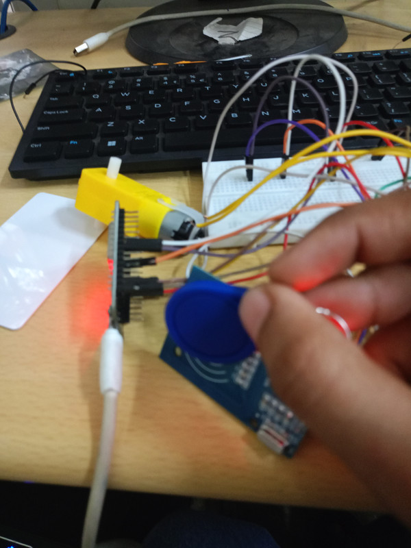
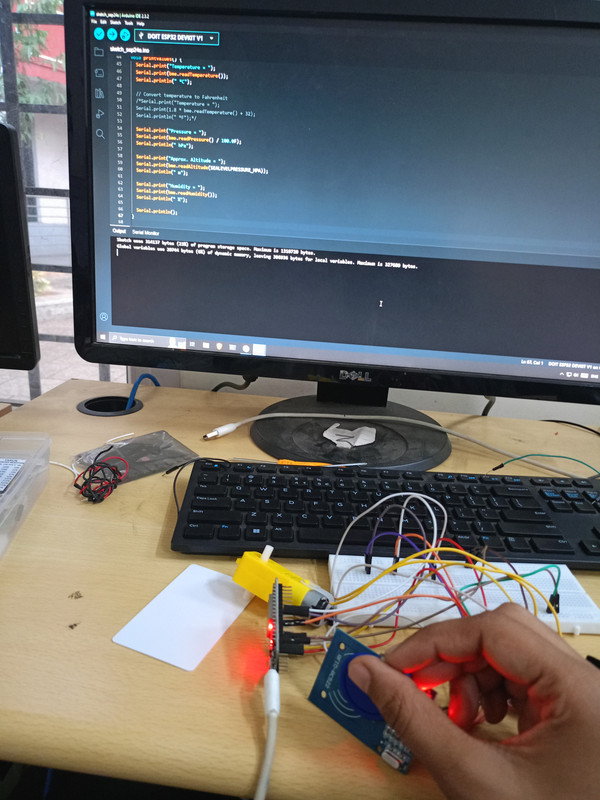
I attempted to use the SPI (Serial Peripheral Interface) protocol to read data from an RFID module and use the RFID card data to control the direction of a DC motor. Having previously worked with RFID and motor control in separate projects, including using a Telegram bot to control a motor, I was confident in combining both elements into this new challenge. However, despite my efforts, I faced difficulties in fully integrating the RFID data with motor control, and I am looking forward to revisiting this project to achieve a successful output.
The SPI protocol requires precise wiring and setup, with connections for the SCK (clock), MISO (master in, slave out), MOSI (master out, slave in), and SS (slave select) lines, in addition to power and ground. The RFID reader detects a card and sends the card’s UID (Unique Identification Number) to the ESP32. The plan was to map specific RFID card UIDs to different motor directions, such that when a card was scanned, the corresponding direction of the motor (forward or reverse) would be triggered.
Creating an attendance logger
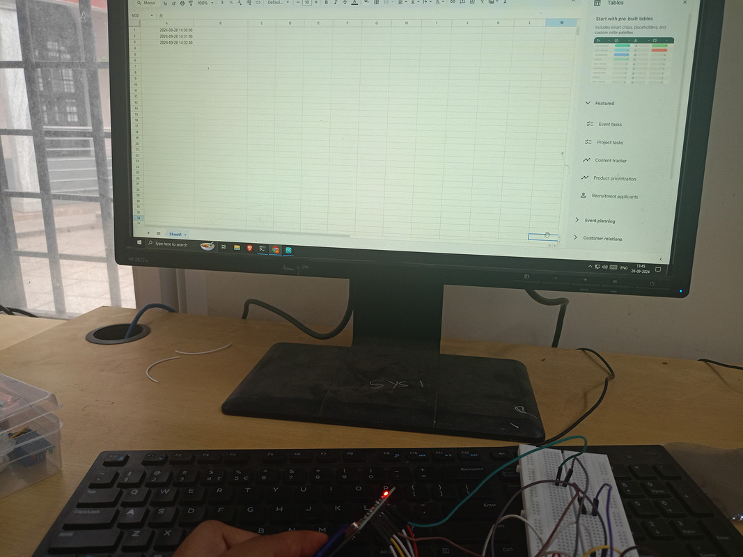
I aimed to create an attendance logger using an RFID module and ESP32. Initially, I tried using IFTTT (If This Then That) to log the attendance data to a Google Sheet, as IFTTT allows easy integration between devices and services. However, I encountered a limitation with the free version of IFTTT, which restricted some of the features needed for logging data effectively. It required a paid version to unlock the full functionality, and despite multiple attempts, I was unable to complete the task with IFTTT.
Automated Plant Watering System Using Solenoid Valve and Soil Moisture Sensor
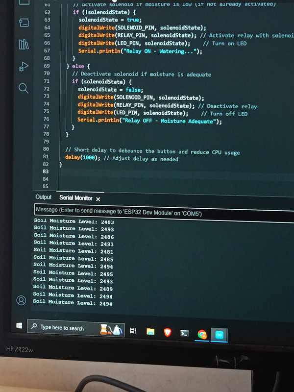
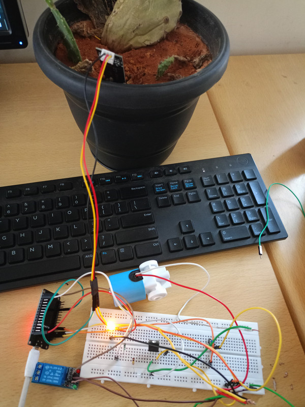
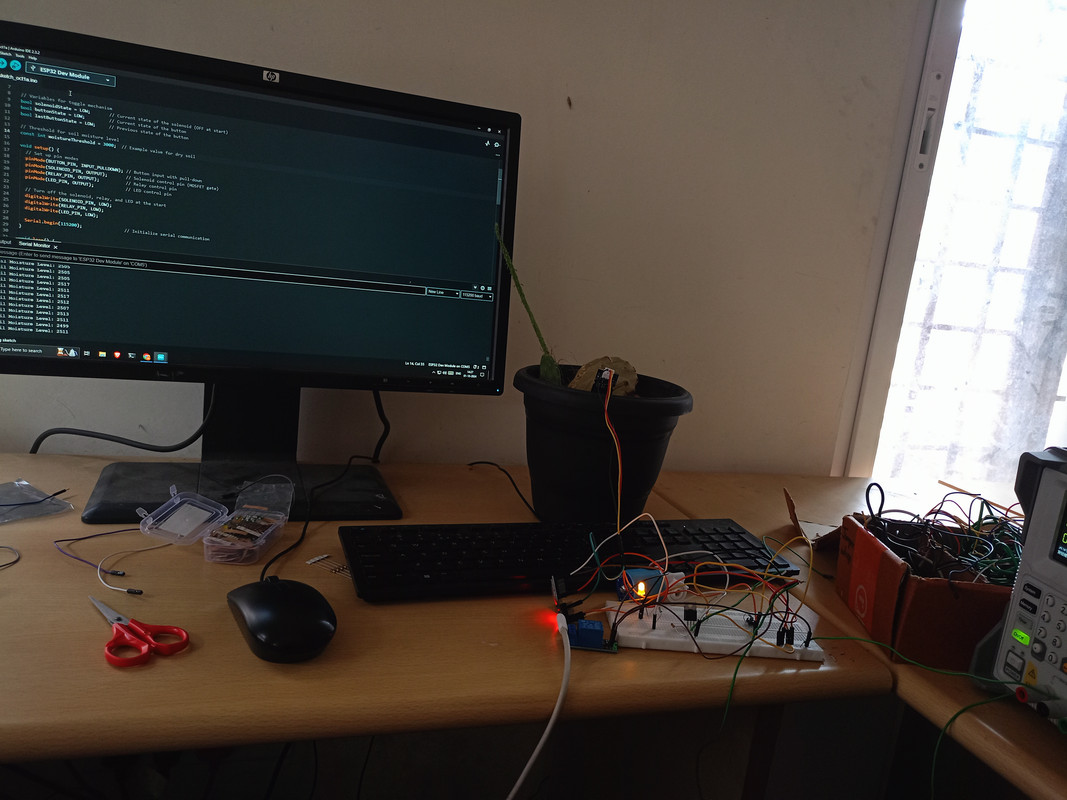
In this project, I designed an automated system that waters plants based on soil moisture levels. When the moisture content drops below a set threshold, the system activates a solenoid valve to water the plant. The relay controls the on/off operation of the solenoid valve. The soil moisture sensor continuously monitors the moisture level in the soil. When the moisture level drops below the defined threshold, the microcontroller sends a signal to the relay. The relay activates, opening the solenoid valve, allowing water to flow to the plant. Once the desired moisture level is reached, the valve closes. Conclusion: The system successfully automates plant watering, reducing manual intervention and ensuring optimal plant health. Future iterations could incorporate IoT for remote monitoring and control.

