
23 / 10 / 2025
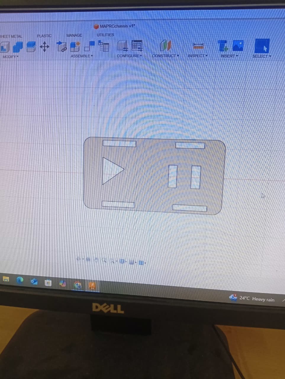
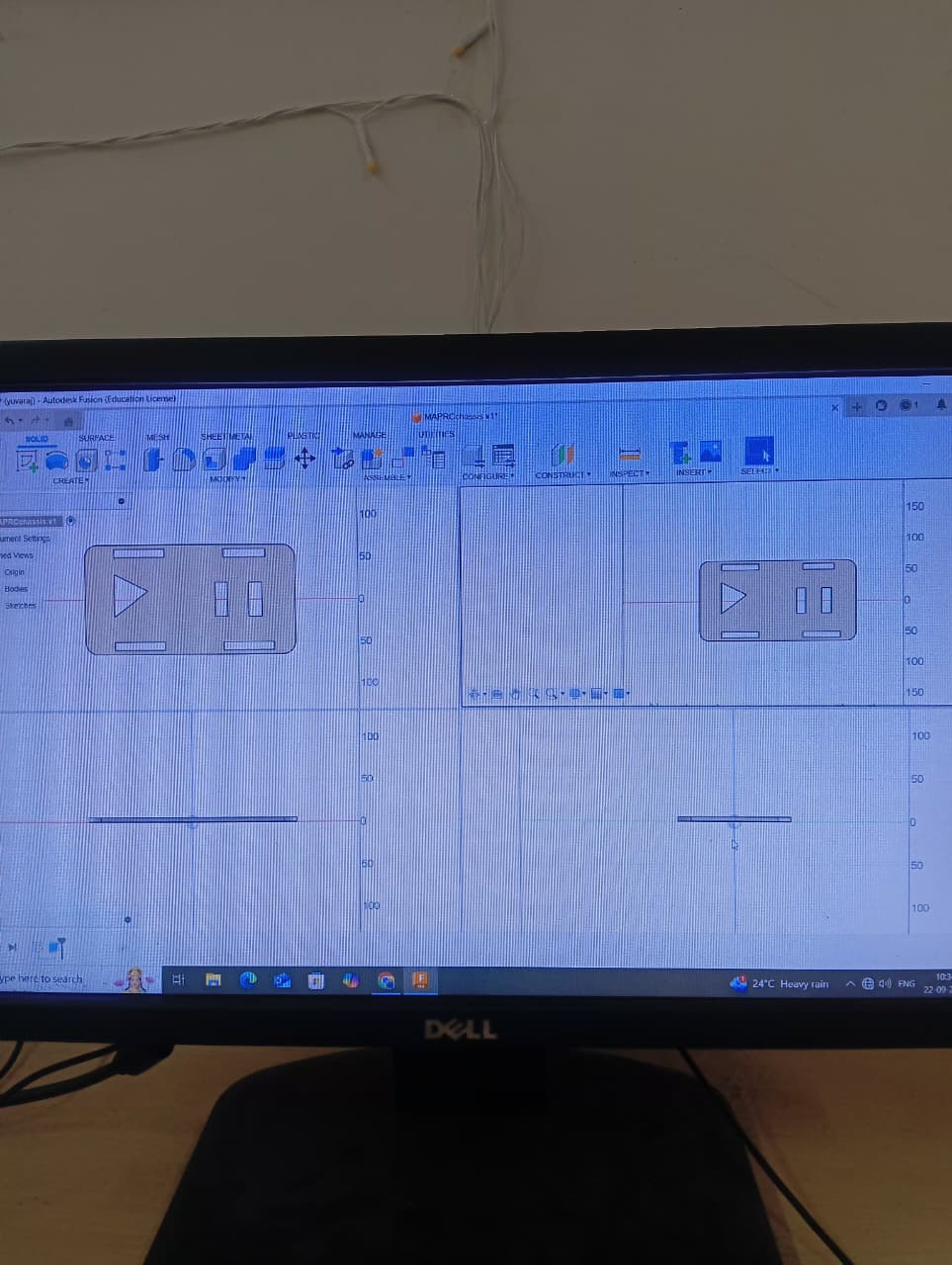
TASK 1 : CAR CHASIS DESIGN
This task involves designing a car chasis using CAD design software.
RESULT AND OUTCOMES
Learned to use fusion 360 for designing basic stuff.
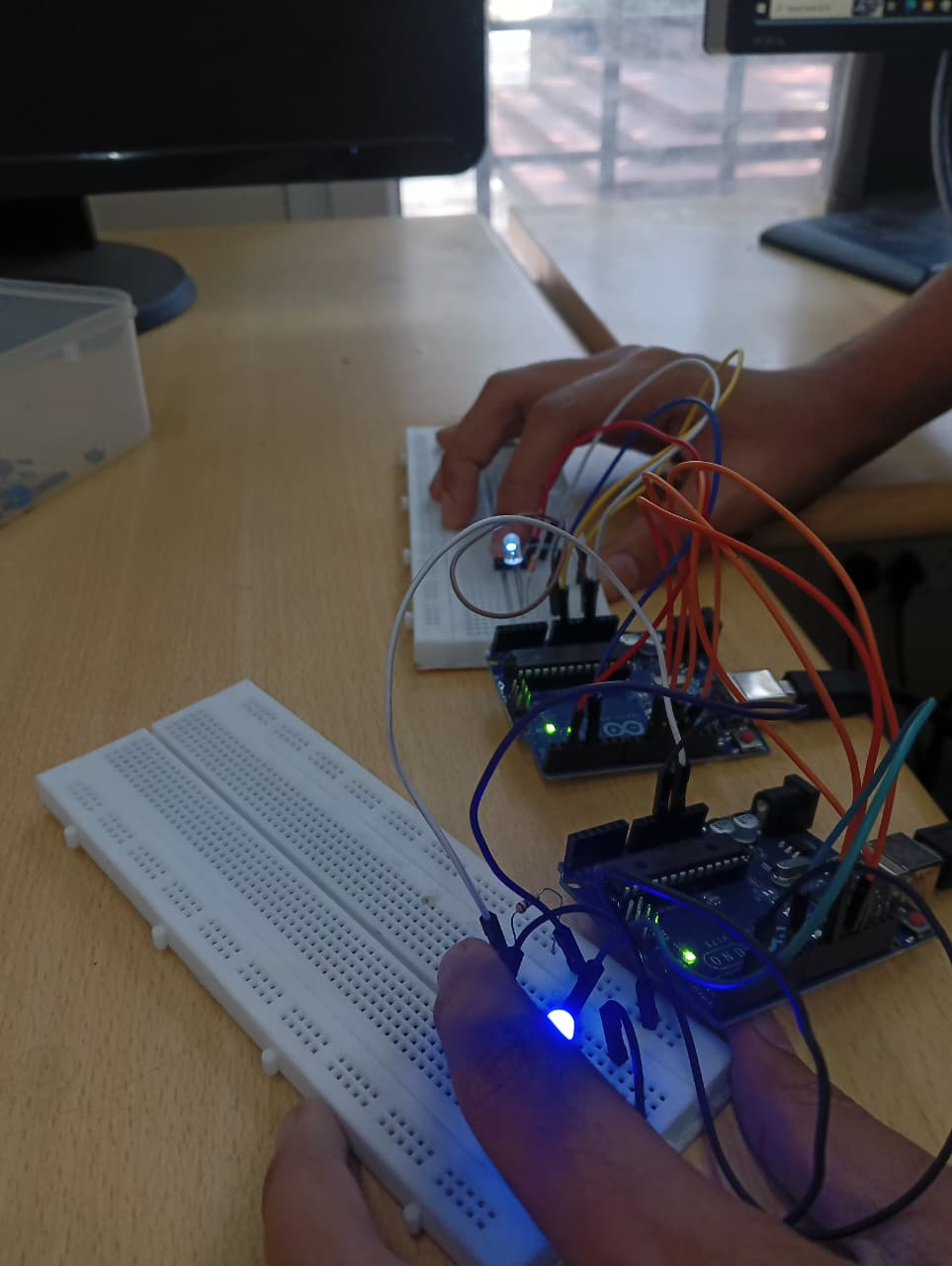
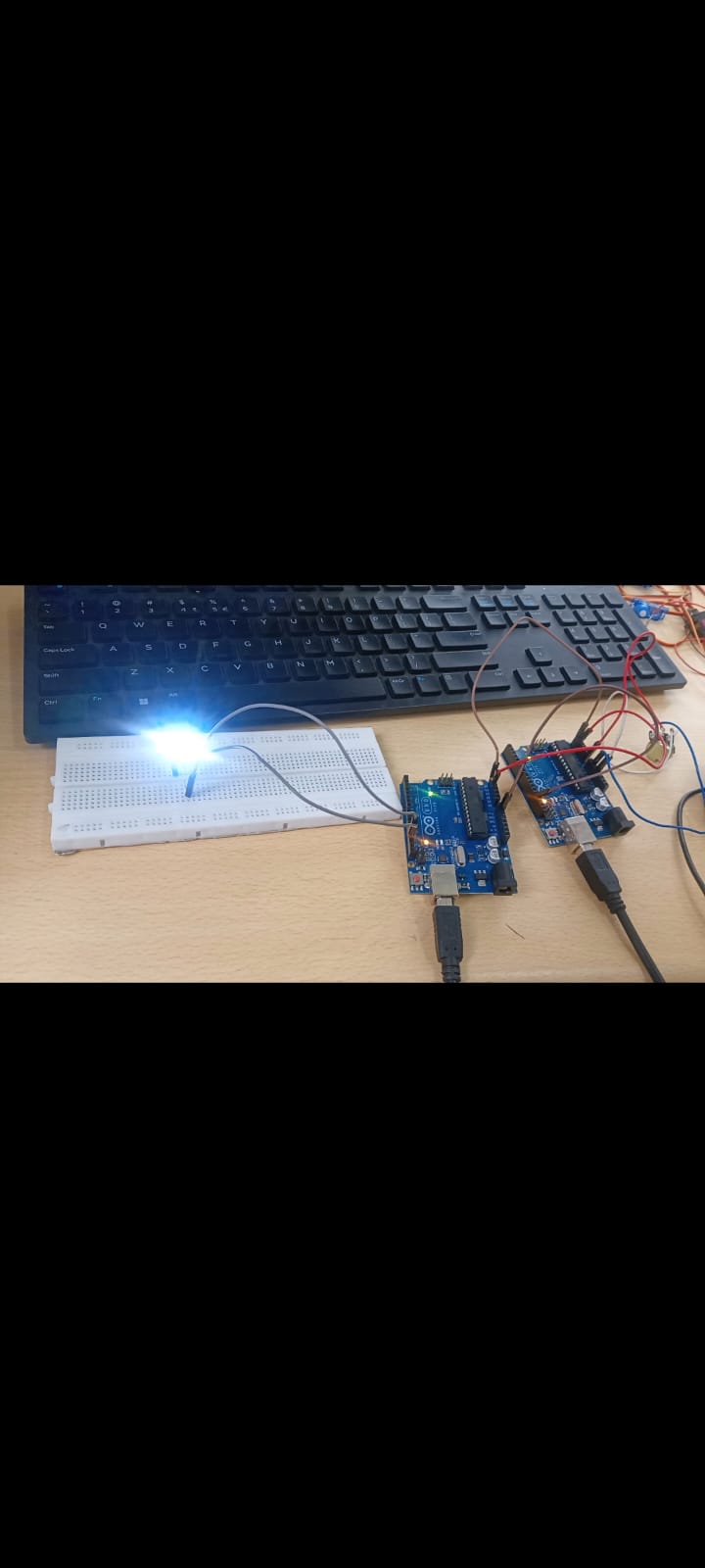
Task 2 : SPI COMMUNICATION
Task Description
This task involves the implementation of SPI communication between two Arduino.
concept:
SPI (Serial Peripheral Interface) is a synchronous serial communication protocol that allows for high-speed, full-duplex (simultaneous send/receive) data transfer between a master device and one or more slave devices over short distances.
Purpose:
SPI (Serial Peripheral Interface) is used because it provides a fast, reliable, and simple way to transfer data between a microcontroller (master) and one or more peripherals (slaves).
MY APPROACH
1. First I learned about the theroy from the resources provided.
2. Second with the help of the circuit diagrams made the connections.
3. Uploaded the code on arduino ide and got the expected outcome.
RESULTS AND OUTCOME
Task 3 - I2C Control
Task description
This task involves the implementation and learning of I2C.
Concept
I2C which stands for Inter-Integrated circuit is a protocol that allows multiple devices to communicate with each other.
The I2C consist of two bus wires:-
SCL (Serial Clock Line): This line carries the clock signal generated by the controller. It dictates the speed and timing of the data transfer, ensuring all devices are synchronized.
SDA (Serial Data Line): This is the line where the actual data is sent and received, bit by bit. Both the controller and the target can transmit data over this line, but only one at a time.
RESULTS AND OUTCOME
Task 6 - Smart Active Battery Balancer
Task Description
Building a battery balancer that transfers excess charge from higher voltage cell to lower voltage cell.
Concept
A battery balancer is used to equalize between voltage across many different battery cells.This is mainly done so that the batteries do not gets overcharged or the charge gets to low. There are two types of actice battery balancer:-
1.Passive Balancer -It dissipates excess charge from higher-charged cells as heat through a resistor or bypass route
2Actice Balancer-An active battery balancer is a device that redistributes energy between cells in a multi-cell battery pack to equalize their voltage levels during both charging and discharging. Unlike passive balancers that waste excess energy as heat, active balancers use power conversion to transfer energy from higher voltage cells to lower voltage cells, improving overall battery performance, efficiency, and lifespan.
How this battery balancer works is that it the arduino uno measure each cells battery voltage using its analog input.
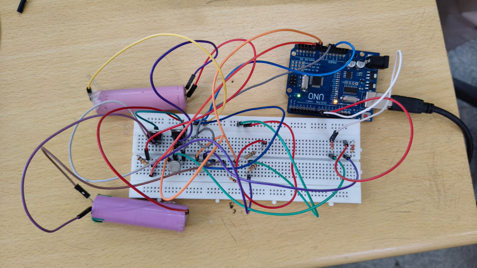
For this task we are going to make a smart active battery balancer using arduino as the microcontroller.
Although the serial monitor showed that the battery is balanced but due to low charge in the Li-ion battery cell the charge could not properly distributed.
The smart active battery balancer uses MOSFET which acts as switch and is responsible to transfer energy from higher energy cell to lower energy cell to maintain balance. Arduino here is responsible to monitor the cell voltage and rapidly switch ON/OFF the MOSFET.
Task 7 - Regenerative Braking System Demo
Task Description
The main objective of this task is to demonstrate regenerative braking using a 9V DC motor connected to a circuit with LED, transistor, and pushbutton. When the motor is stopped via braking, the back EMF lights up the LED, simulating energy recovery in EVs.
CONCEPT
When you accelerate an electric vehicle (EV), the electric motor uses battery power to turn the wheels. Regenerative braking simply reverses this process. When you lift your foot off the accelerator or press the brake pedal, the motor switches into a generator mode. The car's kinetic energy (its momentum) forces the motor to spin, which generates electricity. This generated electricity is fed back into the battery pack to recharge it, effectively recovering energy that would have been lost as heat in traditional friction brakes. This process also creates a braking force, slowing the vehicle down.
.png)
RESULT AND OUTCOME
.jpeg)
Below is the working video of the battery balancer.
Task 8 - Interfacing STM32 Nucleo with L298N Motor Driver
TASK DESCRIPTION
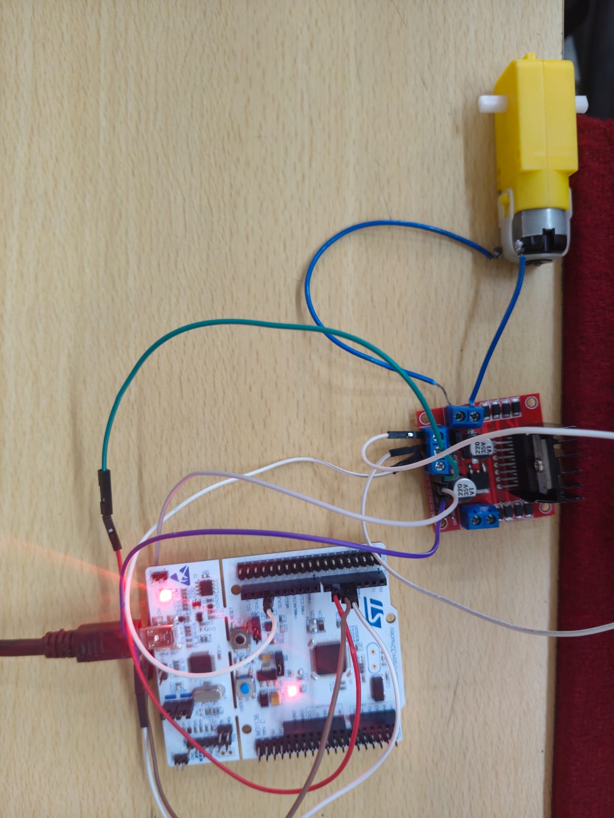
The main objective of this task is to control the speed of DC motor using stm32 and L298N motor.
CONCEPT
The STM32 is a nucleo board which has a ST-LINK already connected with it. Similiar to the task where we used an arduino to control the direction and speed of DC motor, here we will be using an STM32 to give out the signals.
RESULTS AND OUTCOME
Finally learned to use the STM32CUBE IDE and learned about the pinout diagrams to get the resulted output.
Task Description
The main objective of this task is to Use STM32 to control a servo motor by generating PWM signals through internal timers. Adjust pulse width to change the angle of the servo and observe precision motion control.
CONCEPT
An internal timer on an STM32 is like a precise, high-speed stopwatch built into the chip. You configure it to count up to a specific number (the "period") and then automatically restart. This creates a reliable, repeating time interval.
A PWM (Pulse Width Modulation) signal is a digital pulse that repeats at this fixed interval set by the timer (e.g., every 20 milliseconds for a servo). To control the servo, you don't change the interval, but you change the width (duration) of the "on" part of the pulse. The servo reads this pulse width as an angle: a short pulse (like 1ms) tells it to go to one end (0°), a medium pulse (1.5ms) to the center (90°), and a longer pulse (2ms) to the other end (180°).
RESULTS AND OUTCOME
Circuit Connections
.png)
LEARNING
The major learning from this task is learned to read datasheets. After going through the data I got to know the functions of the the small circuit components and I learned how the communication protocols like UART,I2C etc are used. I also learned how the clock configuration in STM32 works.
Task 10 - Configuring ADC in STM32 Nucleo Board
Task Description
To learn how STM32 ADC(Analog to Digital converter works) using a potentiometer or any sensors.
Concept
ADC stands for Analog To Digital Converter. An ADC (Analog-To-Digital) converter is an electronic circuit that takes in an analog voltage as input and converts it into digital data, a value that represents the voltage level in binary code. The ADC samples the analog input whenever you trigger it to start conversion. It performs a process called quantization to decide on the voltage level and its binary code that gets pushed into the output register.
The stm32 we use in our lab is the F446RE model which has three 3 ADC and each ADC has 12 bit.
.png)
RESULT AND OUTCOME
https://youtu.be/deMF2xu_ASQ?si=OuLmHlONNZdAnOmW
I referred to this youtube channel to get the code and setup my CUBEIDE.