
COURSEWORK
Abhi's IOT-001 course work. Lv 2
| Abhi Ravi | AUTHOR | ACTIVE |
31 / 12 / 2024
TASK 1
API:
API (Application Programming Interface ) is a set of rules(actions or operations) and protocols that allows one software application to interact with another. API enables the data exchange and interaction between different software.
How API Works :
1)Client: Sends a request to the API (e.g., "Get weather for London").
2)API Server: Processes the request and fetches data or performs the requested operation.
3)Response: Returns the result (e.g., temperature, humidity).
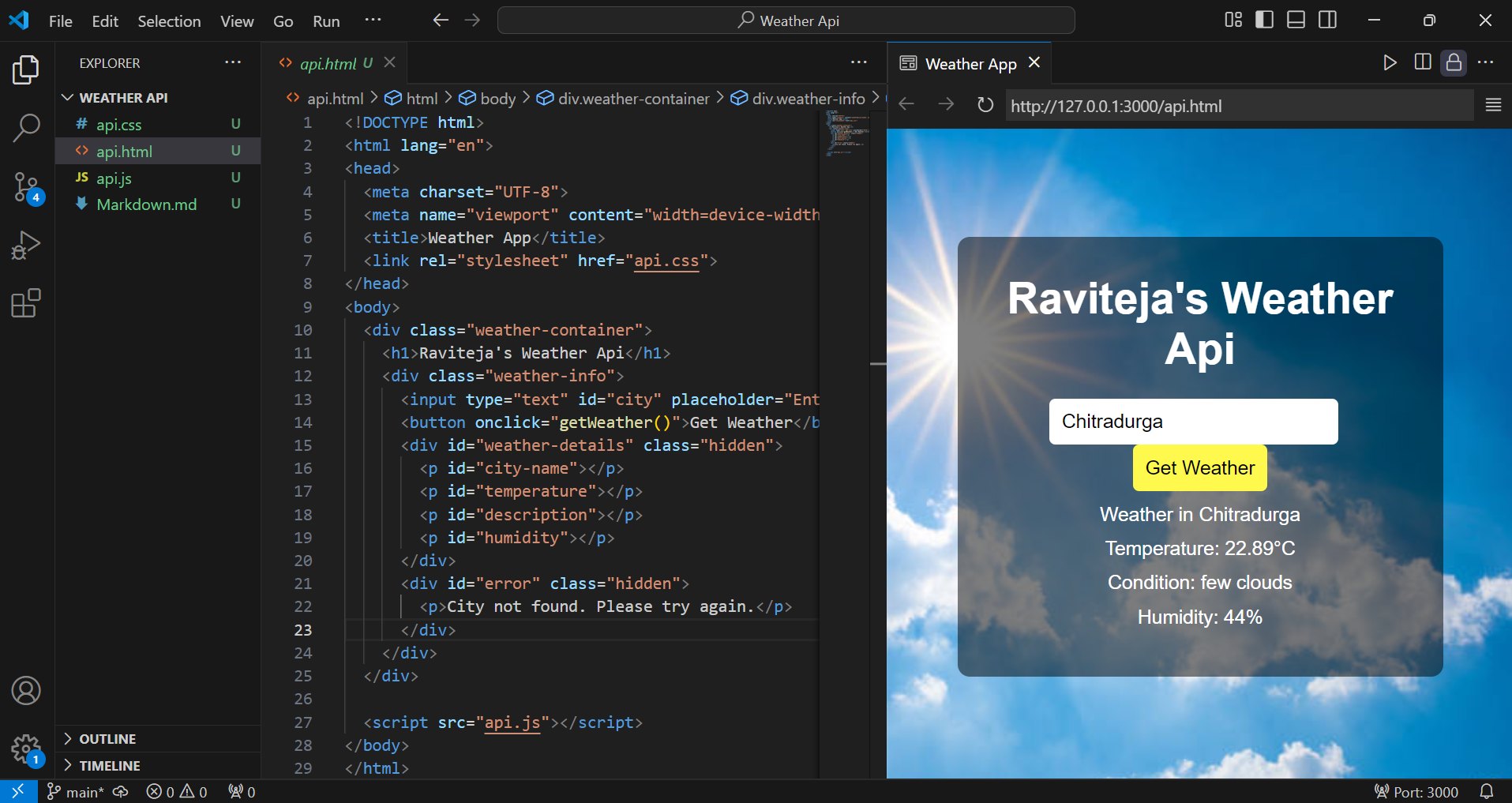
A weather API provides weather related information such as temperature , humidity , wind speed and forecasts.First I went to official website ( https://openweathermap.org/) and created my account to generate API key . And in VSCode I implemented code using languages HTML , CSS and JAVASCRIPT and I linked my API key to fetch the weather forecasts.API
TASK 2
Working with GITHUB :
GitHub is a platform that uses Git (is a version control system) to help coders and developers to manage code , collaborate , and track changes in their projects.
Key Concepts in GitHub :
1)Repository : A storage space for the codes and project files.
2)Branch: A separate line of development that allows multiple people or ideas to coexist independently.
3)Commit: It describes the specific changes made, making it clearer to others and for future reference.
4)Pull Request : A request to merge changes from one branch into another. Facilitates collaboration and code review.
5)Fork: A personal copy of someone else's repository where we can experiment without affecting the original project.
6)Clone: A local copy of a repository usually developers clone repositories to work offline.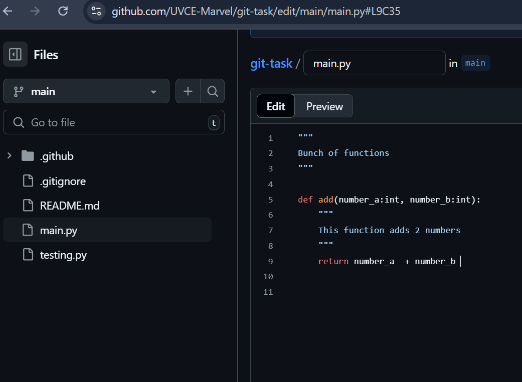
TASK 3
UBUNTU TASK:
Ubuntu is a free and open source operating system in the Linux kernel.It is well-known for its user-friendly interface and stability, making it suitable for beginners and advanced users.
Steps I followed:
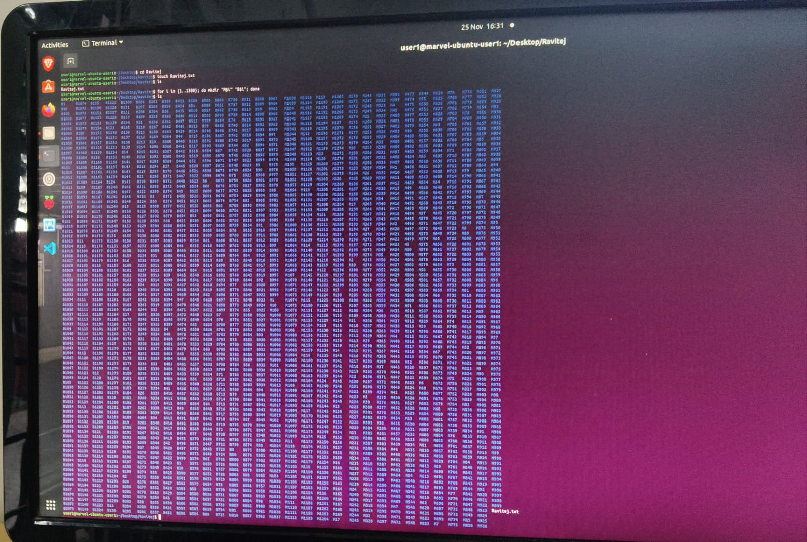
1)Firstly I made a new directory named 'Ravitej' using the mkdir command.
2)Then navigated into to directory 'Ravitej.txt' with the cd command.
3)By using the touch command to create an empty file called blankfile.txt.
4)Then displayed the contents of the folder using the ls command.
5)It generated 2600 directories by running a loop: for i in {1..1300}; do mkdir "M$i" "B$i"; done.
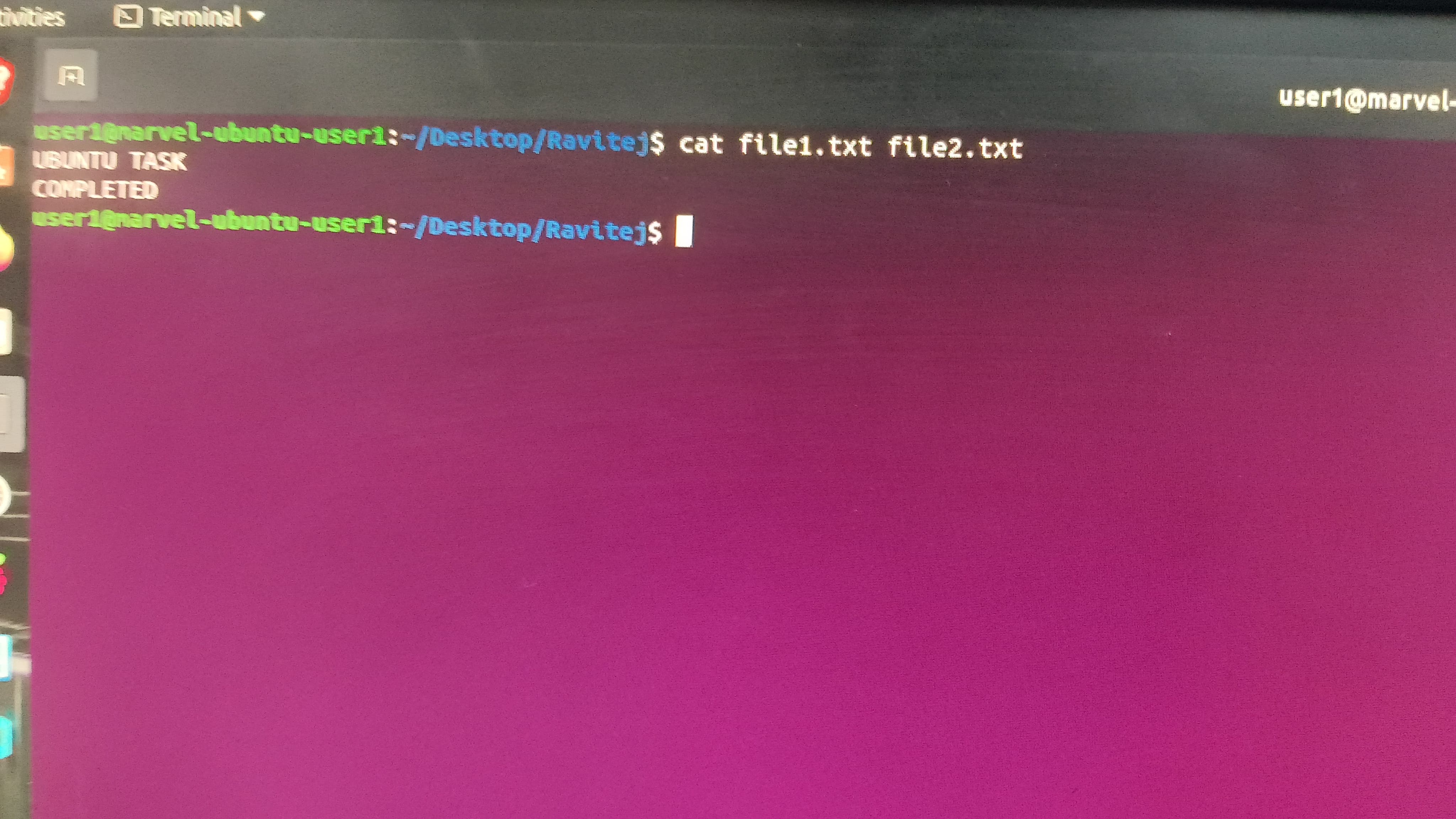
6)I merged the content of two text files, file1.txt and file2.txt, and displayed them on the terminal using the cat command.
Since I gave 'UBUNTU TASK' in text 1 and 'COMPLETED' in text 2 , it gave me the output by concatenating it as 'UBUNTU TASK COMPLETED'.
TASK 4
Working with Pandas and Matplotlib:
Steps to be followed :
1)Imported the required libraries like Pandas and Matplotlib, to work with data and create visualizations.(To complete this step I setup PYTHON along with PIP completely and added to path)
2)Loaded the dataset into a Pandas DataFrame to organize and process the data.
3)Through visualize the data of my 1st semester academic performance.
4)Plotted a line graph , Bar graph and Scatter plot using Matplotlib Created a bar graph by taking variables like number of subjects, hours studied, marks scored, attendance % in each subjects.
6)Customized the graphs by adding titles, labels.
7)Displayed all three visualizations together for comparison and analysis.


TASK 5
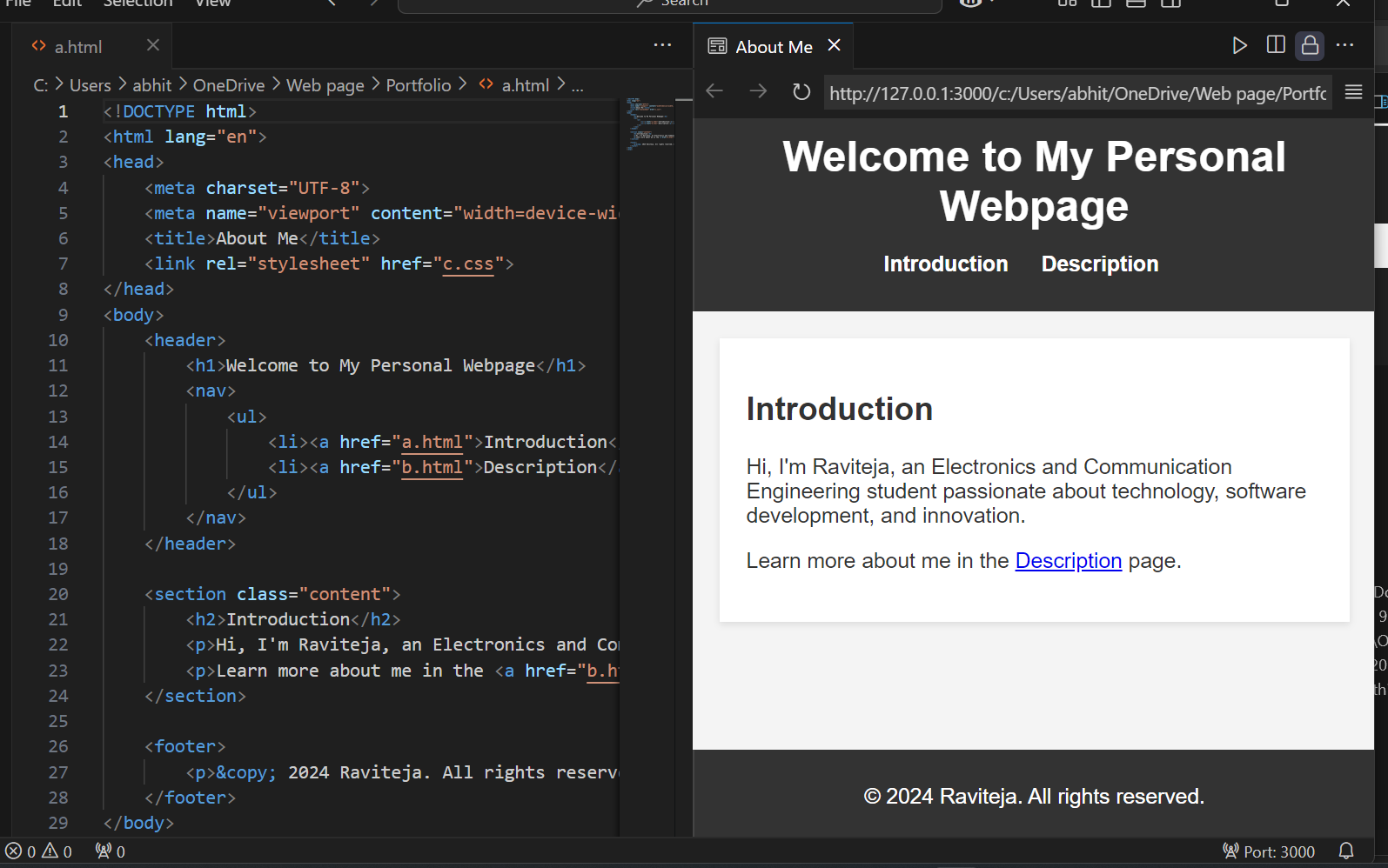
Create a Portfolio Webpage:
1)By designing this portfolio we can present our skills,projects and we can showcase our designing approach and technical proficiency. 2)Website should be responsive and pushed to the git repository. 3)I used HTML and CSS to design the my portfolio page.
TASK 6
Writing Resource Article using Markdown:
Markdown is a lightweight markup language for creating formatted text using a text editor.
Markdown is an easy-to-use markup language that is used with plain text to add formatting elements (headings, bulleted lists, URLs) to plain text without the use of a formal text editor or the use of HTML tags.
TASK 7
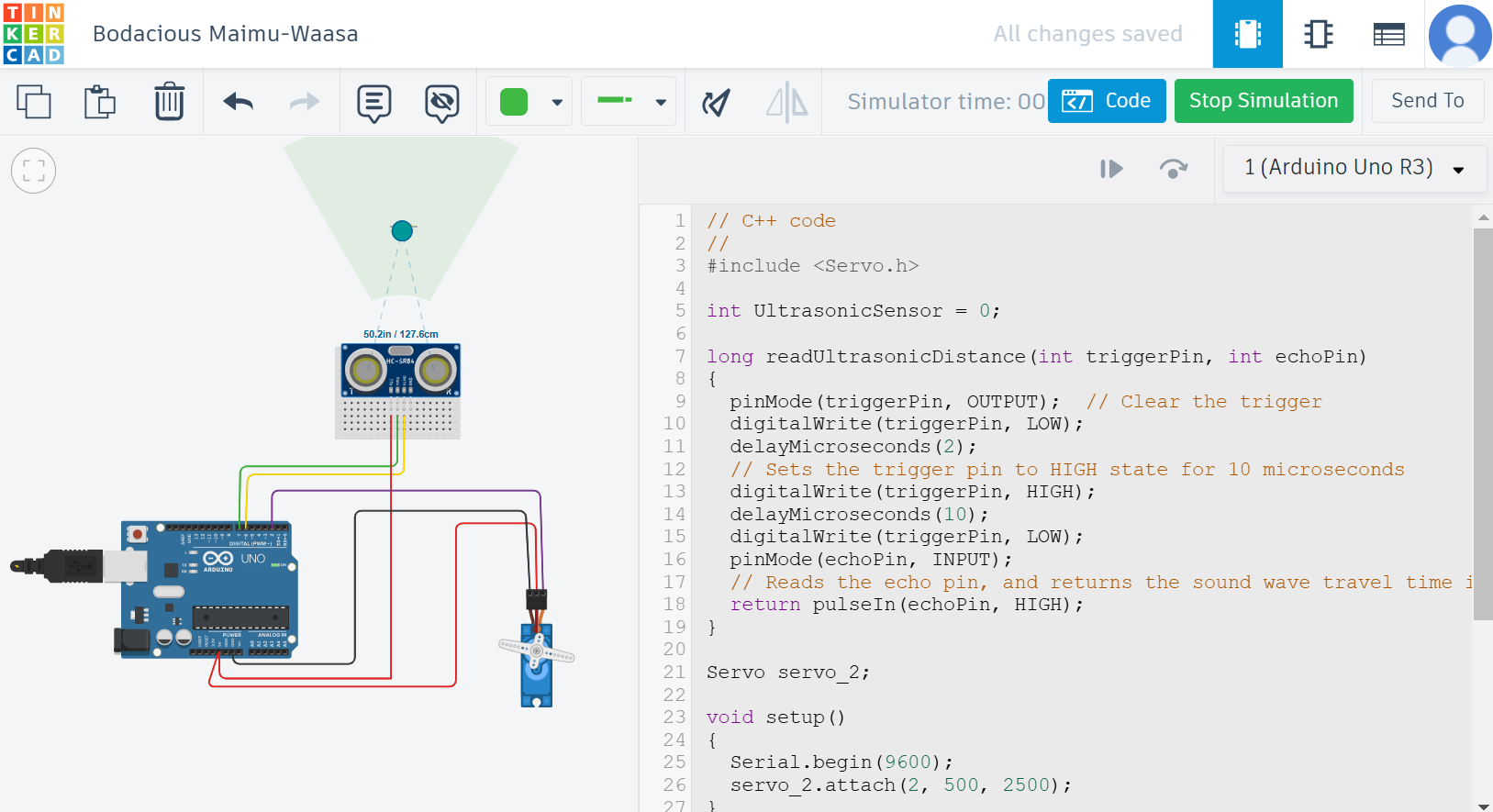
Tinkercad:
To perform this task of an ultrasonic sensor components required are :
1)Ultrasonic Distance Sensor(4 pin).
2)Arduino Uno R3.
3)Micro Servo.
The distance between the ultrasonic sensor and the object is calculated based on the time it takes for the reflected ultrasonic wave to reach the receiver.
The formula used for this calculation is:
𝑑=𝑠⋅𝑡
where:
𝑑 = Distance between the object and the ultrasonic sensor
s = Speed of the ultrasonic wave signal
t = Time taken by the reflected signal to reach the receiver
TASK 8
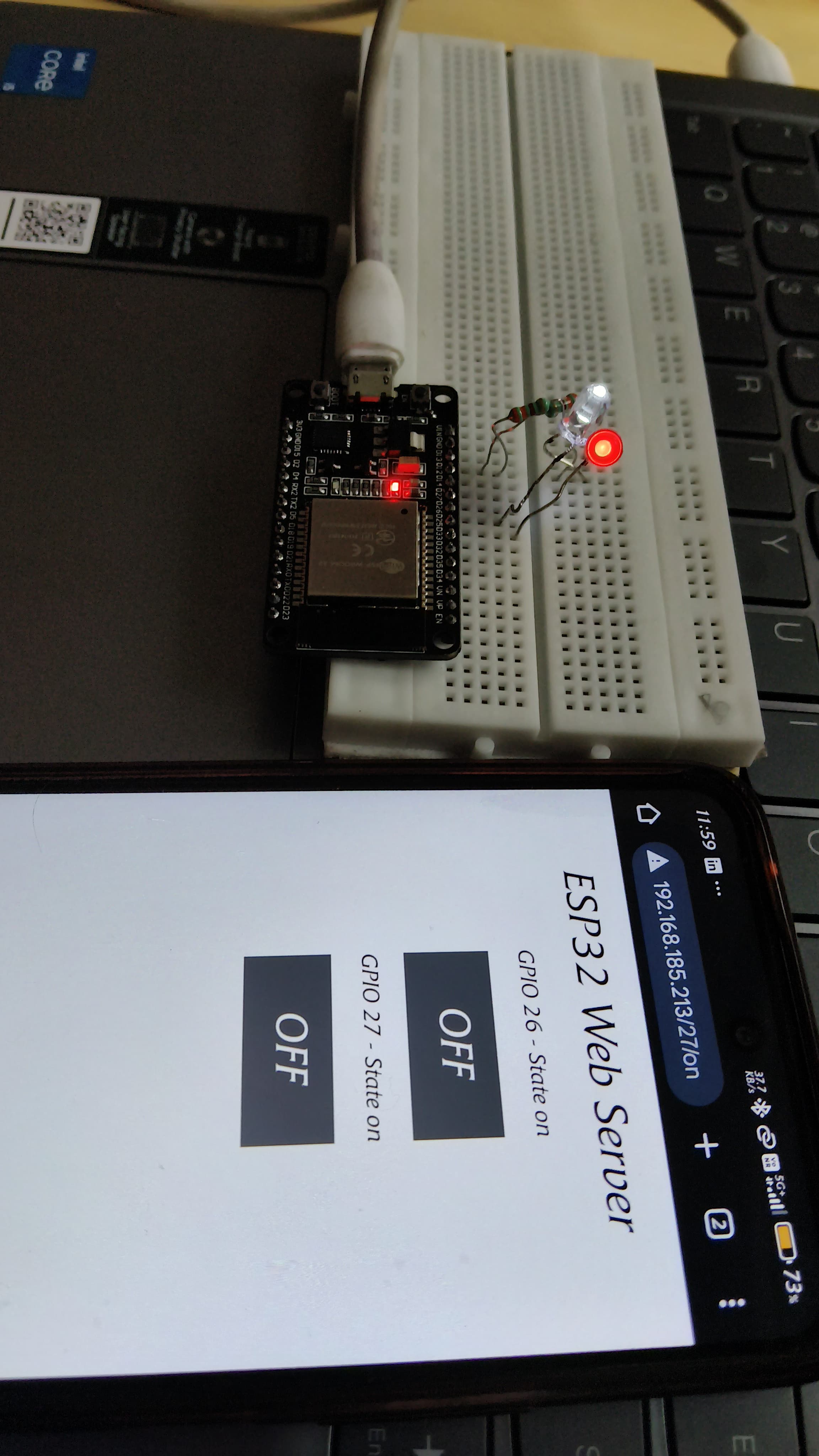
LED Toggle Using ESP32
ESP32 is a microcontroller that supports wireless connectivity.ESP32 is a powerful and versatile with built-in Wi-Fi and Bluetooth capabilities, making it suitable for IoT projects.LEDs can be connected to GPIO pins of the ESP32, and their ON/OFF states can be controlled using digital output by connecting our mobile network(WIFI) using IP address.
Steps I followed:
- I connected the ESP32, the LED lights and the resistors on the breadboard.
2)Next I uploaded the code consisting of my mobile hotspot details to ESP32 using the Arduino IDE. Then, I entered the IP address in my phone that was displayed on the serial monitor.
3)And through my phone's web I controlled the toggling of LEDs' this way.

TASK 9
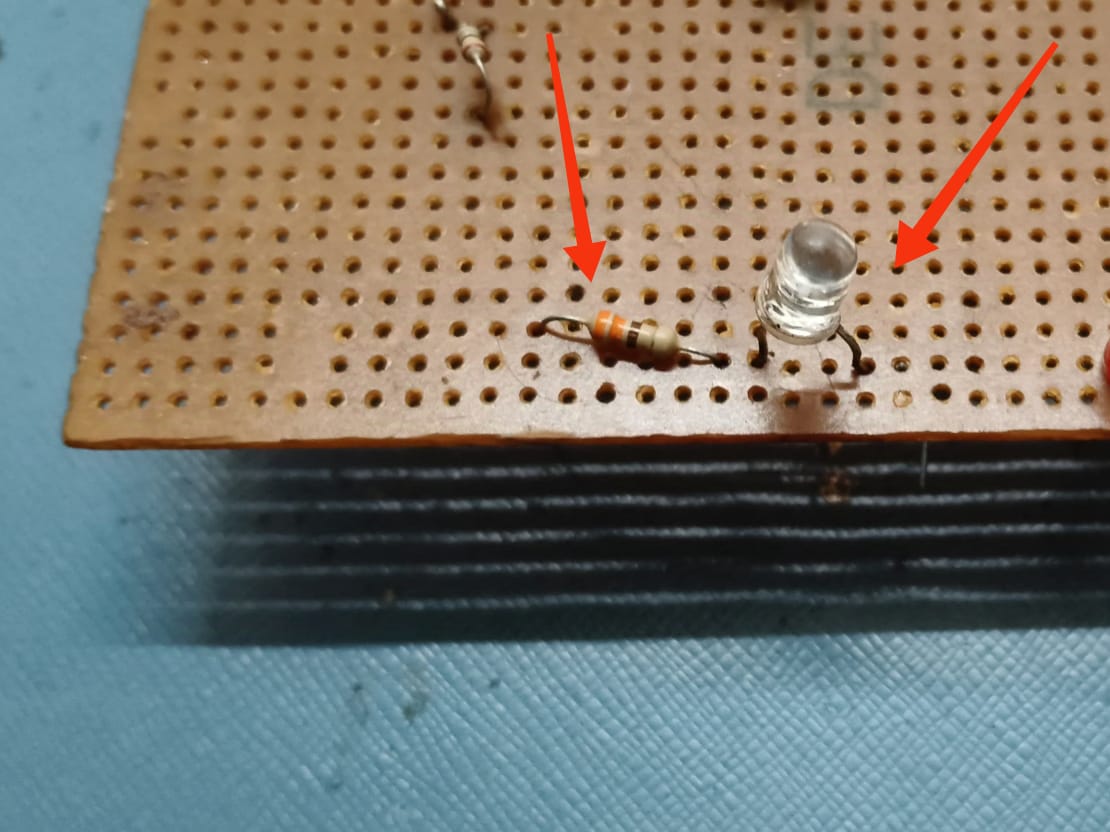
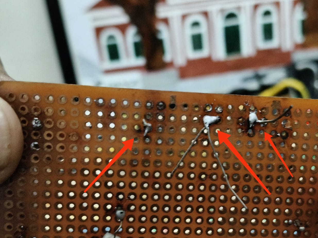
Soldering Prerequisites:
Definition: Soldering is a process of joining electronic components by melting a filler metal(solder) to create a permanent electrical and mechanical connection.
Key Components:
1)Soldering Iron: Tool used to heat the solder.
2)Solder: A metal alloy (tin and lead or lead-free alternatives) that melts to form the connection.
3)Flux: A chemical cleaner to prevent oxidation and ensure a good connection.
Uses:
Prototype Development:
1)Assembling prototypes using sensors, microcontrollers (e.g., Arduino, Raspberry Pi), and modules like Wi-Fi or Bluetooth adapters.
2)Connecting sensors to circuit boards for data collection.
3)Fixing broken connections or upgrading existing equipments and devices.
TASK 10
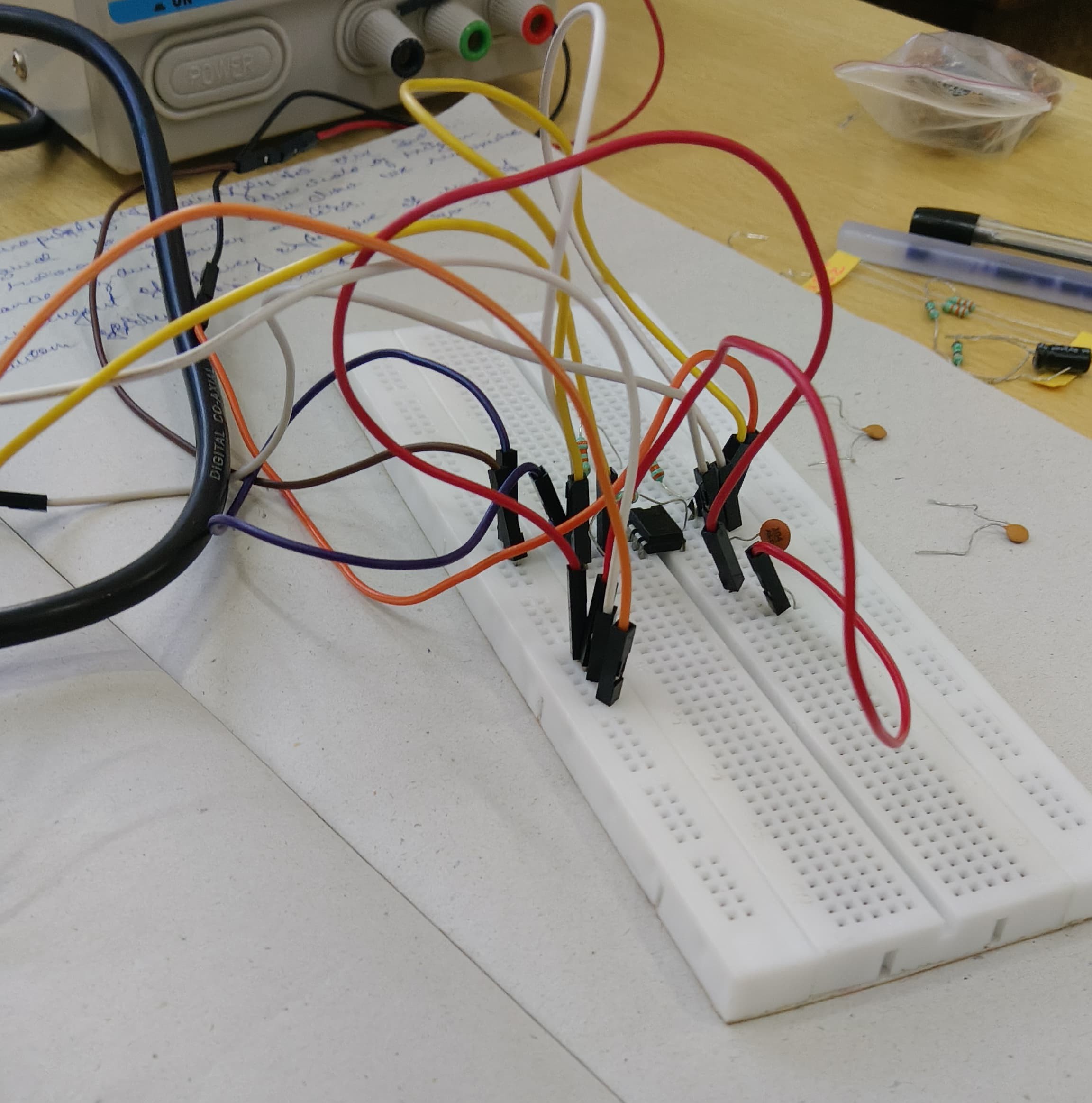
555 Astable Multivibrator
The 555 timer is versatile IC used in various timing , pulse generation , and oscillator applications. In astable mode 555 timer generates continuous square wave output without an external trigger.
In the 555 Oscillator circuit, pin 2 and pin 6 are connected together allowing the circuit to re-trigger itself on each and every cycle allowing it to operate as a free running oscillator. During each cycle capacitor, C charges up through both timing resistors, R1 and R2 but discharges itself only through resistor R2 as the other side of R2 is connected to the discharge terminal (pin 7).
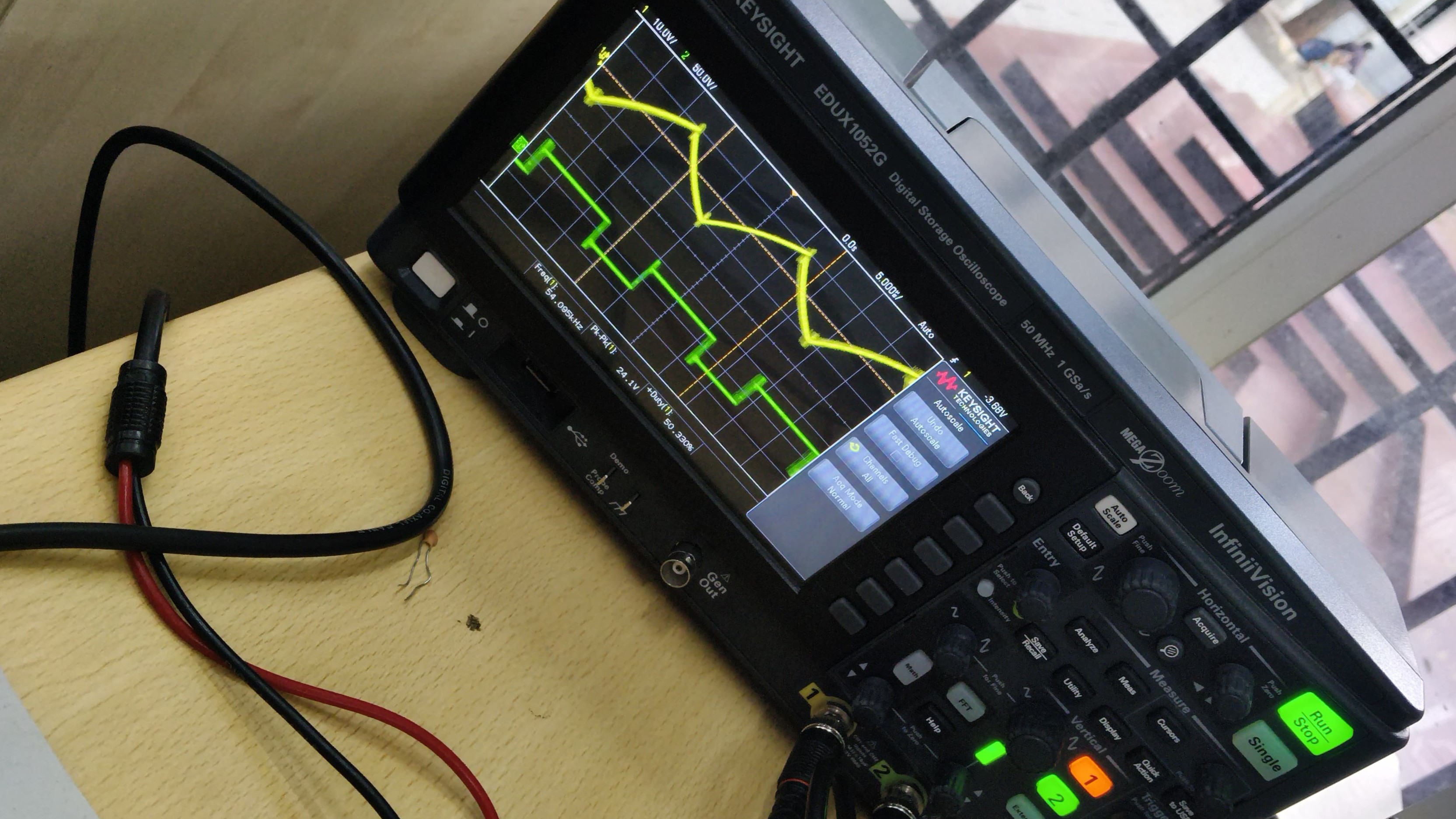
The capacitor charges up to 2/3Vcc (the upper comparator limit) through both resistors R1 and R2 which is determined by the 0.693(R1+R2)C combination. It then discharges itself down to 1/3Vcc (the lower comparator limit) through resistor R2 only which is determined by the 0.693(R2*C) combination.
By altering the time constant of just one of the RC combinations, the Duty Cycle better known as the “Mark-to-Space” ratio of the output waveform can be accurately set and is given as the ratio of resistor R2 to resistor R1. The Duty Cycle for the 555 Oscillator, which is the ratio of the “ON” time divided by the “OFF” time.
We tried multiple times but didn't get the required output and at final got the below output after exchanging the 2 to 3 capacitor.
TASK 11
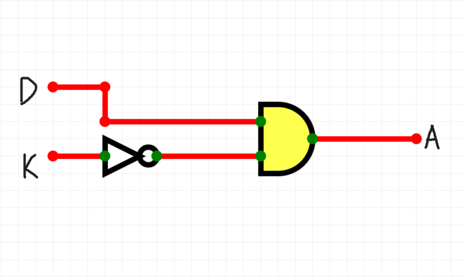
Karnaugh Maps and Deriving the logic circuit:
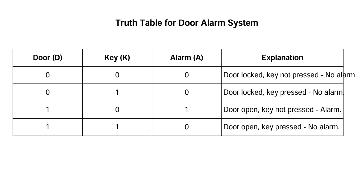
A Karnaugh Map (K Map) is graphical representation used to simplify Boolean algebra expressions. It helps in minimizing logical expressions using simple algebraic techniques.
We have 4 cases based on:
Door: Locked (D = 0) or Open (D = 1).
Key: Not pressed (K = 0) or Pressed (K = 1).
The burglar alarm (output A) should activate(blink a LED or sound a buzzer), it depends the above conditions.
We can draw tabular column by taking conditions.And after getting the outputs for the different conditions we can draw the K map according to the inputs and outputs.
TASK 12
Active Participation:
I have participated in Securathon contest which was organised by IEEE. Where I gain knowledge about powerpoint presentation. And worked to presentation on DDoS Defense in Cloud Architecture
TASK 13
L293D Motor Driver Data Sheet Report
1. Introduction
L293D is a quadruple high-current half-H driver IC used for the driving DC motors and stepper motors. It is designed to provide bidirectional control using an H-bridge configuration , making it as essential component in robotics and automation systems.
2. Features of L293D
-Dual H-Bridge motor driver IC
-Operates at 4.5V to 36V
-Maximum current output: 600mA per channel
-Peak current output: 1.2A per channel
-Enable pins for speed control using PWM
-Thermal shutdown protection
-Used in robotics, motor control circuits, and automation
3. ICs Used in L293D
L293D is built using Darlington transistors and Schottky diodes to provide efficient switching and protection. It consists of:
-Four Darlington Transistor Pairs: Used for high-current amplification.
-Internal Flyback Diodes: To protect against voltage spikes from inductive loads (motors).
-Control Logic Gates: To process input signals and control motor direction.
-Power Supply Pins: Separate logic supply (Vcc1) and motor supply (Vcc2).
4. Working of L293D
L293D operates as a bidirectional motor driver using H-bridge circuits. Each channel has an independent H-bridge, allowing for control of two DC motors or one stepper motor.
H-Bridge Configuration
An H-bridge is a circuit that allows a motor to rotate in both directions by controlling the flow of current. It consists of four transistors:
1)Turning ON diagonally opposite transistors moves the motor in one direction.
2)Switching ON the other diagonal pair reverses the direction.
3)Turning OFF both sides stops the motor.
5. Pulse Width Modulation (PWM) for Speed Control
PWM is used to control the speed of the motor by adjusting the duty cycle of the signal applied to the enable pins (EN1, EN2).
Higher Duty Cycle = More power = Faster speed
Lower Duty Cycle = Less power = Slower speed
PWM Speed Control Example
100% Duty Cycle (Full ON) → Motor runs at full speed.
50% Duty Cycle → Motor runs at half speed.
0% Duty Cycle (Full OFF) → Motor stops.
PWM signals are generated using microcontrollers like Arduino, ESP32, or Raspberry Pi, and applied to the enable pins (EN1, EN2) of L293D.
6. Pin Configuration of L293D
Pin Number - Name and Description
1 - EN1 Enables Motor A (PWM Input)
2 - IN1 Motor A Control Input 1
3 - OUT1 Motor A Output 1
4,5 - GND Ground Pins
6 - OUT2 Motor A Output 2
7 - IN2 Motor A Control Input 2
8 - VCC2 Motor Power Supply (4.5V – 36V)
9 - EN2 Enables Motor B (PWM Input)
10 - IN3 Motor B Control Input 1
11 - OUT3 Motor B Output 1
12,13 - GND Ground Pins
14 - OUT4 Motor B Output 2
15 - IN4 Motor B Control Input 2
16 - VCC1 Logic Power Supply (5V)
7. Applications of L293D
-Robotics (Controlling DC motors in robotic cars)
-Automation systems (Conveyor belts, smart home systems)
-Stepper motor control
-Arduino-based projects
-Remote-controlled vehicles
8. Conclusion
L293D is a versatile motor driver IC capable of driving two DC motors or one stepper motor. With its H-bridge configuration, it provides bidirectional control, and with PWM support, it allows for speed control. Due to its low cost and efficiency, it is widely used in robotics, automation, and embedded systems.
References
-L293D Datasheet (Texas Instruments/STMicroelectronics).
-Arduino and Motor Driver Tutorials.