
29 / 3 / 2025
LEVEL 3 TASKS
🚀 TASK 1 : SPEED CONTROL OF BLDC MOTOR
📌Components required :
- BLDC motor
- Arduino UNO
- Potentiometer
- VRPS
- Electronic speed controller (ESC 30A)
- Bread board and few jumper wires
⚙️WORKING PRINCIPLE OF BLDC MOTOR
A Brushless DC (BLDC) motor works on the principle of electromagnetic induction, using a controller to switch the flow of current to the motor windings.
🔹 Key Components Inside a BLDC Motor:
- Stator – Stationary part containing the windings.
- Rotor – Rotating part equipped with permanent magnets.
- Controller – The electronic circuit that controls current switching.
🔹Applications of BLDC Motor :
- Electric Vehicles: BLDC motors are used in many electric vehicles.
- Industrial Automation: Used in robotics, CNC machines, and other industrial applications.
- Aerospace: Used in aircraft and spacecraft due to their high reliability and efficiency.
📷 BLDC Motor Setup :
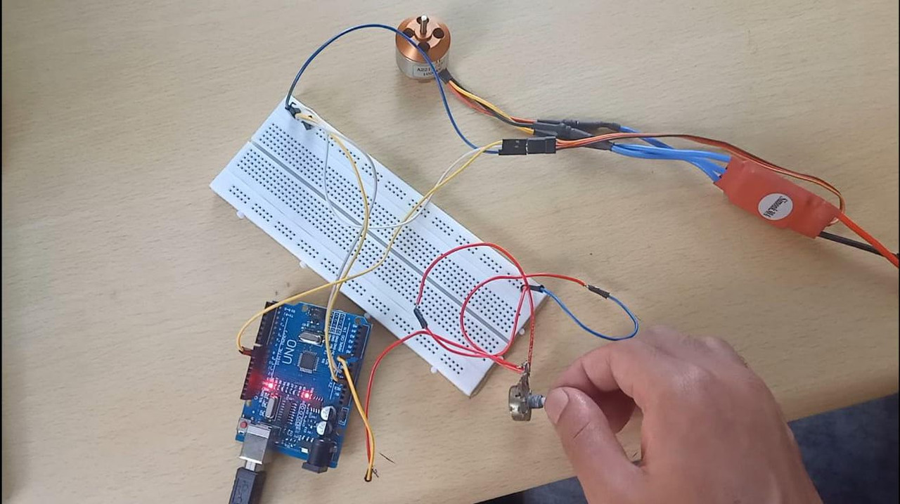
1.Here,potentiometer adjusts the speed of the BLDC motor.
2.BLDC motor is connected to Arduino UNO via Electronic switch controller (ESC 30A) for smooth operation.
🔹Applications of ESC(30A)
- High current handling (up to 30A)
- Smooth acceleration & deceleration
- Efficient power management
- Compact design
🔄 TASK 2 : SPI COMMUNICATION
📌Components Required :
- Arduino UNO
- Bread board
- Jumper wires
💡Key Takeaways
🔹SPI (Serial Peripheral Interface) is a fast and synchronous communication protocol used for short-distance data transfer between microcontrollers and peripheral devices like sensors, SD cards, displays, and motor controllers.
🔹Arduino supports SPI communication using the SPI library.
🛠SPI uses four main signals:
- MOSI (Master Out Slave In) → Data sent from the master to the slave.
- MISO (Master In Slave Out) → Data sent from the slave to the master.
- SCK (Serial Clock) → Clock signal generated by the master.
- SS (Slave Select) → Selects the slave device (active LOW).
📷 SPI Communication Setup:


🔬 Understood how SPI communication works using Arduino
🔗TASK 3 : I2C PROTOCOL
📌Components Required :
- Arduino UNO
- Bread board
- Jumper wires
💡Key Takeaways
🔹I²C (Inter-Integrated Circuit) is a two-wire communication protocol used to connect multiple devices like sensors, displays, EEPROMs, and RTC modules with minimal wiring.
🔹I2C uses only two lines for communication:
- SDA (Serial Data Line) → Transmits data between devices.
- SCL (Serial Clock Line) → Provides the clock signal from the master.
🔹I2C supports multiple masters and multiple slaves on the same bus, using unique 7-bit or 10-bit addresses to identify devices.
📷 I2C Communication Setup:

🔬 Understood how I2C communication works using Arduino Uno
🔋TASK 4&5 : LITHIUM-ION BATTERY PACK AND BMS
🔹 Connected three lithium ion cells (each 3.7volts 2000mAH) in series combination to increase voltage and in parallel combination to increase current, connecting cells in series& parallel combination improves overall capacity and efficiency of battery.
⚡IMPORTANCE OF BMS
🔹BMS stands for Battery Management System
- Protection Against Overcharging & Over-Discharging
- Cell Balancing for Longer Battery Life
- Overcurrent and Short-Circuit Protection
- Temperature Monitoring and Thermal Management
⚡Applications of BMS
- Electric Vehicles (EVs) & E-Bikes → Protects high-voltage battery packs.
- Renewable Energy Storage → Ensures long life in solar & wind storage systems.
- Drones & Robotics → Prevents damage from rapid charge/discharge cycles.
- Medical Devices → Critical for backup power safety in hospitals.
🔋Battery Pack :

🚗TASK 6 - BUILD CHASIS
🔹Designed an RC car chassis using TINKERCAD software
MARVEL ELECTRIC 🚙


⚙️Task 7 - WORKING WITH MULTIPLE SENSORS
🚗OBJECT AVOIDING VEHICLE
📌Components Required :
- RC Car Chassis
- Arduino UNO
- L298N Motor driver
- Ultra sonic sensor
- DC Motors (4 no's)
- Jumper wires
- Bread board
💡APPROACH
🔹Attached four DC Motors to chassis, and connected motors to Arduino via L298N motor drivers for smooth operation and control.
🔹Attached a servo motor to chassis and connected it to Arduino directly to control servo motor using PWM (pulse width modulation).
🔹Configured ultrasonic sensor to Arduino to detect objects.
🔹Connected my lithium battery to motor drivers ensuring that all ground connections are connected to common ground (to complete circuit).
🔹programmed Arduino to receive signals from ultrasonic sensors and control dc motors (fully automatic)
🚗 PROTOTYPE
