
Asshray's Ev-Re Level 3 Report
29 / 3 / 2025
Task 1- Build Chassis
Objective:
Use any software of your comfort to design a complete chassis of an RC car with dimensions compatible to be printed on the 3D printer available in MARVEL. The chassis should be have a calculated weight distribution depending on the application.
Chassis Designed:
I made the below chassis using Fusion 360 software. First image shows the dimensions of the chassis, and second image shows different views of the chassis.
The thickness of the chassis is 10mm
IMAGE 1:

IMAGE 2:

References:
- Chat GPT for procedure of making the chassis
Task 2- SPI Communication
Objective:
- Understand the working of SPI Communication.
- Demonstrate SPI Communication using 2 Arduinos.
Pre-requisites I learned:
SPI stands for Serial Peripheral Interface
Serial Vs Parallel Communication: Data being transmitted here is 01000011 in binary it is the ASCII code for the letter C
Serial Communication:
![]()
Parallel Communication:
![]()
Full Duplex Communication: Both Receiving and transmitting of data can happen simultaneously between the master & the slave. Half Duplex Communication: Either Receiving or transmitting of data can happen at a time, (between master & slave), both can't happen at the same time.
In SPI you can have only one master and multiple slaves
Major Learning:
For microcontrollers to communicate with sensors we have communication protocols, just like how humans communicate with the help of same language, there are 3 basic types of communication protocols SPI, I2C & UART. These are slower than protocols like USB, ethernet, Bluetooth, and WiFi but are less complicated and enough for IoT projects.
SPI is commonly used in SD card reader modules, RFID card reader modules etc.
Devices communicating via SPI are in a master-slave relationship. The master is the controlling device (usually a microcontroller), while the slave (usually a sensor) takes instruction from the master. SPI supports both half & full duplex communication.
Simplest Master-Slave configuration,
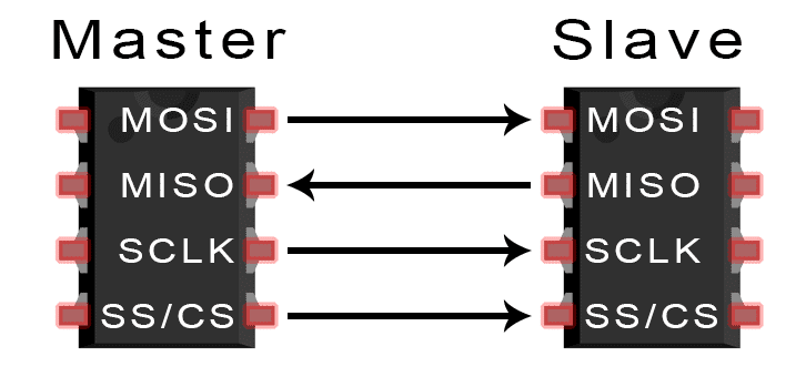
MOSI (Master Output/Slave Input) – Line for the master to send data to the slave. MISO (Master Input/Slave Output) – Line for the slave to send data to the master. SCLK (Clock) – Line for the clock signal. SS (Slave Select) – Line for the master to select which slave to send data to.
Note: 1' Theoretically you can connected infinite slaves to a single master but, in practice, the number of slaves is limited by the load capacitance of the system, which reduces the ability of the master to accurately switch between voltage levels. 2' Data sent from the master to the slave is usually sent with the most significant bit first. 3' The data sent from the slave back to the master is usually sent with the least significant bit first.
In SPI, one bit of data is transferred in each clock cycle, so the speed of data transfer is determined by the frequency of the clock signal.
| SPI | Characteristics |
|---|---|
| Wires used | 4 |
| Max Speed | 10 mbps |
| Clock type | Synchronous |
| Type | Serial |
| Max # of Master | 1 |
| Max # of Slave | Unlimited |
Clock:

- CPOL Determined by, Idle low/high.
- If data read/write happens in first rising/falling edge then phase is 0, therefore CPHA=0
- If data read/write happens after 180° phase of clock i.e., second rising/falling edge then phase is 1, therefore CPHA=1.
- Based on the values of CPOL & CPHA there are 4 modes.
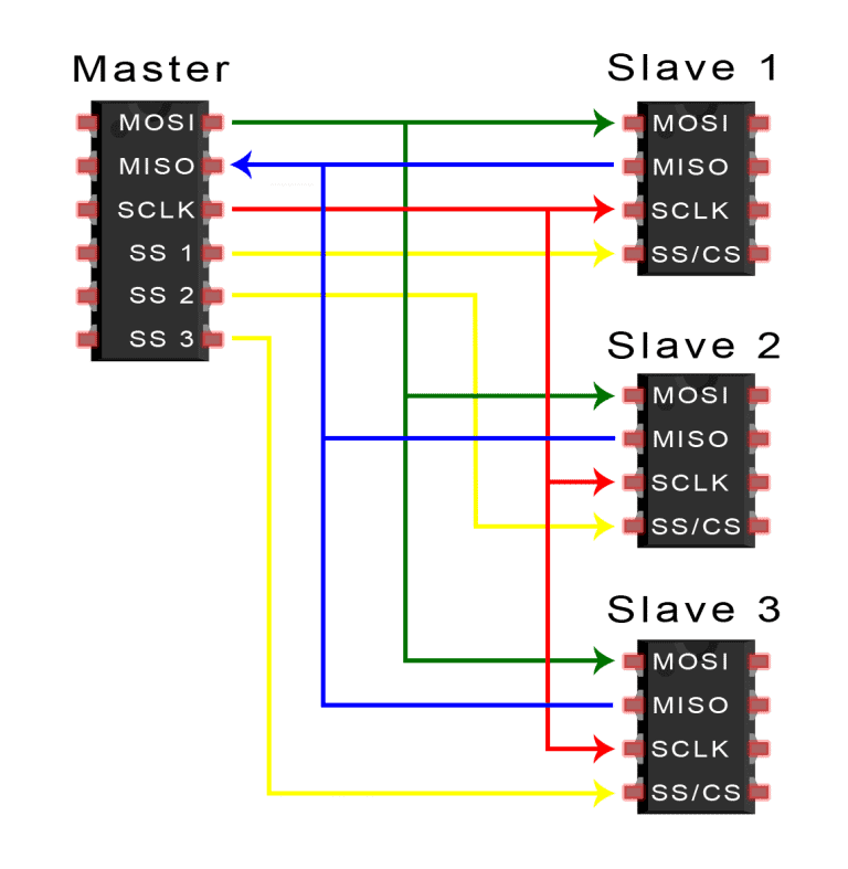
Multiple Slaves:
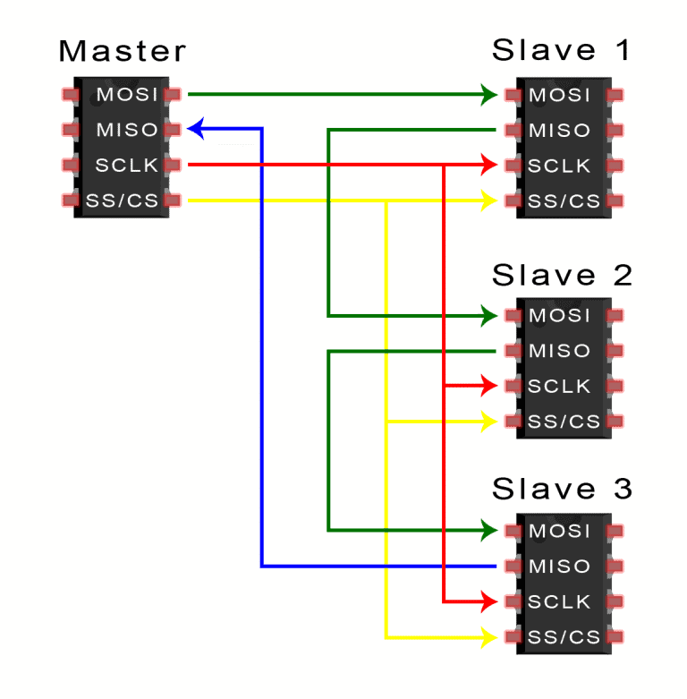 If only one slave select pin is available, the slaves can be daisy-chained like this
Steps of SPI Data Transmission:

Circuit Diagram:
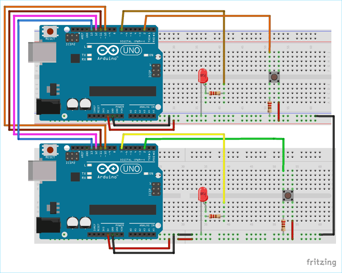
Actual Diagram:
 Here I used Potentiometer instead of push buttons
References:
- Click here: Understand SPI Communication
- Click here: Understand SPI Communication YT
- Click here: Task
- Click here: YT Ref for the task
Task 3- I2C Control
Objective:
Establish a I2C communication between 2 Arduinos.
Pre-requisites I learned:
I2C stands for Inter Integrated Circuits. I2C has only two wires while SPI uses four and I2C can have multiple masters, while SPI can have only one master . So, if there are more than one microcontroller in a project that need to be masters then I2C is used. I2C communication is generally used to communicate with Gyroscope, accelerometer, barometric pressure sensors, LED displays etc.
Major Learning:
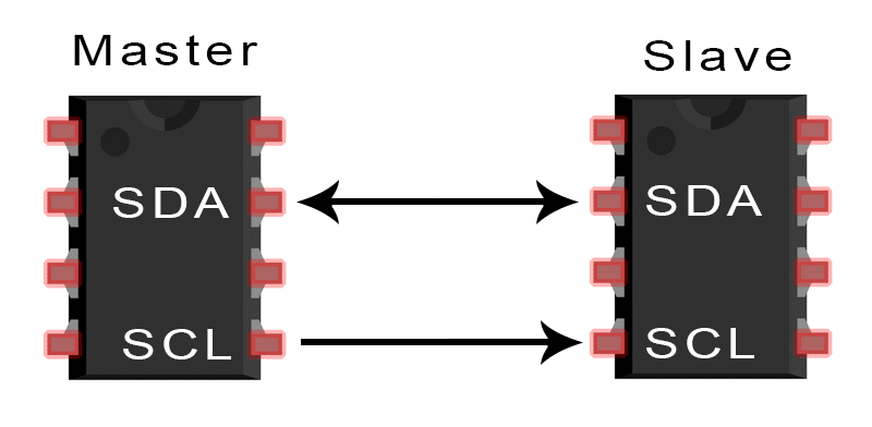 SDA (Serial Data) – The line for the master and slave to send and receive data.
SCL (Serial Clock) – The line that carries the clock signal.
SDA (Serial Data) – The line for the master and slave to send and receive data.
SCL (Serial Clock) – The line that carries the clock signal.
Characteristics of I2C communication are as follows:
| I2C | Characteristics |
|---|---|
| Wires Used | 2 |
| Maximum Speed | Standard Mode: 100 kbps |
| Fast Mode: 400 kbps | |
| High speed Mode: 3.4 Mbps | |
| Ultra fast Mode: 5 Mbps | |
| Clock Type | Synchronous |
| Type | Serial |
| Max # of Masters | Unlimited |
| Max # of Slaves | 127 |
| I2C transfers data in messages, which are split into frames. Each message has a slave address, data frames, start/stop conditions, read/write bits, and ACK/NACK signals. | |
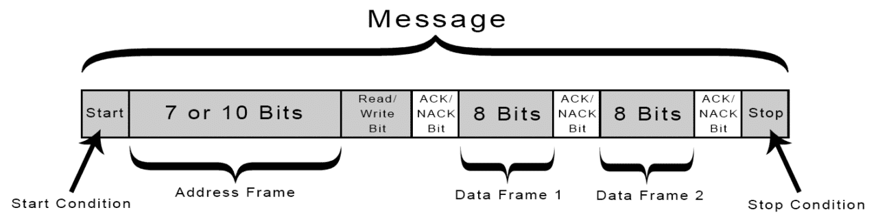 | |
| Start Condition: The SDA line switches from a high voltage level to a low voltage level before the SCL line switches from high to low. | |
| Stop Condition: The SDA line switches from a low voltage level to a high voltage level after the SCL line switches from low to high. | |
| Address Frame: A 7 or 10 bit sequence unique to each slave that identifies the slave when the master wants to talk to it. | |
| Read/Write Bit: A single bit specifying whether the master is sending data to the slave (0) or requesting data from it (1). | |
| ACK/NACK Bit: Each frame in a message is followed by an acknowledge/no-acknowledge bit. If an address frame or data frame was successfully received, an ACK bit is returned to the sender from the receiving device. |
The Data Frame:
After the master detects the ACK bit from the slave, the first data frame is ready to be sent.
The data frame is always 8 bits long, and sent with the most significant bit first. Each data frame is immediately followed by an ACK/NACK bit to verify that the frame has been received successfully. The ACK bit must be received by either the master or the slave (depending on who is sending the data) before the next data frame can be sent.
After all of the data frames have been sent, the master can send a stop condition to the slave to halt the transmission. The stop condition is a voltage transition from low to high on the SDA line after a low to high transition on the SCL line, with the SCL line remaining high.
Steps of I2C Data Transmission:

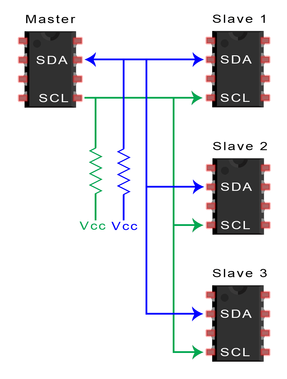
- Single Master with Multiple Slaves:
- To connect multiple slaves to a single master, wire them like this, with 4.7K Ohm pull-up resistors connecting the SDA and SCL lines to Vcc:
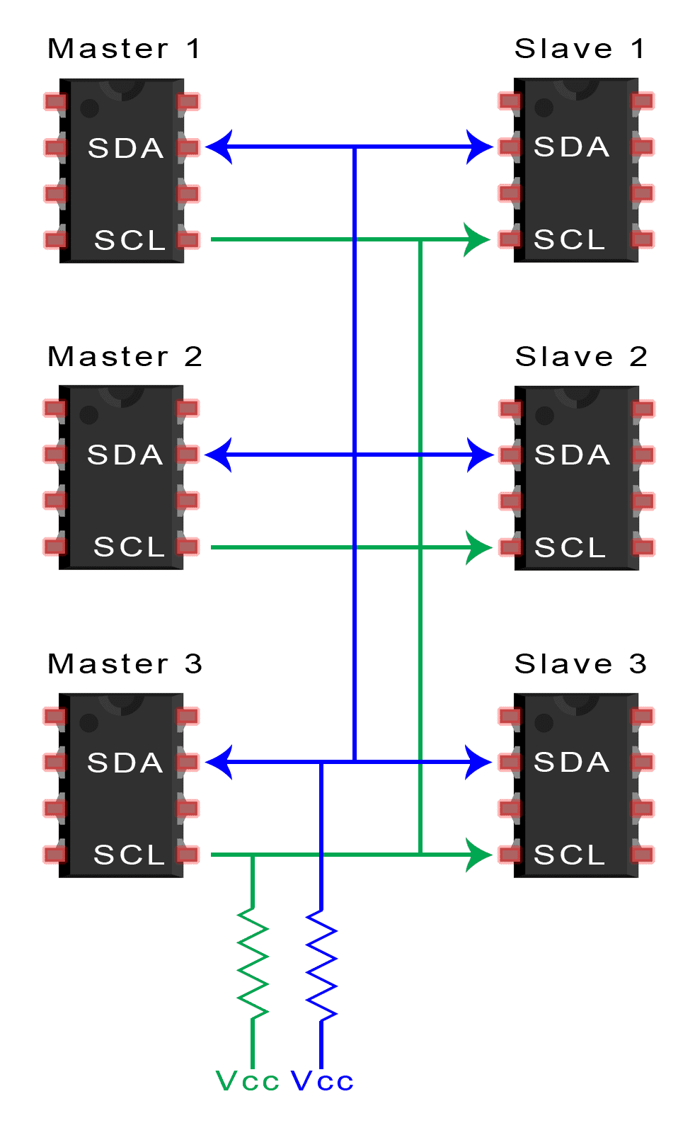
- Multiple Masters with Multiple Slaves:
- The problem with multiple masters in the same system comes when two masters try to send or receive data at the same time over the SDA line, to solve this problem, each master needs to detect if the SDA line is low or high before transmitting a message. If SDA is low, another master is using the bus and should wait till transmission to end; if SDA is high, transmission is safe.
- To connect multiple masters to multiple slaves, use the following diagram, with 4.7K Ohm pull-up resistors connecting the SDA and SCL lines to Vcc:
Circuit Diagram:

Actual Diagram:
References:
- Click here: About I2C
- Click here: Code
Task 5- Speed Control of BLDC
Objective:
- Control the speed of the BLDC motor with the help of a ESC & an Arduino.
Pre-requisites:
The motor we are using is a BLDC motor A2212/13T 1000 KV, i.e., 22 mm is the motor diameter, 12 mm is the rotor height, 13 is the number of wire turns, and it gives 1000 RPM/volt.
There are two types of BLDC motors, outrunner & in runner. Outrunner motors have high torque and In runner motors have high RPM.
Major Learning:
when a potentiometer is connected to an analog pin of a microcontroller (like Arduino or ESP32), it acts as a variable voltage divider. The ADC (Analog-to-Digital Converter) reads this voltage and converts it into a digital value between 0 and 1023 (for a 10-bit ADC). Now, The ADC value (0–1023) can be mapped to a PWM signal. This PWM signal is sent to an ESC to control speed.
-
Arming of ESC & its importance: When initially powering the motor, the signal value must be the same or lower than the minimum value of 1 millisecond. This is called arming of the ESC, and the motor makes a confirmation beeps so that we know that it’s properly armed. In case we have higher value when powering, which means we have a throttle up, the ESC won’t start the motor until we throttle down to the correct minimum value. This is very convenient in terms of safety, because the motor won’t start in case we have a throttle up when powering.
-
ESC Calibration: Every ESC has its own high and low points, and they might slightly vary. For example, the low point might be 1.2 milliseconds and the high point might be 1.9 milliseconds. In such a case, our throttle won’t do anything until it reaches that low point value of 1.2 milliseconds. To solve this issue, we can calibrate the ESC or set the high and low points as we want,
1. **Start with the throttle at maximum (high point)**

    - Before powering the ESC, set the throttle (potentiometer or transmitter stick) to **maximum**

    - This tells the ESC: **“This is the new maximum throttle”**.

    - Now, power on the ESC.

    - You will hear **beeps from the motor**, confirming it detected the new high point.

2. **Set the throttle to minimum (low point)**

    - **Wait for about 2 seconds** after the beeps.

    - Move the throttle to **minimum** (where you want the motor to stop).

    - The ESC will register this as **the new low point**.

    - Another set of beeps will confirm calibration is complete.

3. **ESC is now calibrated!**

    - The motor will now start responding **immediately** within the new range.
Circuit Diagram:

Actual Diagram:
References:
- Click here: Task
- Click here: ESC Calibration
- Other Knowledge from Chat GPT
To continue reading my report (Task 6-8) click here