
BLOG · 29/3/2025
Asshray's Ev-Re Level 3 Report, Part 2
Continuation of MARVEL Level 3 Report....

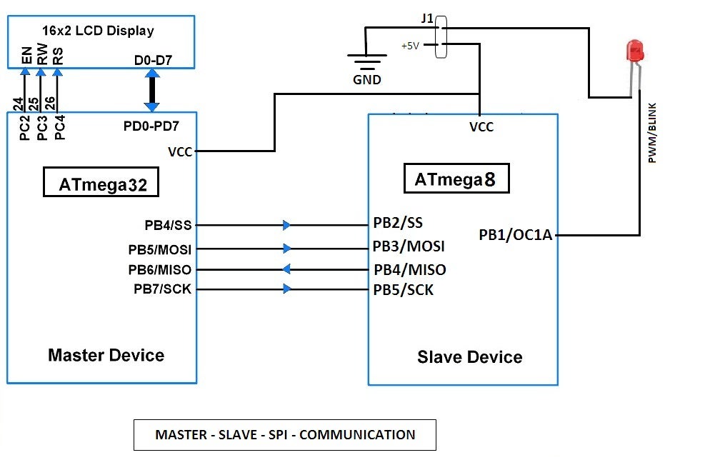
Task 6 - Make an ATmega32 - ATmega8 Master-Slave SPI Communication
Objective:
Demonstrate SPI Communication ATmega 8 & ATmega 32
Pre-requisites I learned:
Since ATmega 8 & ATmega 32 are both ICs its not possible to directly program them, you should connect both of them to an ARDUINO as in the below shown circuit diagram, and then program it.

Major Learning:
The AVR contains the following three programmable registers that deal with SPI:
- SPI Data Register (SPDR):
- Master Side:
- It's a 8 bit shift register.
- The Byte (i.e. 8 bits) to be transferred is copied into this (Data) register.
- Slave Side:
- It's a 8 bit shift register.
- The data register will now have the byte and we copy it into a register using IN instruction and then output the byte to a port.
-
SPI Status Register (SPSR):
- It's a 8 bit shift register.

-
SPI Control Register (SPCR):
- It's a 8 bit shift register.

- SPI Interrupt Enable (SPIE): Allows SPI to trigger an interrupt when data transfer is complete, so the Microcontroller Unit (MCU) can respond immediately without constantly checking. This works only if global interrupts are enabled.
- SPE (SPI Enable): The SPI Enable bit is used to enable SPI as a whole. When this bit is set to 1, the SPI is enabled or else it is disabled. When SPI is enabled, the normal I/O functions of the pins are overridden.
- Data Order (DORD): Set this bit to 1 if you want to transmit LSB first, else set it to 0, in which case it sends out MSB first.
- Master/Slave Select MSTR : This bit is used to configure the device as Master or as Slave. When this bit is set to 1, the SPI is in Master mode (i.e. clock will be generated by the particular device), else when it is set to 0, the device is in SPI Slave mode.
- SPI Clock Rate Select (SPR1, SPR0) These bits, along with the SPI2X bit in the SPSR, are used to choose the oscillator frequency divider, wherein the fOSCstands for internal clock, or the frequency of the crystal in case of an external oscillator.
Circuit Diagram:
Pin diagram of ATmega 8 & ATmega 32 are as follows:

Actual Diagram:
Couldn't complete due to the absence of 16Mhz Crystal oscillator/AVR-USB Programmer in the lab.
References:
- Click here: Understand Registers in AVR family for SPI communication
- Click here: Programming an ATmega microcontroller
- Click here: Task
Task 7- Make a Lithium-ion Battery Pack
Objective:
- Make a lithium ion battery pack with 12 cells to make a BMS supply of 44.4V, 4.8Ah, 50A cont. discharge rate (BMS limiting at 60A)
What we did?
We made a battery pack of the following configuration; Battery: ICR18650
| Type | Value |
|---|---|
| No. of cells used | 2 |
| Output supply voltage | 3.7 x 2 |
| Continuous discharge rate in Ah | 2000 mAh |
Actual Diagram:
I did this task along with Sai Suhas, who is a EvRe Batch 5 student from EEE'26.

Task 8- Working with multiple sensors
Objective:
Use any 3 sensors of your choice to provide the respective data from the sensors. Use up all of the above task to have an application in this car.
Pre-requisites I learned:
For doing this car I used almost all the knowledge which I gained during the coursework of EvRe. I have used servo motors, ultrasonic sensors, LDRs, IR sensors, Motor drivers, ESP-32 etc.
About the car:
| Components used: | |
|---|---|
| Mini Breadboard | 1 |
| L298N Motor driver | 2 |
| DC motors | 4 |
| Servo motor | 1 |
| IR Sensors | 2 |
| Ultrasonic senor | 1 |
| LDR | 2 |
| ESP32 | 1 |
| 2 kOhm Resistor | 1 |
| 1 kOhm Resistor | 3 |
My plan was to make a car which has 3 modes,
- Fully Autonomous:
- Under IR control only: Here the car would run in a fully autonomous mode solely under the control of IR sensors put on the front of the car, in this mode it can act as a line follower bot.
- Under Ultrasonic control only: Here the car would run in a fully autonomous mode solely under the control of ultrasonic sensors, the ultrasonic sensor is mounted on top of a servo motor so that the servo motor can rotate it different directions see and detect for obstacles and then move in a direction where there is no obstacles. It can act as a automatic object detecting vehicle/maze solver under this mode.
- Manual Control: Here since the car is controlled by ESP32 which supports Wi-Fi capabilities, we can control the car from our mobile as well, here the mobile acts as a remote control. In this mode we can use the car as a normal RC car where the controls of the car can be programmed and hosted on a webpage and controlled via the ESP32.
For selection of the mode the user should enter either of the 3 numbers in the serial monitor (when asked), 0 → Line Follower Mode 1 → Obstacle Avoider Mode 2 → Manual Control Mode (Wi-Fi)
Other interesting features of the car:
- It has mecanum wheels, it can move front, back, diagonally and even rotate on spot; it can be used in places where the space is very limited.
- It also has head lights controlled by LDRs, as when the lighting is less around the car, the LDR values change and therefore trigger the front LED (head light) to switch ON. Therefore it can act as a automatic head light as well. When there is low lighting the lights turn ON automatically, and turn OFF automatically when there is enough light in the surrounding.
Circuit Diagram:
This image is a very simplified version of the sensors used my car, it doesn't cover everything. This is just for understanding purpose.

Complete circuit diagram of the car:

Actual Diagram:

References:
- Knowledge of all my previous tasks till date, starting from level 0.
- Chat GPT for code
- Click here: Code