LEVEL 2
1 / 6 / 2025
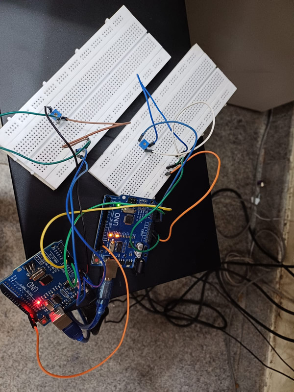
Task 2- SPI Communication
- SPI (Serial Peripheral Interface) is a synchronous, full-duplex protocol used for fast communication between a Master (e.g., one Arduino) and a Slave (another Arduino).
- It uses 4 main lines:
- MOSI (D11): Master → Slave
- MISO (D12): Slave → Master
- SCK (D13): Clock from Master
- SS (D10): Slave Select (LOW to enable slave)
- Master controls the communication using SPI.begin() and SPI.transfer(), sending data while controlling the clock and slave selection.
- SPI is faster than UART/I2C, but allows only one master and needs separate SS lines for multiple slaves.
- SPI is widely used to interface microcontrollers with devices like microSD cards for data storage, OLED/TFT displays for fast graphical output, and sensors such as accelerometers and gyroscopes for real-time data acquisition.
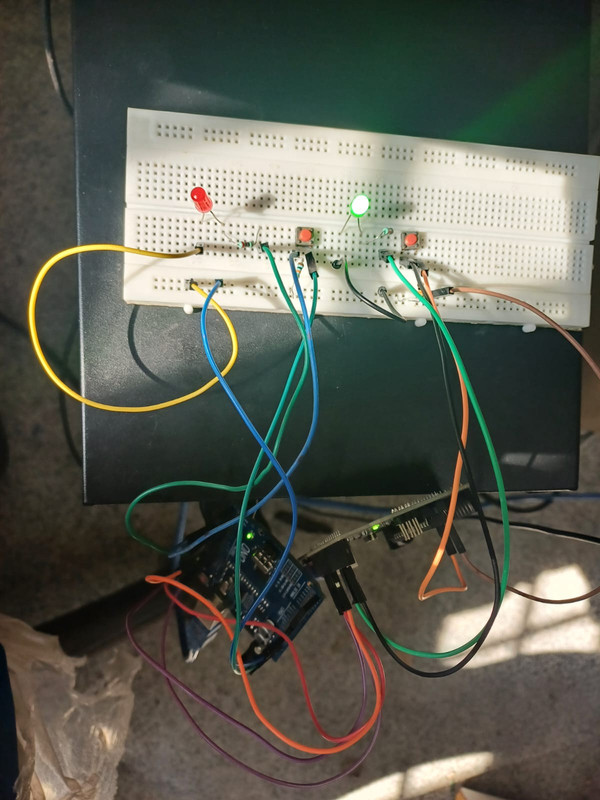
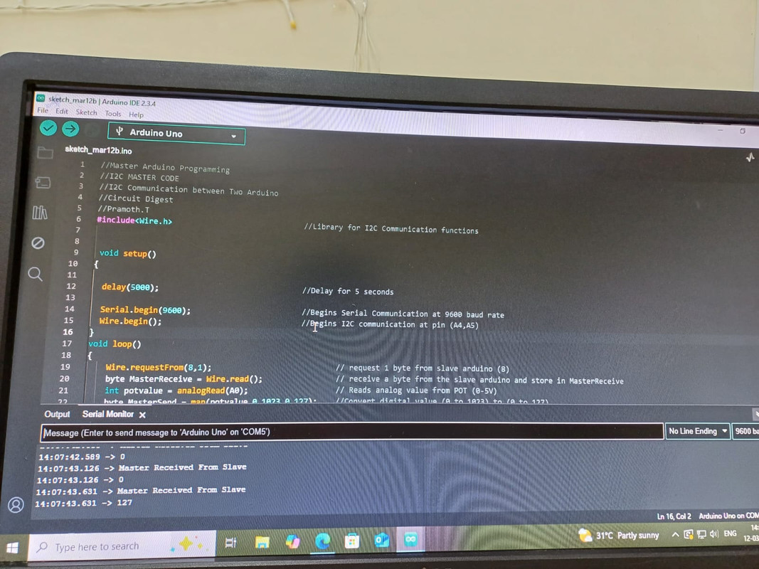
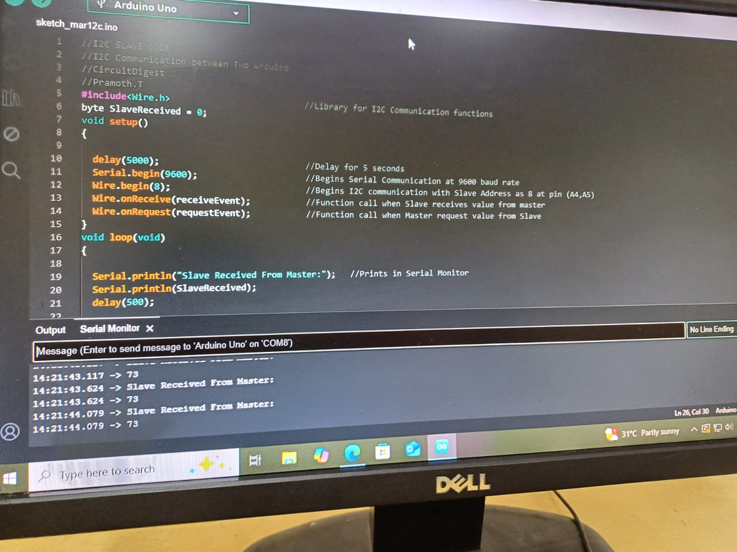
Task 3- I2C Control
- I2C (Inter-Integrated Circuit) is a two-wire, half-duplex, synchronous communication protocol for connecting multiple devices on the same bus.
- It uses SDA (data line) and SCL (clock line) shared by all devices, reducing wiring complexity.
- Devices on the bus have unique addresses; one device acts as the Master to control the clock and initiate communication.
- Data is transferred in 8-bit packets with an acknowledge (ACK) bit after each byte to confirm reception.
- Commonly used for connecting sensors, EEPROMs, RTCs, and displays in embedded systems due to its simplicity and scalability.
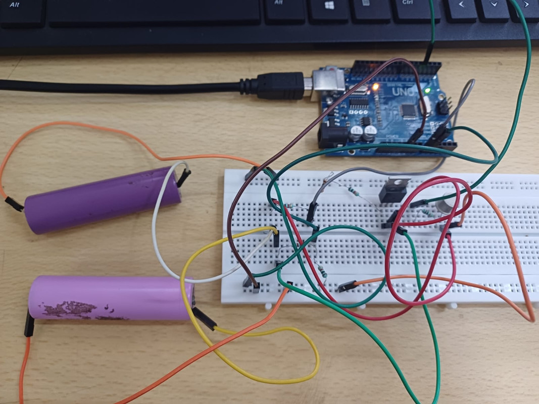
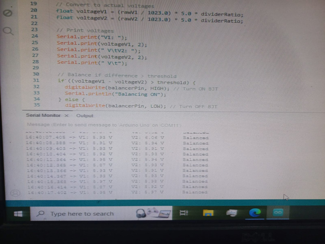
Task 6 - Smart Active Battery Balancer
- Aim- To balance two unbalanced batteries
- Actively transfers charge from higher-voltage cells to lower-voltage ones.
- Arduino Uno monitors and equalizes the voltage levels of two unbalanced Li-ion cells, by intelligently controlling current flow with an IRF830 n-MOSFET and CL100 NPN transistor.
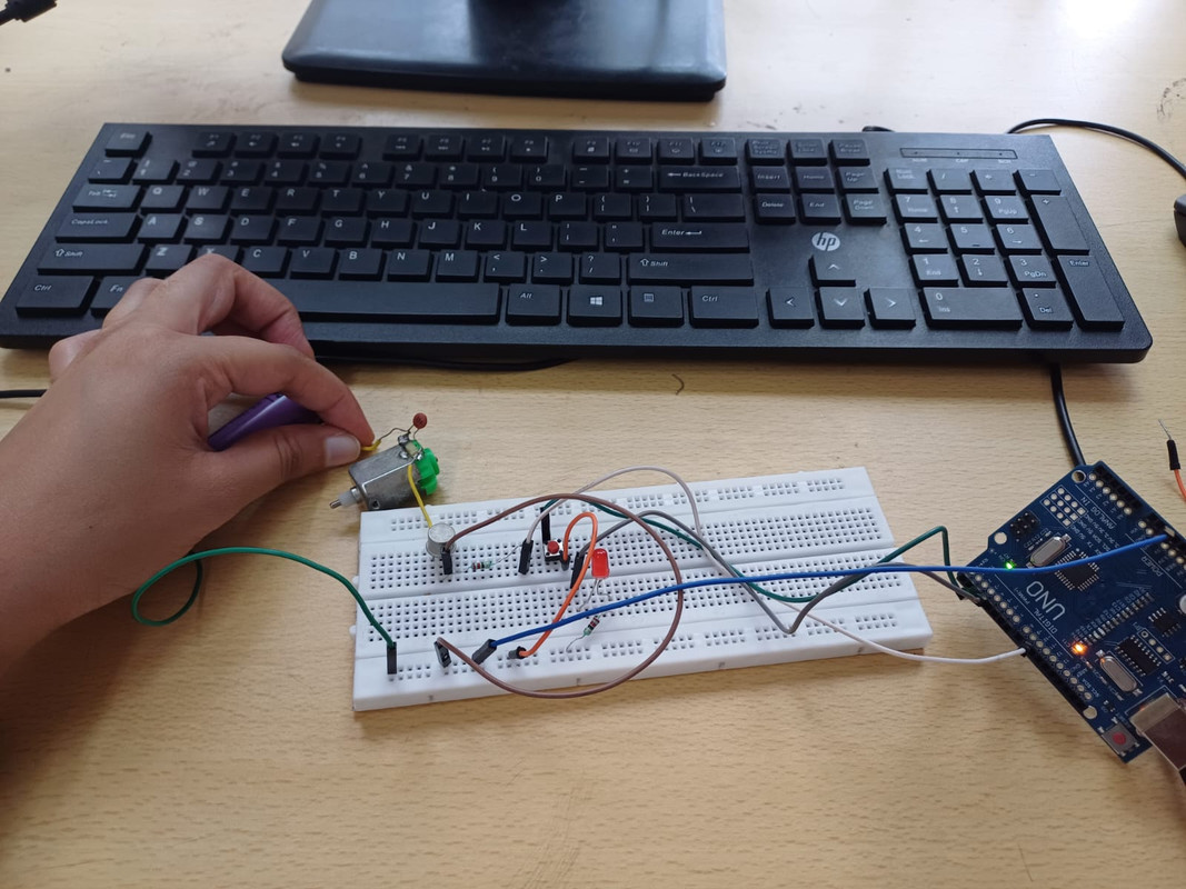
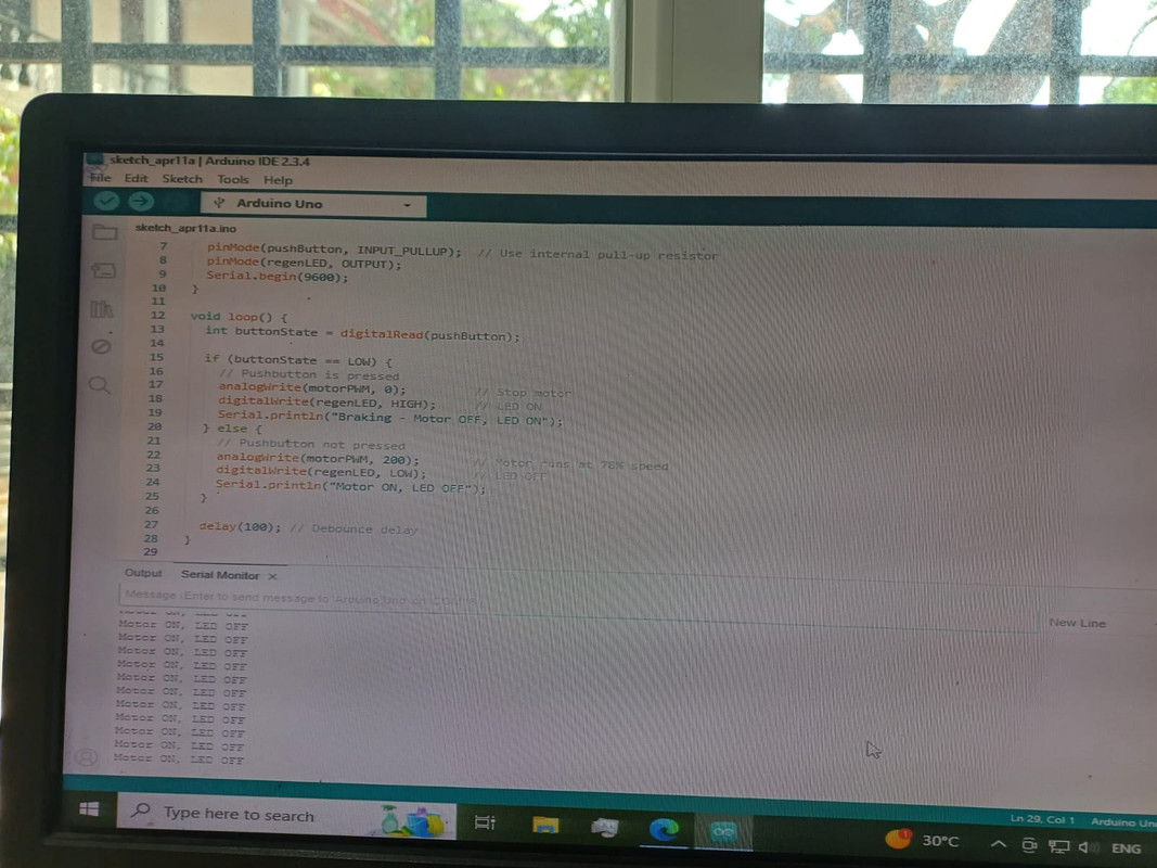
Task 7 - Regenerative Braking System Demo
- Aim- To demonstrate the concept of regenerative braking using a DC motor controlled by Arduino PWM.
- In electric vehicles, regenerative braking converts the vehicle’s kinetic energy into electrical energy during deceleration, instead of wasting it as heat.
- The motor acts as a generator, feeding energy back into the system.
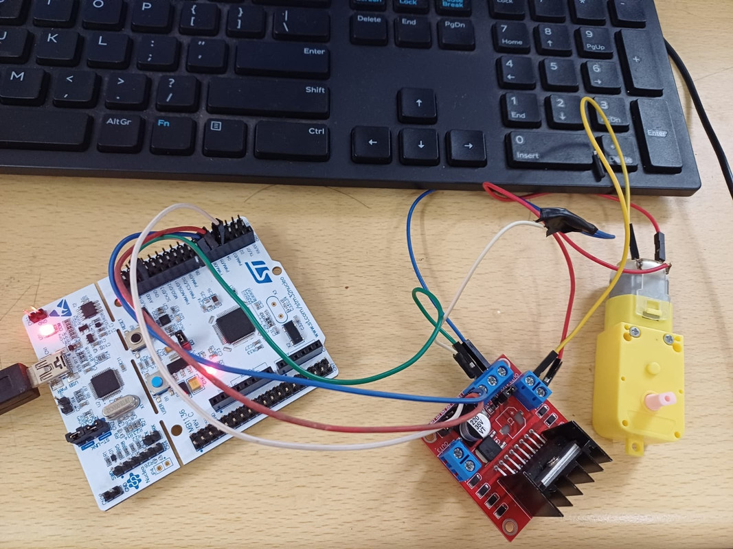
Task 8- Interfacing STM32 Nucleo with L298N Motor Driver
- L298N is a dual H-bridge motor driver used to control the direction and speed of DC motors.
- STM32 Nucleo outputs PWM signals for speed control and digital pins for motor direction.
- The motor driver receives control signals and supplies the required current to the motors.
- PWM frequency and duty cycle from STM32 regulate motor speed smoothly.
- Direction pins (IN1, IN2) determine motor rotation direction (forward/reverse).
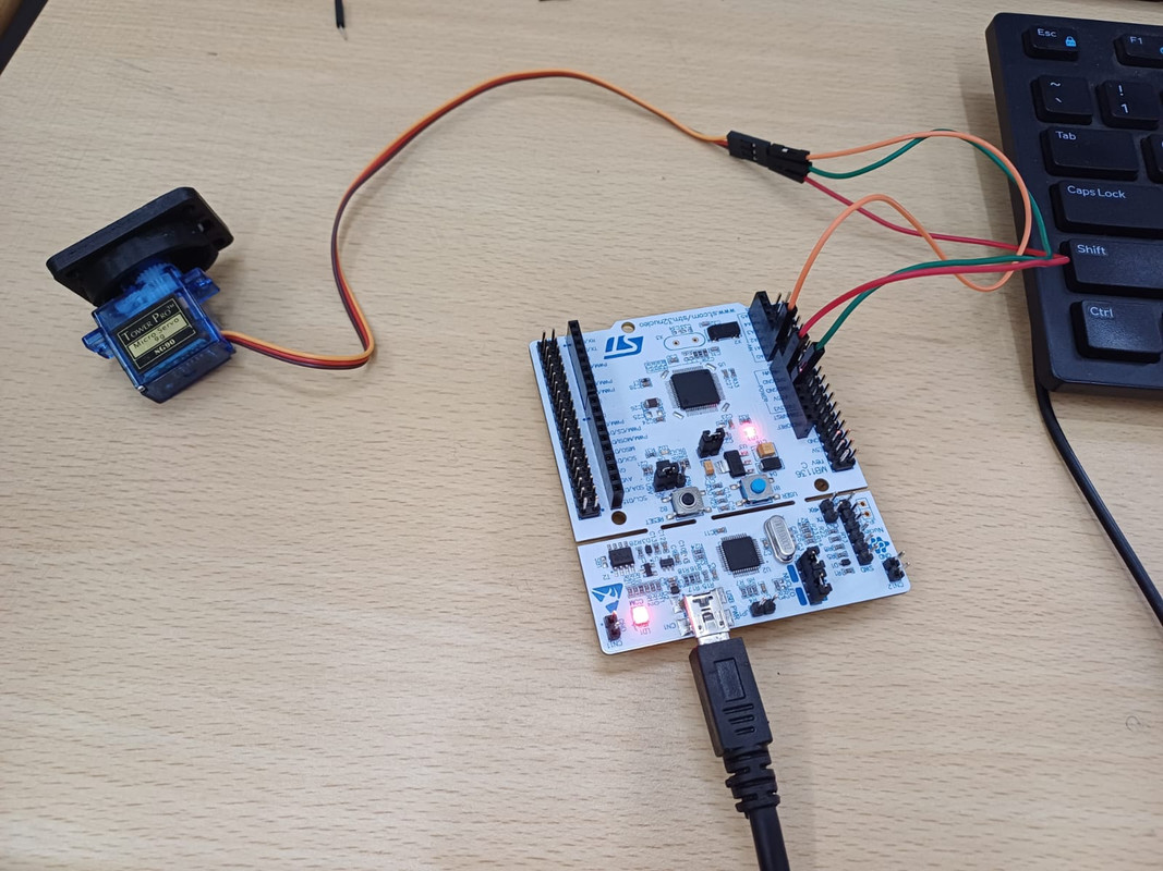
Task 9 - Interfacing STM32 Nucleo with Servo Motor
- Servo motors rotate to a specific angle based on the PWM pulse width received.
- STM32 Nucleo generates PWM signals typically between 1ms to 2ms pulse width at ~50Hz frequency.
- Changing the PWM duty cycle moves the servo shaft to the desired angle.
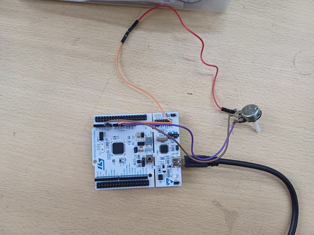
Task 10 - Configuring ADC in STM32 Nucleo Board
- ADC (Analog-to-Digital Converter) converts continuous analog voltages into discrete digital numbers.
- STM32 Nucleo’s ADC supports multiple channels and resolutions (commonly 12-bit).
- Configuration includes selecting the ADC channel, sampling time, and conversion mode.
- ADC conversion can be started manually or via hardware triggers.
- Digital values from ADC are used in firmware to interpret sensor readings or control algorithms.