
level 2 report
9 / 5 / 2025
Task 2 – SPI Communication
SPI stands for Serial Peripheral Interface. The SCK, MOSI, MISO, and SS pins of both Arduinos are connected.
- SCK (Serial Clock): Synchronizes both devices.
- MOSI (Master Out Slave In): Transfers data from the master to the slave.
- MISO (Master In Slave Out): Transfers data from the slave to the master.
- SS (Slave Select): Used by the master to choose which slave to communicate with.
The master Arduino controls SCK, generating the clock signal shared with all slaves. Slaves synchronize using this clock. The master initiates communication and selects the slave by pulling SS low. When selected, the slave listens and responds.
Data is exchanged simultaneously—when the master sends a byte using SPI.transfer(), it also receives a byte from the slave at the same time.
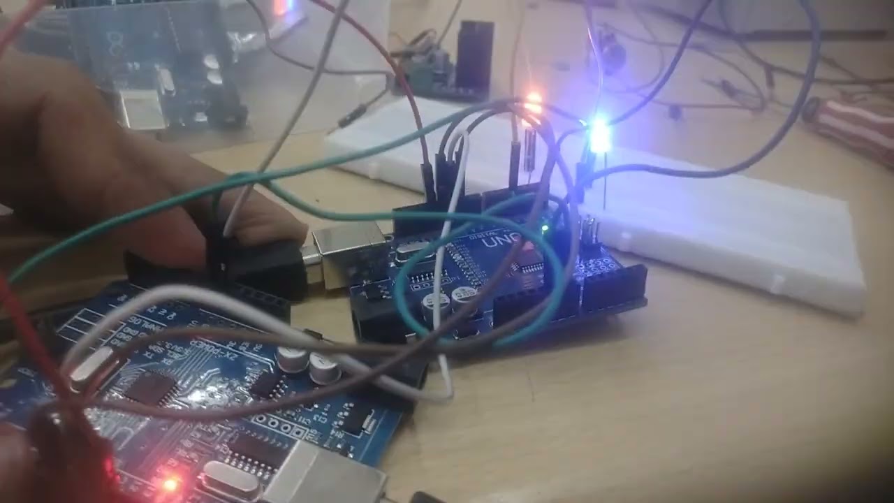
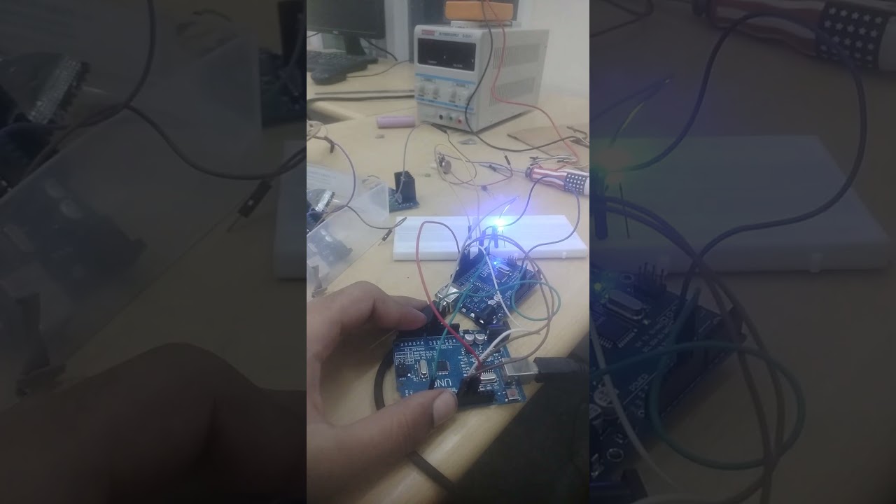
OUTPUT: since i didn't got the output using button's , i don't knew where the fault was so i choosed an alternative that is, i performed spi without using buttons and controlling the communication using the code ( i made master calling continously to the slave) as a result got the led blinking in the simultaneous fashion , here is what exactly happened , the master is sending signal to the slave ( i.e blink the led) and the slave respond to the master saying you also (blink the led) , as a result got the blinking of led in simulatneous fashion.to understand the blinking of led , master giving the high signal to slave , and slave also responding with high signal , ( as led was already high , but it gets re-triggered , as a result , it blinks again).
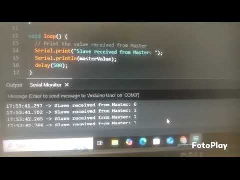
OUTPUT: so in the above video something strange happened , i got output like , first slave blinks then the master blinks , the reason for this output is , i once again uploaded the same masters and refereshed the master's interface , while the slaves code and its sketch remained same , as a result due to the processing delay , slaves led blinked first and then masters.
Task 3 – I²C Control
I²C stands for Inter-Integrated Circuit. Unlike SPI, which requires four wires, I²C needs only two:
- SCL (Serial Clock Line): Synchronizes data transfers and carries the clock signal.
- SDA (Serial Data Line): Carries data both to and from devices.
Although multiple slaves can share the bus, only one master may initiate communication at a time.
Communication Sequence:
- Start condition: The master pulls SDA low while SCL remains high.
- Data transfer: Data is sent in 8-bit chunks. After each byte, the receiver sends an acknowledgment (ACK) or non-acknowledgment (NACK) bit.
- Stop condition: The master releases SDA to high while SCL remains high.
Slave Addressing:
Before sending data, the master transmits the 7-bit (or 10-bit) address of the target slave, followed by a read/write bit.
Voltage Levels:
I²C can operate at 3.3 V or 5 V. Use a level shifter when interfacing devices at different voltages.
OUTPUT : the poteniometer reading ( which is connected to master) is shown on the slaves's serial monitor and the poteniometer reading (connected to slave) , is shown on the master's serial monitor.
Task 7 – Make a Lithium-ion Battery Pack
- Voltage simply means the potential difference — the reason current flows.
- Capacity (Ah) refers to the amount of charge a battery can store, measured in ampere-hours (Ah).
- Discharge Rate (A) indicates how much current the battery can continuously discharge without being damaged.
- BMS (Battery Management System) manages the charging and discharging of the battery pack to ensure safety and efficiency.
One lithium-ion cell typically provides 3.7 volts. For example, to achieve 44.4 volts, you would connect 12 cells in series (+ to - to +...).
- In a series configuration, voltages add up, while capacity (Ah) remains the same.
- Example cell specifications:
- Voltage: 3.7V
- Capacity: 4.8Ah
- Discharge rate: 50A
OUTPUT: since to meet the requirments of the task i needed 12 batteries , and 12 bms , since i didn't had 12 bms , even without the bms also the task is done , but it can't be safe , because we are dealing with the high voltage , and getting the cell of exact 4.8 ah and 50a is also difficult , so one can connect upto 3 batteries without the need of bms , so i connected the 3 batteries in series , got the total voltage that is the sum of individual voltage of the cell.
Task 5 – Speed Control of BLDC
Let the rating of the BLDC motor be 1000KV, meaning the motor rotates at 1000 RPM per 1 volt with no load. An ESC (30A) is used, which controls the motor and can handle up to 30 amps of current. We use the Servo library in the Arduino IDE to generate PWM signals.
PWM (Pulse Width Modulation) is like turning a switch on and off rapidly. The length of the ON time (pulse width) controls the motor speed:
- 1 ms pulse → Motor OFF
- 2 ms pulse → Motor at full speed
At 50 Hz, 50 pulses are sent per second, meaning each PWM cycle includes one ON and one OFF phase.
A potentiometer gives analog values from 0 to 1023, which are mapped by the Servo library:
0→ 1 ms (corresponds to 0°)1023→ 2 ms (corresponds to 180°)
This signal is sent to the ESC, which then controls the BLDC motor accordingly.
ESC Calibration (optional):
- Turn the potentiometer to maximum.
- Power on the ESC – the motor beeps (high point set).
- After 2 seconds, turn the potentiometer to minimum.
- Motor beeps again – low point is set.
Now, the motor will respond accurately to potentiometer input.
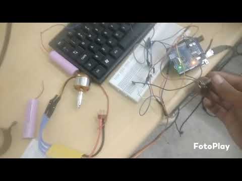
OUTPUT: when the poteniometer is set to max , the bldc motor rotated at its full speed.
TASK 1- Build Chassis
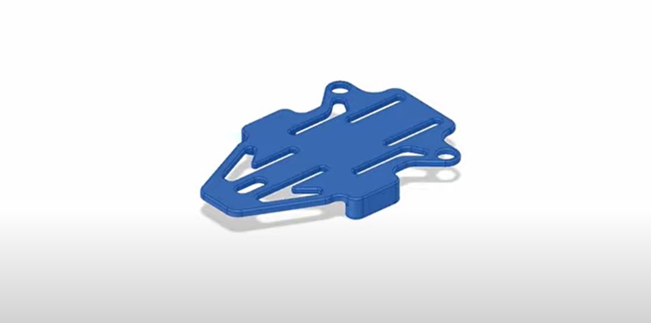
OUTPUT : Build Volume: 220 mm × 220 mm × 250 mm , the dimensions are enough for the chassis needed for my application , i want to attach only one wheel at the centre which can rotate 360 degrees , on the right side of the wheel on the above portion i want to attach battery , and on the left side of the wheel on the above portion i want to attach l298n and esp32 , considering that the battery weight is more compared to the weight off the esp32 and l298n , so the weight ratio of 40-60% i.e 40 from right and 60 from left , so while designing , giving more volume to the left side , but the weight ratio depends on the material used , and the above is the image of the chassis design which is done on fusion 360 , i took the help of a you tube video to understand the above design.