
COURSEWORK
Nitin's EV-RE-001 course work. Lv 2
| Nitin shatkar | AUTHOR | ACTIVE |
# EV-RE Level 1 Report
29 / 3 / 2025
Task 1: Utilizing Transistors as Switches and Voltage Regulators
Using Arduino to Control a Transistor as a Switch
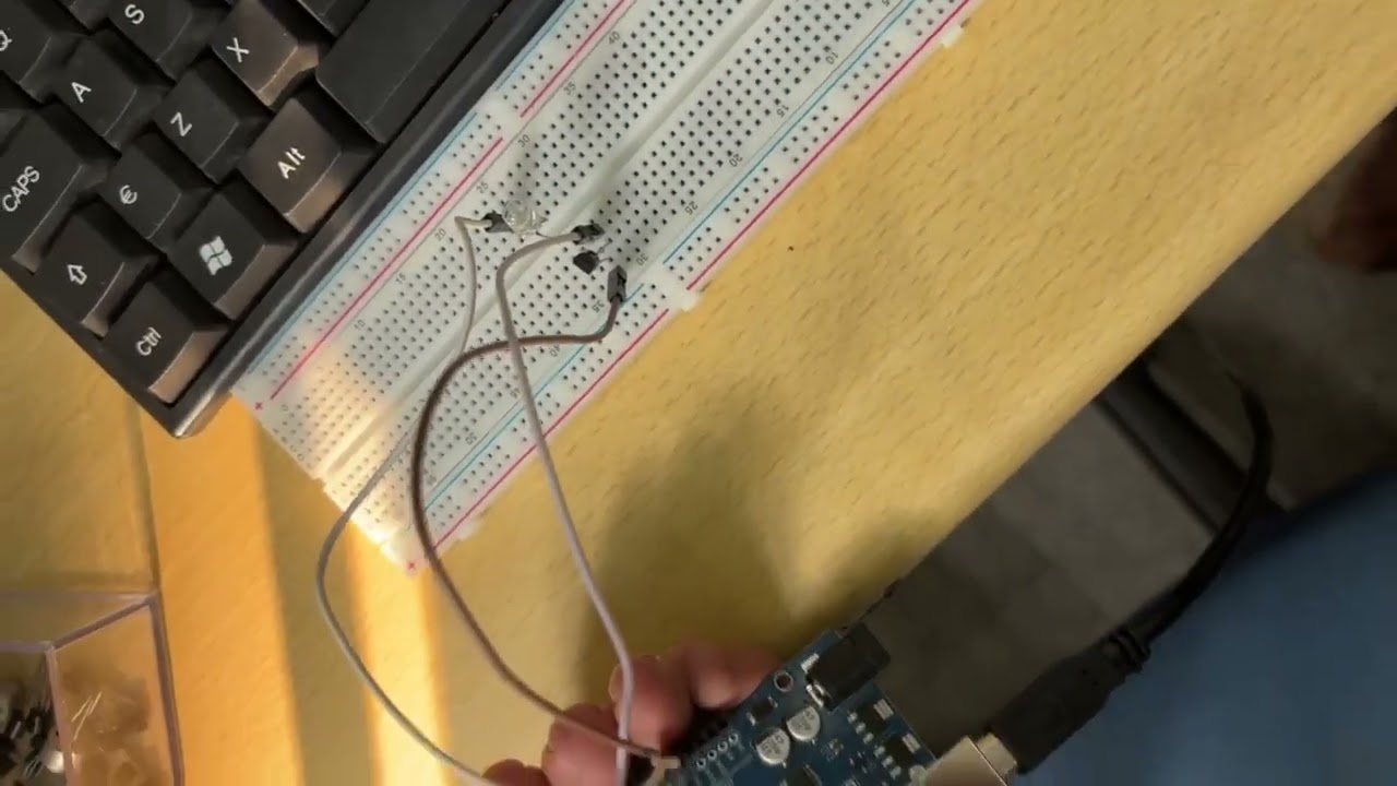
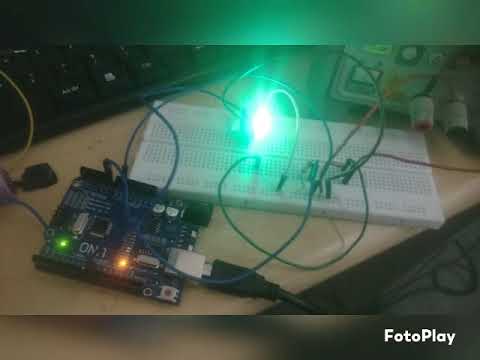
I used an Arduino to understand how transistors can function as switches. The Arduino sends a small signal to the base of the transistor, which activates it, allowing current to flow from the collector to the emitter. As a result, the LED glows.
When the Arduino stops sending the signal to the base, the transistor turns off, preventing current from flowing from the collector to the emitter. Consequently, the LED does not glow.
Using this logic, I implemented a simple LED blinking circuit. The video below demonstrates this process.
Exploring Voltage Regulation Using Transistors
Understanding the Voltage-Drop Phenomenon
I experimented with using transistors to reduce voltage by leveraging the voltage-drop phenomenon. To explore this, I simulated a simple circuit in Tinkercad.
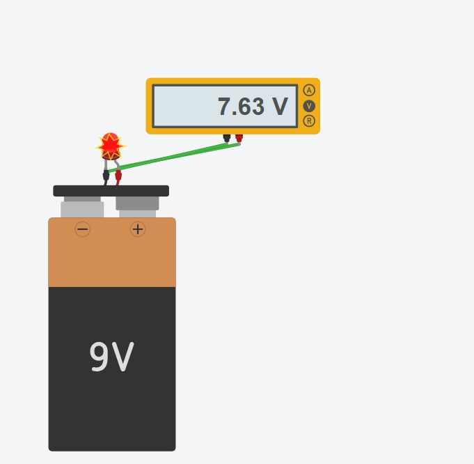
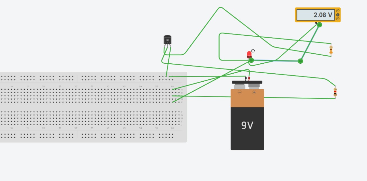
Initially, I connected an LED directly to the battery and measured a voltage of 7.63V. However, after incorporating a transistor into the circuit, the voltage across the LED dropped to approximately 2V.
This experiment helped me realize the role of transistors in voltage regulation and provided insights into the working principle of a buck converter.
Simulation Images
after using transistor :
Task 2: LED Brightness Control Using PWM and an N-Channel MOSFET
Understanding MOSFET Operation and PWM Duty Cycle
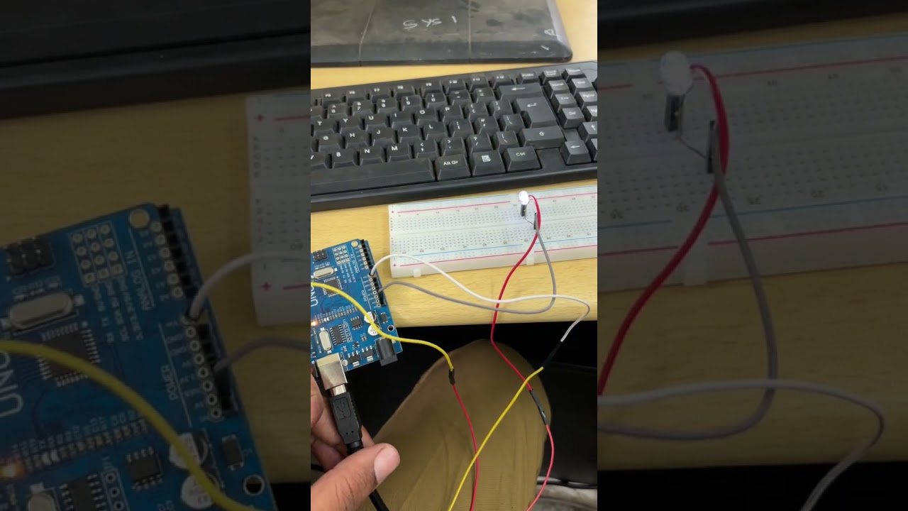
In this task, I used an N-channel MOSFET along with an Arduino to control the brightness of an LED. The Arduino sends a voltage signal to the MOSFET's gate, which allows current to flow between the drain and source, completing the circuit and causing the LED to glow. When no signal is sent, the MOSFET remains off, breaking the circuit and preventing the LED from glowing.
To adjust the brightness, I utilized Pulse Width Modulation (PWM). PWM works by rapidly switching the transistor on and off at a certain frequency. The percentage of time the transistor is on in one cycle determines the duty cycle:
- 100% duty cycle → Fully bright LED
- 50% duty cycle → Medium brightness (LED is on for half the time)
- 10% duty cycle → Dim LED (LED is on for a short period in each cycle)
This experiment helped in understanding how MOSFETs function similarly to BJTs as switches but are preferred in certain scenarios due to their efficiency and lower power dissipation.
Video Demonstration
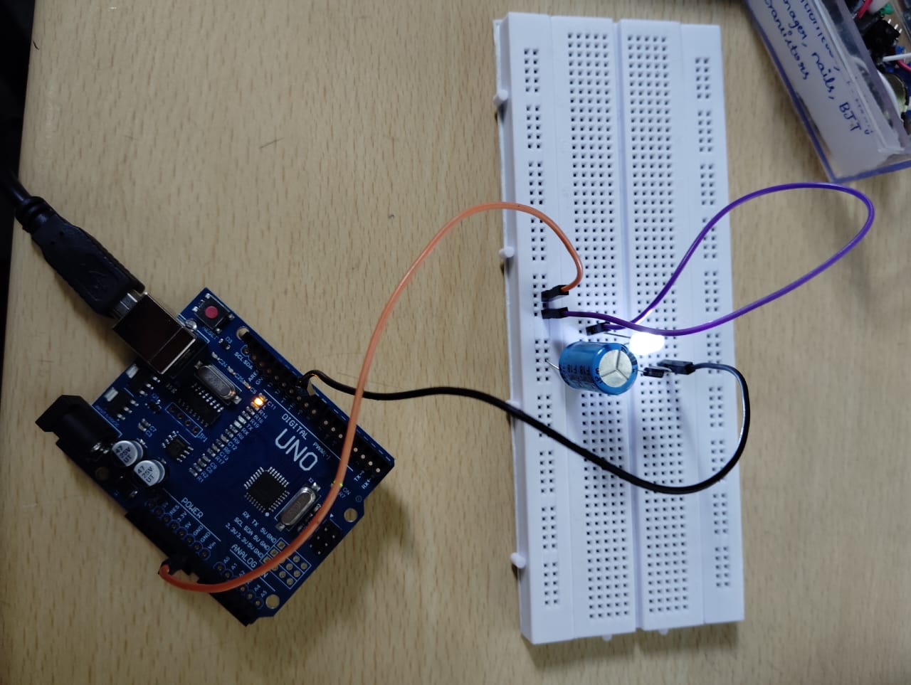
Task 3: AC to DC Conversion and Observing Direct DC vs. Rectified DC
Overview
In this task, I used an Arduino to generate AC-like signals using the PWM technique. However, since the Arduino itself cannot generate pure AC, I simulated AC using pulse width modulation (PWM) by switching a digital pin on and off.
AC to DC Conversion
To convert this simulated AC to DC, I used the half-wave rectification method, where a diode blocks the negative current, and a capacitor filters the output. As a result, the AC signal is converted into rectified DC.
Observations
When I connected an LED to a direct DC source (a battery), it glowed brighter compared to when connected to the rectified DC output.
using direct dc source :

using rectified dc :
Improving Rectified DC Efficiency
Below is a detailed article on how to increase the efficiency of rectified DC and enhance its performance.
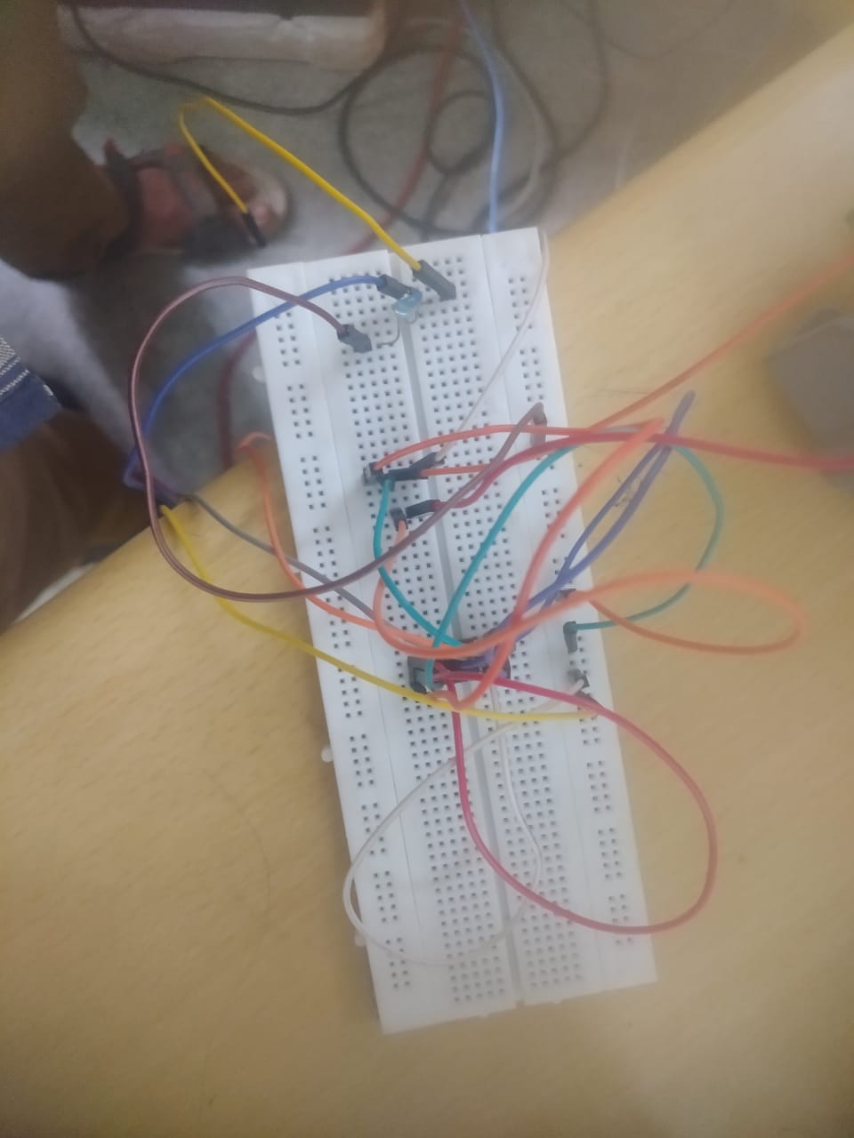
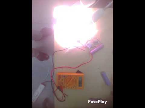
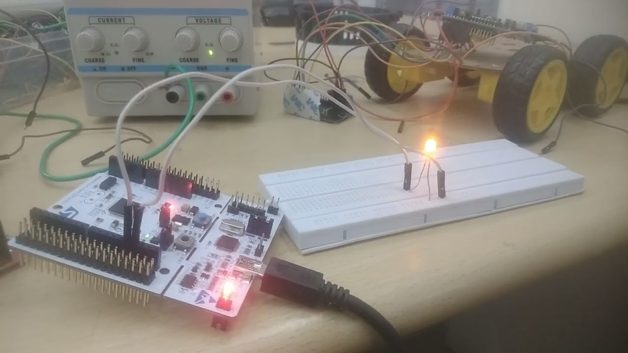
Task 4: Generating an AC-Like Signal Using a 555 Timer and MOSFETs
The 555 Timer generates a square wave signal, alternating between HIGH and LOW states. This signal is used to switch two N-channel MOSFETs in a push-pull configuration.
- When the first MOSFET turns ON, it connects the load to ground (0V).
- When the first MOSFET turns OFF, the second MOSFET turns ON, pulling the load HIGH (Vcc).
This alternating switching creates a square wave AC signal, effectively converting DC into an AC-like waveform. The MOSFETs act as power amplifiers, handling higher currents that the 555 Timer alone cannot drive.
in the below image the bulb is broken , which is the proof of amplification :
Task 6 – Temperature Detection
A diode allows current to flow in one direction only. A Bipolar Junction Transistor (BJT), like the BC547 NPN, has three terminals: Base, Collector, and Emitter. The Base controls current flow from Collector to Emitter, acting as a switch. The LM35 is a temperature sensor using a diode-connected transistor. It outputs 10 mV per 1°C rise. For example, at 25°C, it gives 0.25V. Arduino reads analog input as 0–1023 (mapped to 0–5V). Voltage is calculated using:
voltage = analogRead(pin) * (5.0 / 1024.0);
temperature = voltage * 100;
LM35 measures -55°C to 155°C.
OUTPUT : when i tried to measure the soldering gun temperature i got incorrect values because , the range of LM35 is -55°C to 155°C , but the soldering gun temp was around 300deg cel , i think due to this i didn't got the correct result , and i kept the threshold temp 5 deg cel , as a result when the temp went above 5 degree cel , i got the glowing led as a result.
to my opinion lm35 lacks very behind when it comes to sensitivity and accuracy , this was my review on lm35.
Task 7 – Temperature and Humidity Detection
The DHT11 sensor measures temperature (0–50°C) and humidity (20–90%) using a single-wire protocol. Internally, it acts like an open-collector transistor, requiring a pull-up resistor on the data line. It sends 40 bits of data: 16 for humidity, 16 for temperature, and 8 for checksum. Communication starts when Arduino pulls the data line LOW for 18 ms. The DHT11 responds with LOW and HIGH pulses, then transmits data using pulse widths (24 µs for 0, 70 µs for 1). After data transmission, it sleeps. Arduino uses micros() to measure pulse duration and decode values.
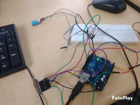
OUTPUT : i got temp value 32.00 degree cel and humidity(how much wet is the air) as 32% , i didn't used lcd because , no lcd was working , i tried 5 lcd and tried to print hello world on them to know if they are working or not , as a result it failed means lcd are not working , so i printed the results on the serial monitor.
my review about DHT-11 sensor is , its more accurate then LM35.
Task 8 – BLDC Motor and Hall Effect Sensor
A tachometer measures rotational speed in RPM. Using a Hall effect sensor and a magnet, you can build a simple tachometer. A magnet is mounted on a fan blade, and each time it passes the Hall sensor, the sensor outputs LOW. Arduino counts these LOW pulses, each representing one revolution. RPM is calculated using:
RPM = (Revolutions / Time in seconds) × 60
The Hall sensor is open-collector, so a pull-up resistor is needed. Use Arduino’s internal resistor with:
pinMode(hall_pin, INPUT_PULLUP);
Code to count one rotation:
if (digitalRead(hall_pin) == LOW) {
  if (!on_state) {
    on_state = true;
    hall_count++;
  }
} else {
  on_state = false;
}
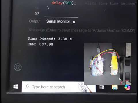
OUTPUT : i didn't used bldc motor here , instead of that i used a simple dc fan , the reason for this is , i didn't knew where to attach magnet on the bldc , since there is no blade like configuration on bldc , which was there on a dc fan , so for this reason i used dc fan.
and my review on this sensor is , it is not that accurate , we got a huge range of values , but after some efforts got some real and trustable values.
Task 9 – Battery Capacity Measurement
A battery's capacity, measured in milliamp-hours (mAh), indicates how much current it can supply over time. NPN transistors are used here for low-side switching, placing the switch between the load and ground. To monitor battery voltage, a voltage divider (two resistors) scales high voltage for Arduino input. If voltage drops below a threshold, Arduino turns off a MOSFET to cut the load. The MOSFET’s gate is controlled via a digital pin. For single cells, no divider is needed, but for multiple cells, it is essential for safe measurement.
OUTPUT : i didn't remeber exactly what threshold i kept , but yes the task was done , but i also took the help of vrps ,as there were no soldered batteries , and i didn't knew soldering that much as a result got very much difficulties in connecting the setup to the battery , so used vrps , and it worked , above the threshold the bulb glowed and below the threshould the bulb didn't glown.
Task 10 – Battery Charging
Solar panels generate DC electricity, typically 6V at 100 mA, with output between 5V–7.5V. A diode is placed between the panel and battery to prevent reverse current flow at night. It drops about 0.7V. The TP4056 module is used for charging lithium batteries, providing voltage regulation and safe charging. Charging occurs in two phases: Constant Current (CC), where high current charges the battery quickly, and Constant Voltage (CV), where voltage is held at 4.2V as current tapers off. Charging ends when current drops below 1/10th of its peak value.
 OUTPUT: i got a small increase in voltage , after using two pannels and two source of lights.as initially my solar pannel voltage was not more then my battery voltage , but later with more source of light some how i made the voltage level around the battery voltage . so charging was done
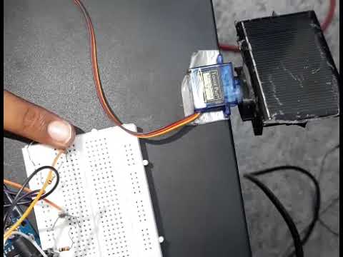
Task 13 – Solar Tracker
Two LDRs are placed on either side of a divider. When both receive equal sunlight, the servo remains still. If one LDR gets more light, the Arduino rotates the servo, moving the solar panel toward the brighter side. LDR resistance decreases with light (100Ω–1kΩ) and increases in darkness (up to 100kΩ). Since Arduino reads voltage, not resistance, a voltage divider is used—comprising an LDR and a fixed 10kΩ resistor. Connected as: 5V → LDR → A0 → 10kΩ → GND. As light increases, more voltage drops across the 10kΩ resistor, and A0 reads a higher voltage.
Watch the Video:
Task 15 – Blink LED with STM32
To blink an LED using STM32, the Blue Pill board uses a TTL converter, FTDI module, ST-Link debugger, or bootloader to upload code, while the Nucleo board allows direct upload via USB. Set pin PA5 as a GPIO output in System Core > GPIO, with mode as Output Push-Pull, speed as Low or Medium, and No Pull for pull-up/down. Connect LED: positive to PA5 and negative to GND. For the Nucleo board’s inbuilt LED, simply write code to toggle PA5, as it is the default LED pin.
Task 17 – Auto Night Lamp Using LED for Electric Vehicles (EVs)
When the LDR is blocked or there's no sunlight, its resistance increases, lowering the voltage at pin A0. This causes the LED to turn on. Since Arduino can supply only up to 40 mA, and EV lamps require 100 mA to 1 A, a transistor is used as a gate. The Arduino sends a small signal to the transistor’s base, allowing higher current from an external 12V battery to power the lamp. For currents below 200 mA, BJTs are used, while MOSFETs are preferred for currents above 200 mA due to better power efficiency.
Task 1 - LTspice and KiCad
555 Timer IC: A Simple Guide
The 555 Timer IC is a widely used component in electronic projects due to its simplicity and versatility. It can generate precise timing pulses and is available in two main modes:
- Astable Mode: Produces continuous square wave pulses, useful for applications like PWM, LED blinkers, and clock generation.
- Monostable Mode: Generates a single pulse in response to a trigger, ideal for time delays.
Applications include LED blinking, PWM (Pulse Width Modulation), tone generation, and time delays.
With its low cost, ease of use, and reliability, the 555 timer is an essential component for both beginners and experienced hobbyists!
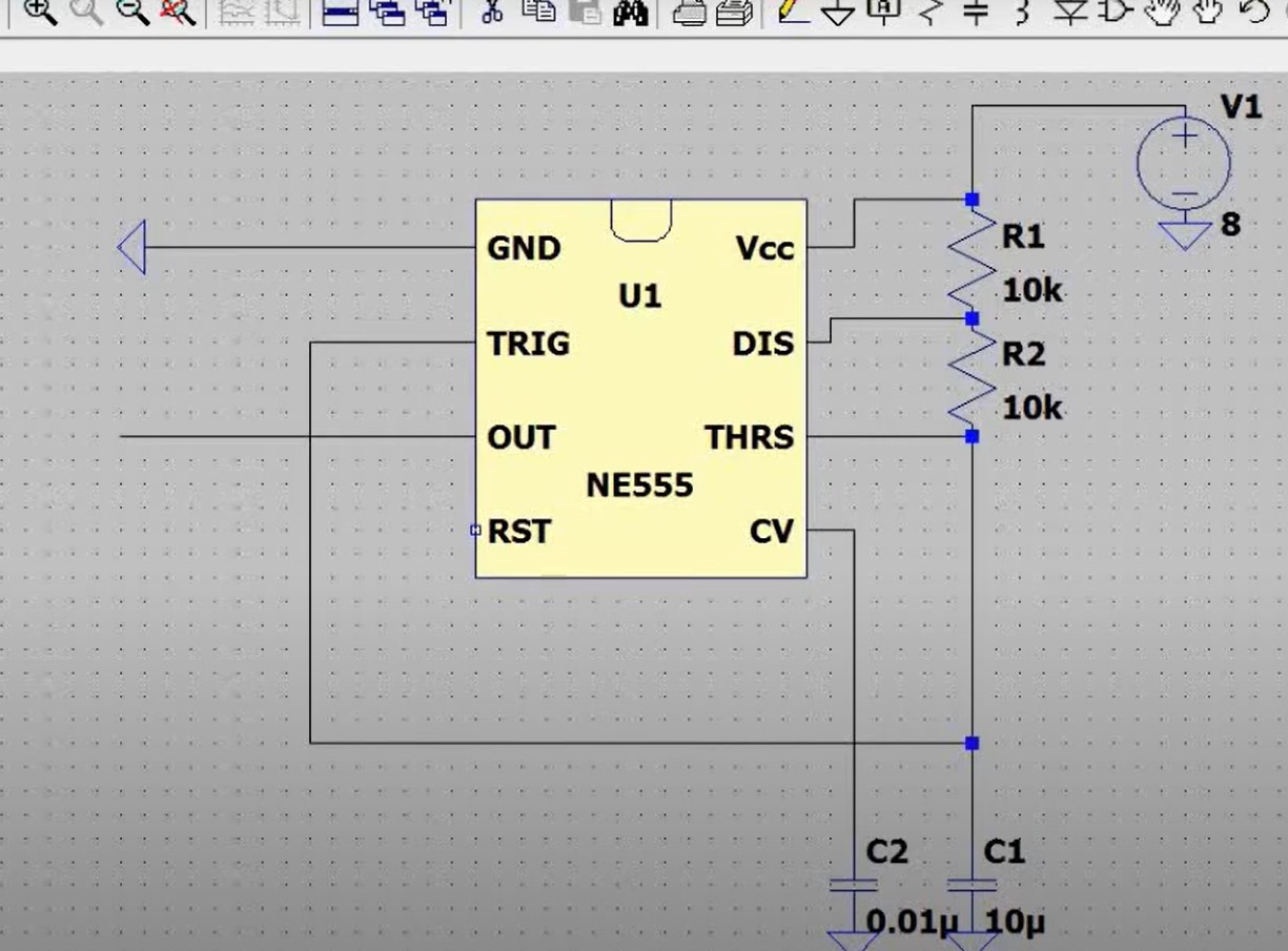
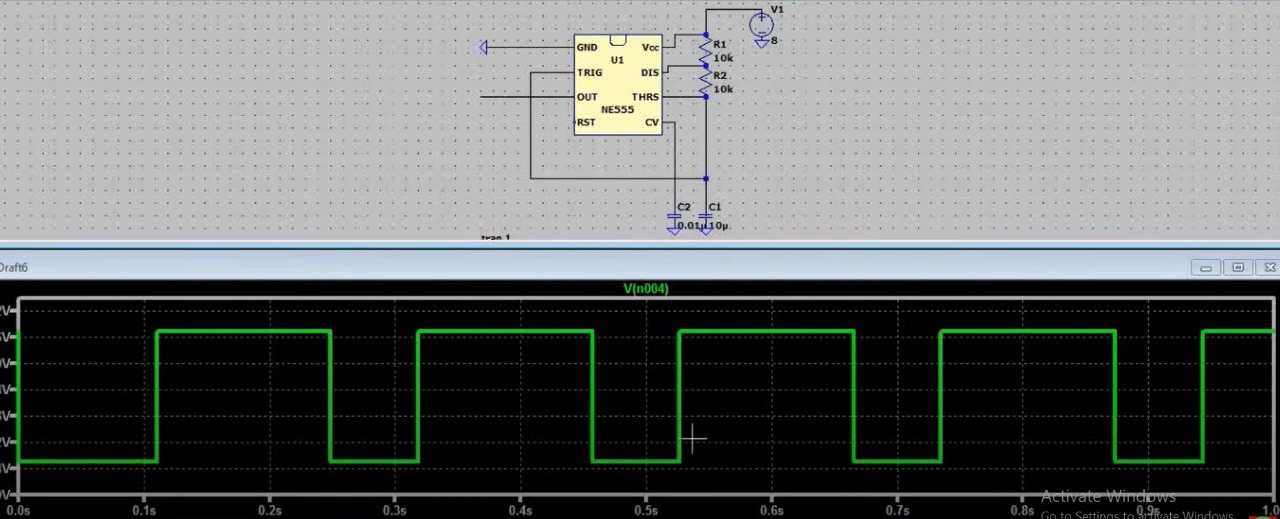
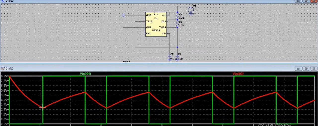
output : i got the frequency of 4.8 htz and the duty cycle of 75%
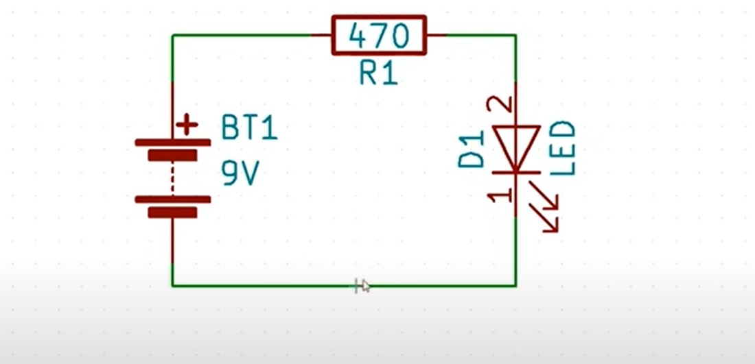
output : the above is the simple circuit diagram of an led , battery and resistor , the value of battery is 9 v and the value of resistor is 470 ohm.
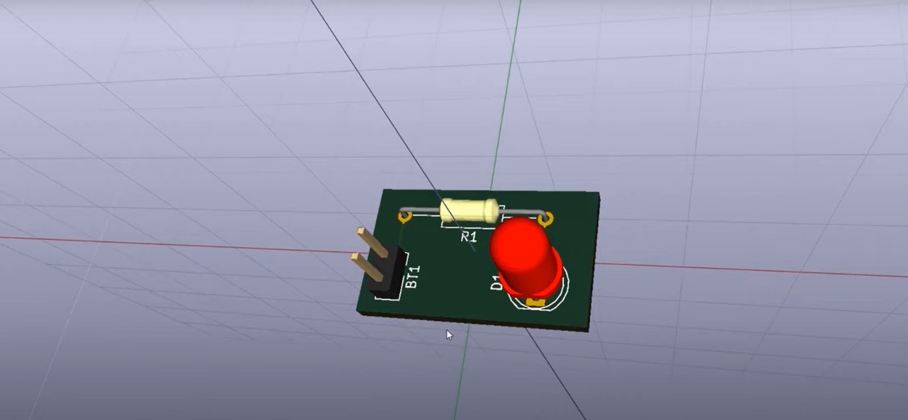
output : after assigning the foot prints to the components from there respective library , and then generating the net list , and from that net list choosing the components and making them to print on circuit board , so the above is the 3d view of the circuit printed on the printed circuit board
Task 14 - Simple Electric Circuits Simulation on MATLAB
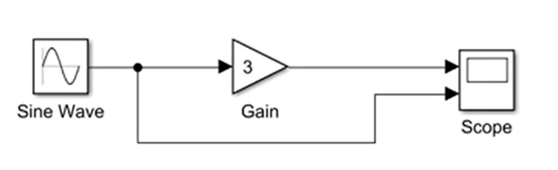
output: the above one is the very simple circuit stimulated in the matlab simulink , using the sine wave block from the sources library of the simulink's library , and the gain block and the scope to see the output , and then generating the stimulation , the value for the amplitude of the sin wave block is 2 and the value for the gain block is 3 .
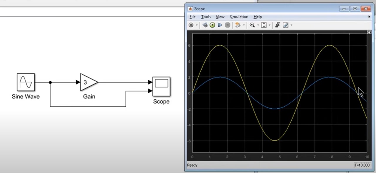
so the above image showing the output i.e is 2 amp sin wave , and the 6 amp sinwave(because of using 3 unit gain block)