13 / 10 / 2026
TASK 1: INTRODUCTION TO ESP32 AND BASIC COMPONENTS
Task 1a: Theory: Digital I/O & Interrupts
Objective: Study GPIO configuration and interrupts for efficient input handling.
Learnings and Outcomes:
1.Understanding of GPIO pins and their use in connecting external devices.
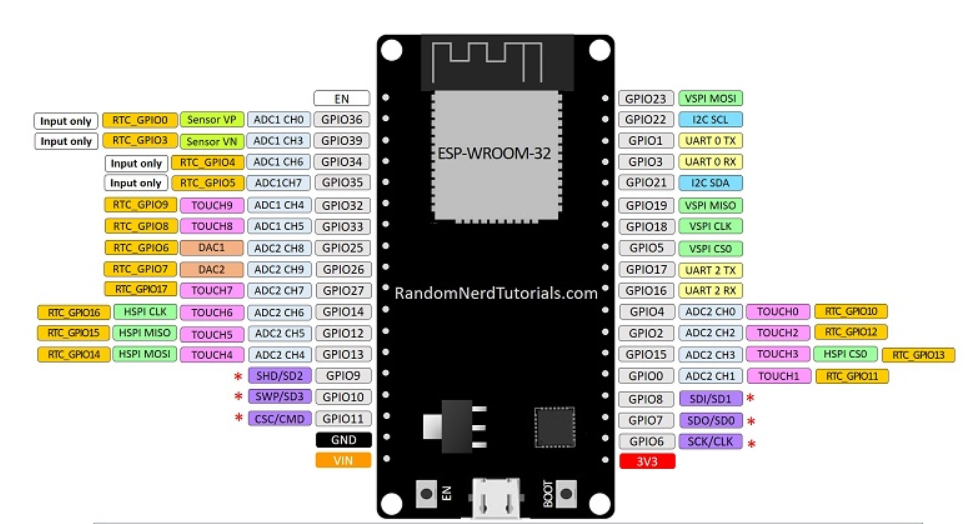
2.Awareness of ESP32 pinout and selection of safe GPIOs.
3.Ability to configure GPIO pins as input or output.
4.Knowledge of floating inputs and their problems.
5.Understanding the role of pull-up and pull-down resistors.
6.Clear idea of polling vs interrupt-based input handling.
7.Understanding how interrupts provide fast response to inputs.
8.Knowledge that interrupts improve efficiency and save CPU time.
This task builds a clear understanding of ESP32 GPIO configuration and interrupt-based input handling.
Task 1b: Simon Says Game using ESP32
Objectives: Familiarize with the ESP32 microcontroller by creating an engaging game.
Learnings and Outcomes:
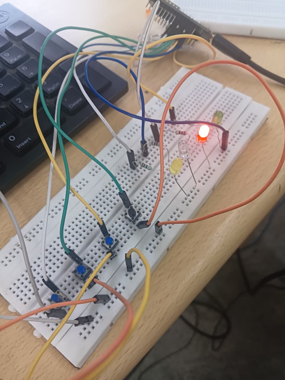
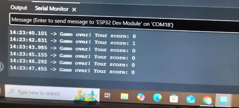
I built a Simon Says game using ESP32 with 4 LEDs and buttons. The ESP32 shows a random color sequence, and I repeat it using the buttons. Each correct round adds a new step. A mistake triggers a game-over sound and restarts. This project helped me learn GPIO control, button inputs, random logic, and real-time game handling in a fun way.
Components used:
ESP32 – The main controller handling logic and timing.
4 LEDs – Represented the color sequence.
4 Push Buttons – User inputs to match the sequence.
Resistors – Pulldown for buttons and current limiting for LEDs.
click here to view the code
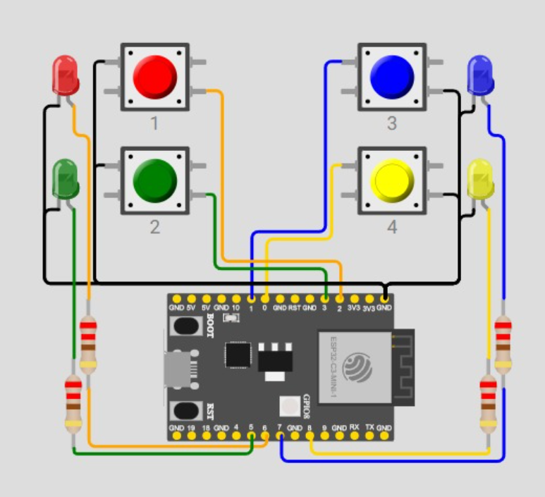
Connection I reffered:
TASK 2: TEMPERATURE BASED FAN CONTROL
Objective: Automate fan (DC motor) control using a temperature sensor and relay.
Learnings and outcomes:
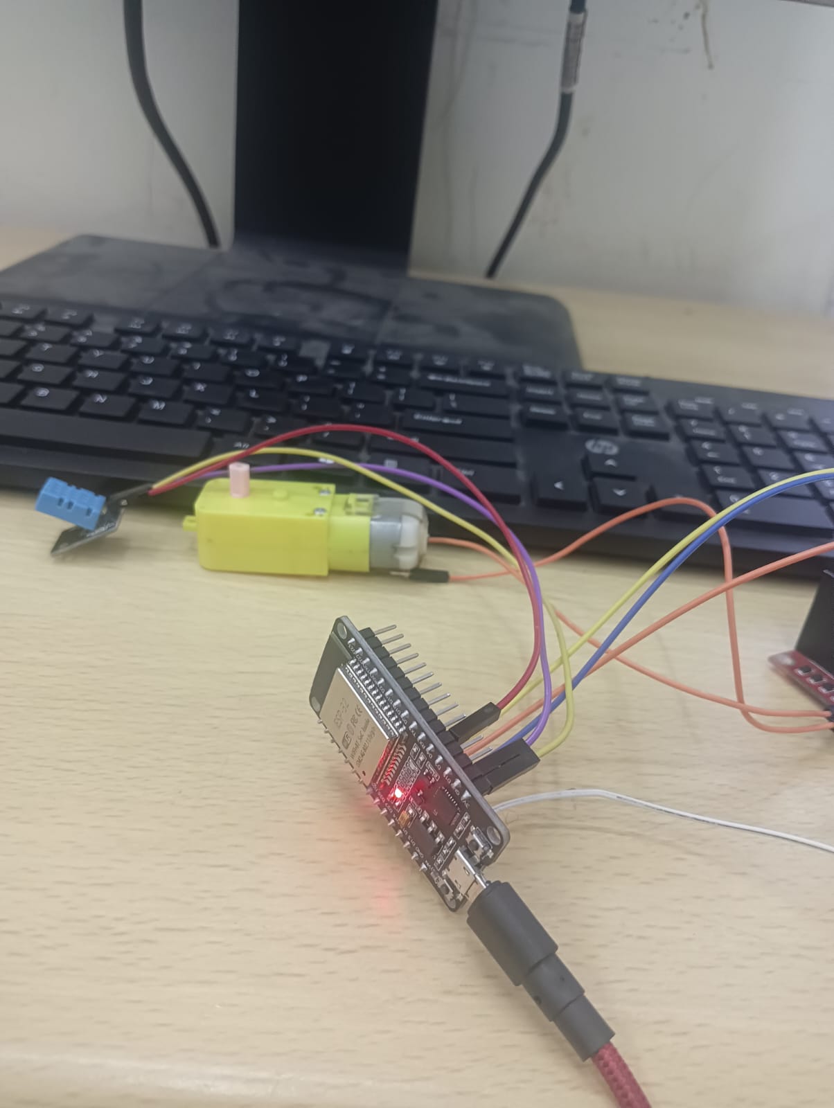
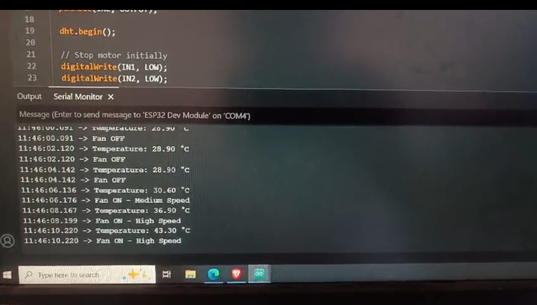
I did this task by first connecting the DHT11 sensor to read the room temperature and checking the values on the serial monitor. Then I fixed a temperature limit in the code and connected a motor driver with a DC motor. Whenever the temperature crossed that limit, the program automatically turned the fan on and adjusted its speed based on the readings.
 click here to view the code
TASK 3: COMMUNICATION PROTOCOLS
Task 3a: IoT Communication Protocols
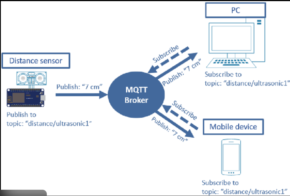
Objective: Understand IoT and Serial protocols: MQTT, HTTP, I2C, SPI.
Outcomes and Learnings:
- Understood different IoT communication protocols like MQTT, HTTP, and CoAP.
- Learned how MQTT is lightweight and suitable for real-time IoT data.
- Understood HTTP’s request–response model for web-based communication.
- Learned the basics of serial protocols (I2C, SPI) for device-level communication.
- Gained clarity on selecting the right protocol based on speed, power, and use case.
Task 3b: Controlling LEDs Using MQTT
Objective: Utilize any MQTT platform to establish publishing and subscribing functionalities.
Learnings and Outcomes:
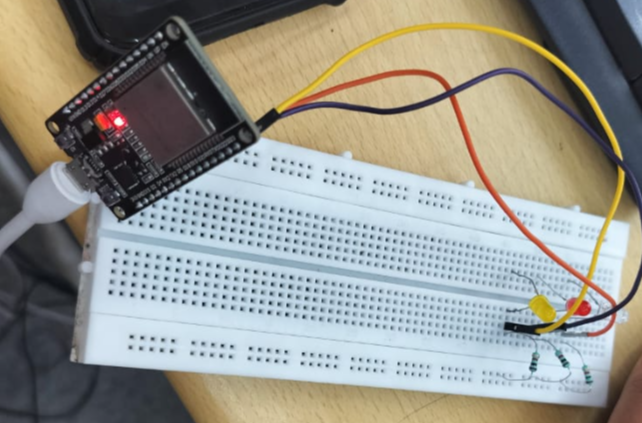
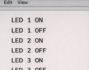
The goal of this task was to set up an MQTT-based system to control three LEDs through a cloud broker. I used HiveMQ as the public MQTT broker, where a Python script acted as the publisher and an ESP32 worked as the subscriber. The script sent simple messages like “LED 1 ON” or “LED 2 OFF,” and the ESP32 responded by switching the correct LED ON or OFF based on the message received. This felt like remotely controlling hardware using the internet and helped me clearly understand how cloud-based communication works in IoT systems.
Steps followed:
- Set up the ESP32 and connected it to Wi-Fi.
- Connected three LEDs to the ESP32 pins.
- Programmed the ESP32 using Arduino IDE to work with MQTT.
- Used broker.hivemq.com as the cloud MQTT broker.
- Subscribed the ESP32 to the led control topic.
- Sent LED ON/OFF commands using MQTT Lens / HiveMQ Web Client.
- The ESP32 read each message and switched the correct LED.
- Tested everything in real time to make sure the LEDs responded properly.
click here to the view the subscriber code.
TASK 4: SENDING DATA TO THINGSPEAK AND CREATING A REGRESSION MODEL
Objective:
Publish temperature data from ESP32 to ThingSpeak.
Retrieve the dataset from ThingSpeak for analysis.
Using Matplotlib in Python, plot the graph of Temperature vs. Time.
Create a regression model to analyze the relationship between Humidity (from a DHT11 sensor) and Moisture Percentage (from a capacitive soil moisture sensor).
Learnings and Outcomes:
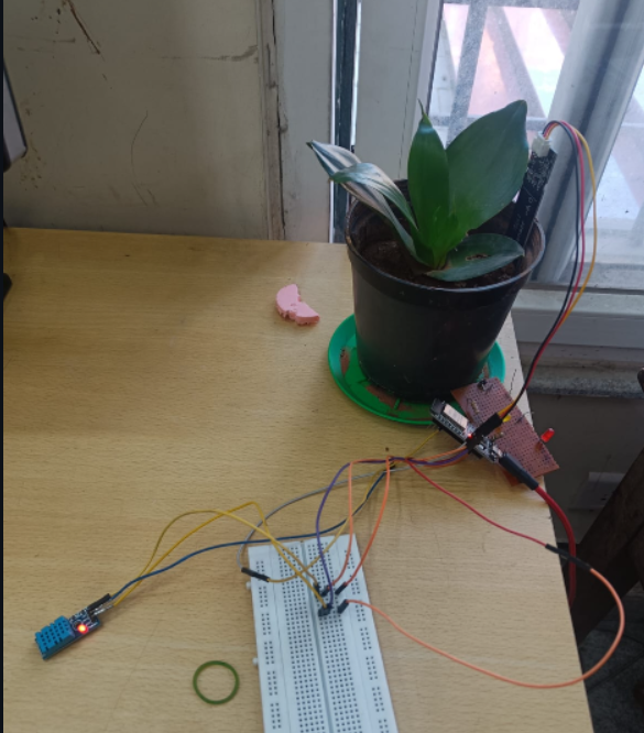
- The ESP32 interfaces with a DHT11 sensor to acquire temperature and humidity data and a capacitive soil moisture sensor to measure moisture percentage.
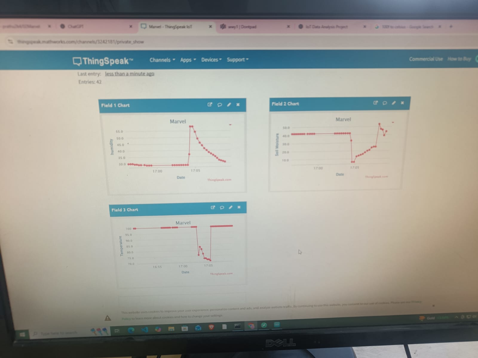
- Sensor readings are uploaded to the ThingSpeak cloud using HTTP API write requests.
- The stored data is retrieved from ThingSpeak for offline processing and analysis.
- Python is used for data handling and analysis.
- Matplotlib is used to visualize relationships through plots such as Temperature vs Time, Temperature vs Soil Moisture, and Humidity vs Soil Moisture.
- A linear regression model is implemented to analyze and predict the relationship between humidity (independent variable) and soil moisture (dependent variable).
- The results are visualized using a regression plot, enabling trend analysis and prediction.
 click here to view the code to send the data to thingspeak.
click here to view the ml code.
TASK 5: FLASHING MORSE CODE
Objective: Create a website that converts typed input (normal words) to Morse code. The LED should blink according to the Morse code generated.
Learnings and Outcomes:
The project involved using an ESP32 microcontroller to receive messages through a web server and convert them into Morse code, which was then displayed using an LED. The ESP32 mapped each character to its Morse code equivalent and blinked the LED with precise timing short blinks for dots and long blinks for dashes. This project strengthened my skills in ESP32 programming, web server hosting, and Morse code encoding, while providing practical experience with embedded systems and real-time applications.
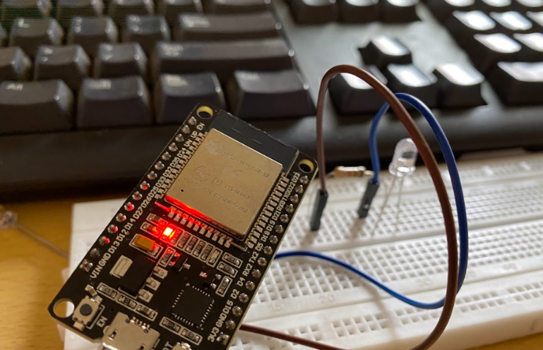
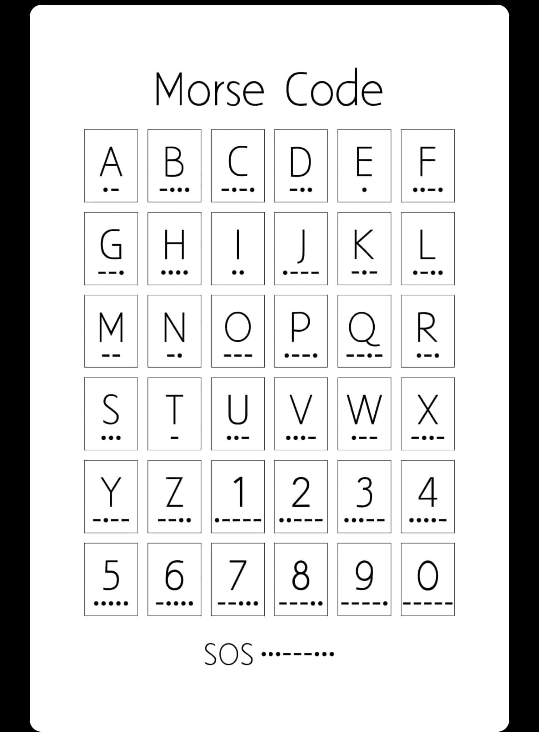 click here to view the code.
TASK 6: FIRE ALARM SYSTEM WITH SMS ALERT
Objective: Learn about fire detection and integrating SMS alert systems using APIs.
Learnings and Outcomes:
An Infrared Flame Sensor detects fire by sensing the infrared (IR) light emitted from flames. In this project, I used the flame sensor along with an ESP32 microcontroller and an LED to create a simple fire alarm system. The sensor has an IR receiver (a photodiode or phototransistor) designed to detect the specific wavelengths produced by fire. When it senses a flame, it sends a digital LOW signal to the ESP32, which then turns on the LED as a visual alert. The ESP32 is also connected to Wi-Fi, allowing it to send email notifications to designated recipients, providing remote fire alerts.
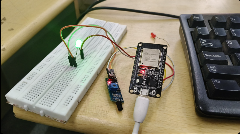
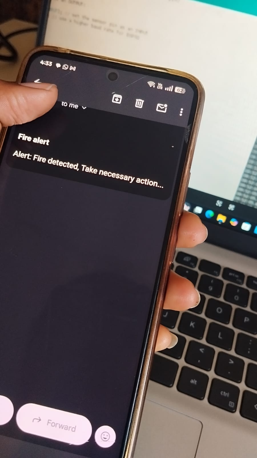 click here to view the code.
TASK 7: COMMUNICATION USING I2C PROTOCOL
Objective: Both ESP32 boards should host web servers for bidirectional communication. The typed message on one webserver should be displayed on the LCD connected to the other ESP32.
Learnings and Outcomes:
I2C stands for the inter-integrated controller. This is a serial communication protocol that can connect low-speed devices. It is a master-slave communication in which we can connect and control multiple slaves from a single master. In this, each slave device has a specific address.
Advantages:
. It supports flexible data transmission rates.
. It supports long-distance communication than SPI.
. Each device on the bus is controlled separately.
. It increases the complexity of firmware or low-level hardware.
. This protocol requires only two cables.
. The devices can work as both master and slave.
These are some few key points abt I2C.
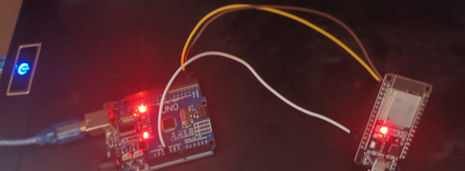
Firstly, i tried to create a master slave using 2 esp32, but i didn't get the expected output.So , i tried doing it by using 1 arduino and 1 esp32. everything went well ,due to unknown reason, message don't displayed in the screen.
Below are some key points, i learned from reading the resource article:
- Understood the I2C protocol architecture, including synchronous communication, SDA/SCL lines, and shared bus operation.
- Learned how to configure the ESP32 I2C peripheral in both master and slave modes using the Wire.h library.
- Gained clarity on I2C addressing (7-bit addressing) and the importance of matching slave addresses between devices.
- Learned the use of callback functions (onReceive(), onRequest()) for handling data reception and transmission on the slave side.
- Understood how beginTransmission(), write()/printf(), and endTransmission() manage master-to-slave data transfer.
- Learned how requestFrom() and buffer handling are used for slave-to-master data reading.
- Gained insight into bus initialization parameters such as SDA/SCL pin selection and clock frequency.
- Encountered issues in ESP32 slave communication, leading to a better understanding of timing constraints, buffer handling, and library limitations.
- Compared ESP32–ESP32 and Arduino–ESP32 I2C setups, learning about compatibility differences and stability concerns.