
PROJECT
Analog Proximity Sensor
| Vishnu S | AUTHOR | ACTIVE |
| Aditya Pattavardhanam | COORDINATOR | ACTIVE |
Analog Proximity Sensor — Project Report
Project Title: Analog Proximity Sensor
Project Type: Analog Electronics / Capacitive Proximity Sensing
Member: Vishnu S
1. Abstract
The circuit is based primarily on a CD4093 NAND Schmitt-trigger IC and an MCP602 dual operational amplifier. The prototype operates from a regulated 5 V supply and does not require a microcontroller. The project demonstrates capacitive sensing, oscillator circuits, frequency mixing, analog signal processing, filtering, and contactless human interaction.
2. Introduction
The Analog Proximity Sensor uses the change in capacitance caused by a human hand approaching a conductive sensing electrode. Instead of using a digital sensor module or microcontroller, the sensing and signal-processing functions are implemented using passive components, a CD4093 Schmitt-trigger IC, and an MCP602 operational amplifier.
The project is inspired by the operating principle of a Theremin, where changes in hand position alter an oscillator frequency and produce a corresponding change in an audible tone. The main objective here is to demonstrate the analog proximity-sensing principle.
3. Objectives
- Design and build a simple analog proximity sensor.
- Demonstrate capacitive proximity sensing using a metal electrode.
- Generate oscillator signals using a CD4093 Schmitt-trigger IC.
- Use a reference oscillator and a variable oscillator for frequency comparison.
- Process the resulting signal using an MCP602 operational amplifier.
- Produce an audible output corresponding to changes in hand proximity.
- Implement the prototype without a microcontroller.
- Study practical effects such as noise, stray capacitance, and RF interference.
4. Working Principle
The sensor operates using capacitive proximity sensing.
A conductive metal rod acts as the sensing electrode. The human body naturally has capacitance relative to its surroundings. When a hand approaches the sensing electrode, the capacitance associated with the antenna changes.
The sensing electrode forms part of an oscillator timing network. The oscillator frequency therefore changes as the hand moves closer to or farther from the electrode.
A second oscillator operates as a reference. The two oscillators generate slightly different frequencies. When these signals are combined and processed, their frequency difference produces a lower-frequency signal that can be converted into an audible tone.
Hand movement
      ↓
Change in antenna capacitance
      ↓
Change in variable oscillator frequency
      ↓
Frequency difference with reference oscillator
      ↓
Analog signal processing
      ↓
Audio output
5. Block Diagram
             HAND
              │
              ↓
      ┌─────────────────┐
      │ Sensing Antenna │
      └────────┬────────┘
               │
               ↓
      ┌─────────────────┐
      │ Variable        │
      │ Oscillator      │
      │ CD4093          │
      └────────┬────────┘
               │
               ├──────────────┐
               │              │
               ↓              ↓
      ┌─────────────────┐  ┌─────────────────┐
      │ Reference       │  │ Signal          │
      │ Oscillator      │  │ Processing      │
      │ CD4093          │  │ MCP602          │
      └────────┬────────┘  └────────┬────────┘
               │                    │
               └──── Frequency ─────┘
                    Difference
                         │
                         ↓
                  ┌────────────┐
                  │ Audio OUT  │
                  └────────────┘
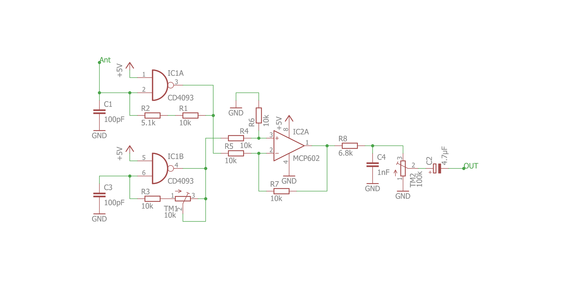
Reference Circuit Diagram
The circuit diagram used for the project is based on the reference diagram from the Instructables guide:
6. Main Components
| Component | Quantity | Purpose |
|---|---|---|
| CD4093 NAND Schmitt Trigger | 1 | Variable and reference oscillators |
| MCP602 dual op-amp | 1 | Analog signal processing |
100 pF capacitor (101) | 2 | Oscillator timing |
1 nF capacitor (102) | 1 | Signal filtering |
| 4.7 µF electrolytic capacitor | 1 | AC coupling |
| 10 kΩ resistor | 6 | Biasing, feedback and oscillator networks |
| 5.1 kΩ resistor | 1 | Variable oscillator timing |
| 6.8 kΩ resistor | 1 | Filter/output network |
| 10 kΩ potentiometer | 1 | Reference oscillator tuning |
| 100 kΩ potentiometer | 1 | Output/level adjustment |
| Metal rod / antenna | 1 | Capacitive sensing electrode |
100 nF capacitor (104) | 2 | IC power-supply decoupling |
| 5 V regulated supply | 1 | Circuit power |
7. Circuit Description
7.1 CD4093 Power
- Pin 14 → +5 V
- Pin 7 → GND
- A 100 nF (
104) decoupling capacitor is connected directly between pins 14 and 7.
7.2 Variable Oscillator
The first CD4093 gate is configured as an oscillator.
- Pin 1 → +5 V
- Pin 2 → sensing/timing node
- Pin 3 → oscillator output
- C1 = 100 pF (
101) from pin 2 to GND - R1 = 10 kΩ and R2 = 5.1 kΩ form the timing/feedback path
- The sensing antenna is connected to the timing node at pin 2.
7.3 Reference Oscillator
The second CD4093 gate forms the reference oscillator.
- Pin 5 → +5 V
- Pin 6 → reference timing node
- Pin 4 → reference oscillator output
- C3 = 100 pF (
101) from pin 6 to GND - R3 = 10 kΩ and TM1 = 10 kΩ form the timing/feedback path.
TM1 allows the reference oscillator to be adjusted to the desired operating point.
7.4 MCP602 Signal Processing
The MCP602 is powered using:
- Pin 8 → +5 V
- Pin 4 → GND
The oscillator signals are fed into the op-amp stage through resistor networks.
The output stage includes:
- R8 = 6.8 kΩ
- C4 = 1 nF (
102) - TM2 = 100 kΩ
- C2 = 4.7 µF
The 4.7 µF capacitor provides AC coupling to the audio output.
A second 100 nF (104) capacitor is placed directly between MCP602 pins 8 and 4 for supply decoupling.
8. Antenna / Sensing Electrode
The sensing antenna does not need to be a conventional RF antenna. A simple conductive metal object can be used as the sensing electrode. During prototype testing, a small metal rod approximately 9 cm long and 5 mm in diameter can be used.
CD4093 pin 2 ───────── metal sensing rod
The metal rod is not connected to 5 V or GND. It acts only as a capacitive sensing electrode.
Sensing range is affected by antenna length, diameter, surface area, surrounding metal objects, breadboard wiring, grounding, electrical noise, and distance from audio/speaker wiring.
9. Power Supply and Decoupling
The prototype uses a regulated 5 V DC supply.
CD4093:
Pin 14 (+5 V) ── 100 nF ── Pin 7 (GND)

MCP602:
Pin 8 (+5 V) ── 100 nF ── Pin 4 (GND)
A 4.7 µF electrolytic capacitor can also be connected across the main 5 V and GND rails. The 100 nF capacitors should be positioned as close as possible to the respective IC power pins.
10. Prototype Implementation
The first prototype was implemented on a breadboard using a regulated 5 V supply. The oscillator section was kept separate from the audio section as much as practical. The sensing electrode was positioned away from power rails, speaker cable, and other sources of electrical interference.
The prototype demonstrated that hand movement near the metal sensing electrode produces a measurable change in the audible output.
11. Testing and Observations
- The CD4093 and MCP602 received approximately 5 V supply voltage.
- The oscillator section generated a changing signal.
- A metal rod could be used as the sensing electrode.
- Bringing a hand closer to the electrode caused a noticeable pitch change.
- The circuit produced audible output through a powered speaker/audio system.
- Breadboard implementation introduced noticeable electrical noise and buzzing.
- The speaker and its FM antenna could interact with the sensing circuit and affect the observed response.
- Increasing antenna surface area can increase sensitivity, but can also increase susceptibility to interference.
The presence of a clear pitch change when the hand approaches the sensing electrode confirms that the basic capacitive proximity-sensing principle is functioning.
12. Sources of Noise and Mitigation
Possible sources include long breadboard jumper wires, poor power-supply decoupling, speaker/AUX cable coupling, nearby RF sources, large metal objects, breadboard parasitic capacitance, ground-loop effects, long antenna connections, and unstable power.
Recommended practices:
- Keep oscillator wiring short.
- Place 100 nF decoupling capacitors directly at the IC power pins.
- Keep the antenna away from power and audio wiring.
- Keep the speaker physically away from the sensing electrode.
- Use a stable regulated 5 V supply.
- Use a solid common ground.
- Move the circuit to a well-planned perfboard layout after breadboard validation.
13. Advantages
- Simple analog implementation
- No microcontroller required
- Low component count
- Low-cost components
- Contactless sensing
- Demonstrates practical capacitive sensing
- Immediate audible indication
- Suitable for educational experimentation
14. Limitations
- Sensitive to environmental electrical noise
- Breadboard parasitic capacitance affects operation
- Speaker and nearby RF sources can interfere with sensing
- Sensing range depends strongly on antenna geometry
- Analog tuning is required
- Current prototype does not provide a direct numerical distance measurement
- Environmental conditions can affect the response
15. Future Improvements
- Move the circuit from breadboard to perfboard.
- Improve grounding and power distribution.
- Optimize sensing electrode geometry.
- Add better RF/noise isolation.
- Design a dedicated enclosure.
- Develop a calibrated analog proximity indicator.
- Add an LED-based visual indication using additional analog circuitry.
- Improve the audio output stage.
- Experiment with different electrode shapes and sizes.
- Develop a compact PCB version.
16. Applications
- Contactless control interfaces
- Gesture-based electronics
- Interactive installations
- Educational demonstrations
- Electronic musical instruments
- Human-machine interfaces
- Touchless switches
- Experimental proximity sensing systems
17. Conclusion
The breadboard prototype demonstrates the fundamental sensing behavior, with hand movement producing a noticeable change in pitch. Although noise and environmental interference remain practical considerations, the project provides a useful platform for understanding capacitive sensing, oscillator design, analog signal processing, and contactless interaction.
18. References
- Instructables — “Make Your Own Simple Theremin” by GreatScottLab — reference for the oscillator-based circuit concept and component implementation. https://www.instructables.com/Make-Your-Own-Simple-Theremin/
- CD4093B CMOS Quad 2-Input NAND Schmitt Trigger Datasheet — IC operation and pin configuration.
- MCP602 CMOS Rail-to-Rail Input/Output Operational Amplifier Datasheet — op-amp operation and pin configuration.
- Capacitive sensing and proximity detection principles from analog electronics references.