An intresting title Part-2
6 / 2 / 2023

COURSEWORK
| deepak panwar | AUTHOR | ACTIVE |
6 / 2 / 2023
 Here we are only using one LED, so you can either remove one of the LEDs or add the logic for the other LED in the code. Code: [Click here][2] for the Arduino sketch which has the code for this Task.
 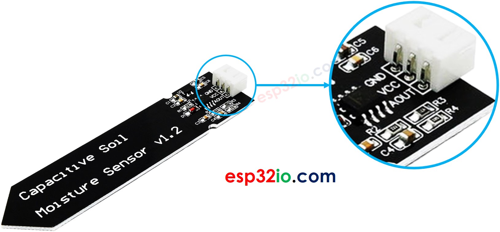 Working: The more is the water present in the soil the higher is the output of the AOUT pin. Connection:
 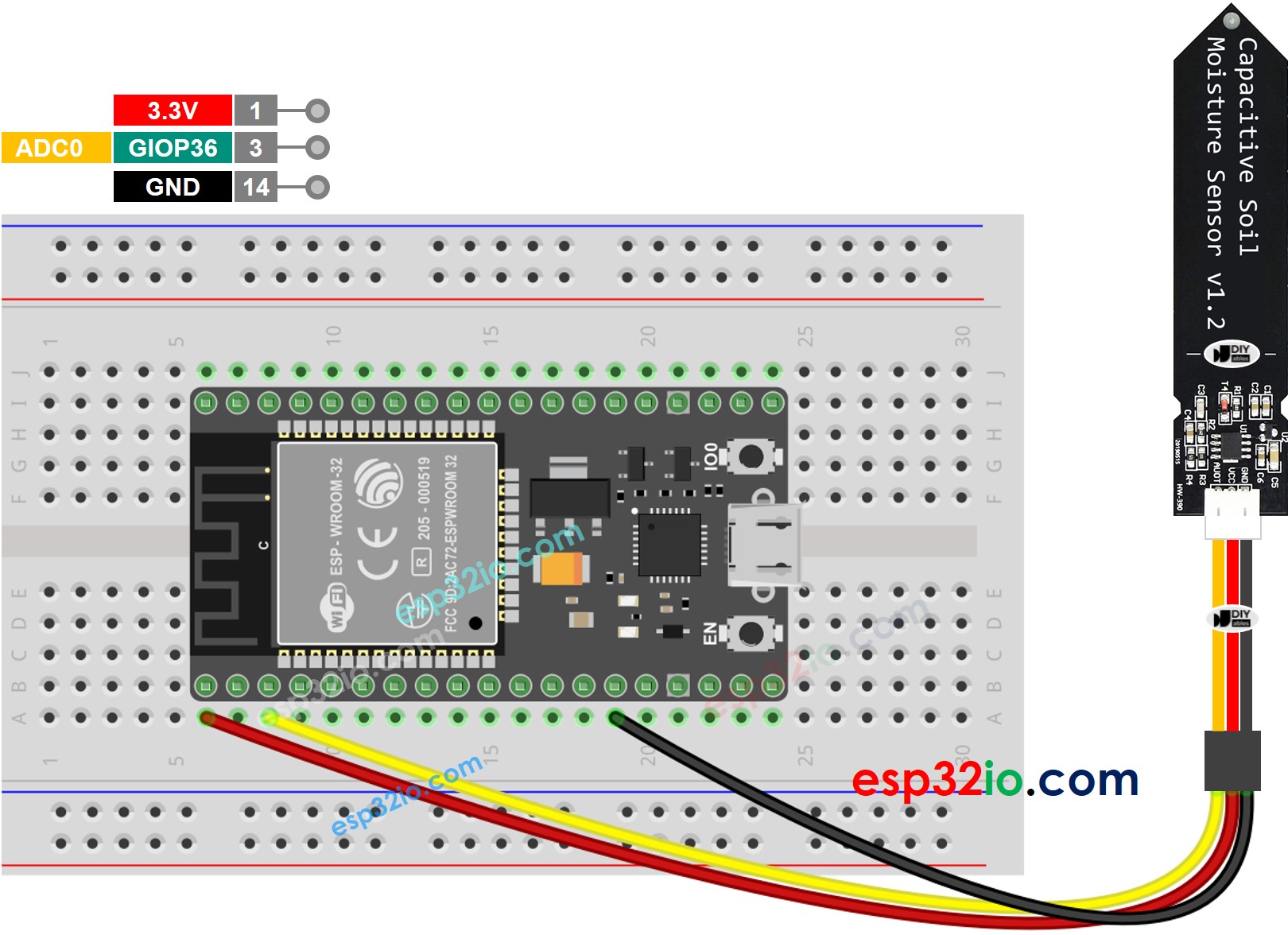 Code: [Click here][7], for the sketch. Procedure: 1. Make the connections as shows above. 2. Upload the sketch onto Esp32. 3. Go to serial monitor and check the values. Images:
  The sensor is integrated pulse oximetry and heart-rate monitor sensor solution. Working: The device has two LEDs, one emitting red light, another emitting infrared light. For pulse rate, only the infrared light is needed. Both the red light and infrared light is used to measure oxygen levels in the blood. When the heart pumps blood, there is an increase in oxygenated blood as a result of having more blood. As the heart relaxes, the volume of oxygenated blood also decreases. By knowing the time between the increase and decrease of oxygenated blood, the pulse rate is determined. It turns out, oxygenated blood absorbs more infrared light and passes more red light while deoxygenated blood absorbs red light and passes more infrared light. This is the main function of the MAX30100: it reads the absorption levels for both light sources and stored them in a buffer that can be read via I2C. Connection:
  The MAX30100 has I2C Pins. So connect its SDA pin to D21 & SCL pin to D22 of ESP32 Board. The power supply required by MAX30100 is 5V. So connect its VCC terminal to 5V of Arduino nano. Code: [Click here][10] for the arduino sketch. Upload the code to Esp32 and open the serial monitor. Images: