
COURSEWORK
Prathamesh's CL-CY-001 course work. Lv 1
| Prathamesh | AUTHOR | ACTIVE |
Prathamesh's CL-CY 001 Level 0 Report.
15 / 2 / 2026
Task 1: 3D Printing
3D printing is an additive manufacturing process where 3D objects are created layer by layer based on a digital model or code. So basically i tried to understand the entire workflow of the printer.
STL File: This is the standard file format for 3D printing. I downloaded one from Thingiverse.
Slicing: Before printing, the STL file is processed in slicer software like Cura converting it to G-CODE.
Process: After adjusting other settings like bed temperature , infill density and nozzle temperature, load the G-code via SD Card or USB and then begin the process. Once it's done let the build plate cool before removing anything.
Other Settings: Print speed, layer height, cooling fans, and support structures or pillars are important for print quality and accuracy.
Final outcome: 3D models were successfully prepared for printing by handling STL files, configuring slicing settings, and adjusting printer parameters.
Task 2: API
API stands for Application Programming Interface and it allows communication between frontend and backend. In this task, I built a Weather Application using data from openweathermap.org. I added the generated API key into the JavaScript file using VS Code and integrated it with the given reference code. I used a jQuery plugin to display the fetched weather data on the webpage. I initially faced issues while fetching the data and adjusted the style.css file to correct the output layout.
For this website I used HTML, CSS and JavaScript
Code
Final outcome: Weather data was successfully fetched from the API and displayed correctly on the website.
Task 3: Working with GitHub
In this task, I explored the given GitHub repository to understand its structure, commits, issues, pull requests, and GitHub Actions workflow. I forked the main branch to work on fixing an error in the code. Initially, I faced difficulty in understanding how forking and branch management works. After correcting the issue in my forked repository, I committed the changes. I then created and submitted a pull request to the main repository for review.
Link
Final outcome: The code error was fixed and a pull request was successfully submitted.
Task 4: Get familiar with the command line on ubuntu
Ubuntu was already installed as the default operating system on my laptop, so I started using it for regular tasks. I explored the interface and focused on working through the terminal. Since I was new to Linux, the commands were different from what I had used before. I practiced basic commands such as mkdir, cd, touch, cat, and chmod to understand file handling and permissions. With regular use, I became comfortable navigating and executing commands in the terminal.
The subtasks were:
- Create a folder named test.
- cd into that folder.
- Create a blank file without using any text editor.
- create 2600 folders in this folder where each folder is named like . For example, M90 or B56.
- concatenate two text files containing any random text and display them on the terminal.
| Task | Command |
|---|---|
| Create folder | mkdir test |
| Change directory | cd test |
| Create Blank File | touch empty |
| Create n folders | for i in {1....2600}; do mkdir M$i; done |
| Concatenate files | cat file1.txt file2.txt |
| Print Working Directory | pwd |
| Lists the contents in Directory | ls |
| Prints the given argument again | echo |
| Final outcome: I was able to use Ubuntu confidently and execute common Linux commands without difficulty. |
Task 6 : The Matrix Puzzle — Decode with NumPy & Reveal the Image
NumPy(Numerical Python):
- Designed for numerical and scientific computations
- Provides efficient data structures for managing large arrays and matrices
- Offers built-in functions for performing mathematical operations on data
- Enhances performance through optimized low-level implementations and vectorized operations, eliminating the need for explicit loops
Matplotlib:
- Enables users to generate different types of visualizations such as line graphs, bar charts, histograms, and more
- Assists in presenting numerical data visually, making patterns and trends easier to interpret and analyze
This task involved a scrambled matrix that needed to be rearranged using NumPy operations. After correctly reordering the matrix, the image was reconstructed and displayed using Matplotlib for visualization.
Operations used:
arr.shape= returns the number of rows and columns of the matrix.arr.size= returns the total number of elements peresent in the arary.arr.reshape()= changes the shape of an array.imshow()= displays data as an imageshow()= displays the plot
Final Outcome : A Smiley Face was successfully revealed after reconstructing and visualizing the reordered matrix.
TASK 7: Create a Portfolio Webpage
The portfolio website was created to present my profile in a clear and organized manner. It includes sections such as About Me, Academic Background, Skills, Projects, and Reach Out, providing a complete overview of my technical journey.
I used HTML, CSS and JS to develop my portfolio website.
GitHub Repository
Final outcome: A portfolio website was created to present the profile and showcase projects, skills, and work in a clear and organized manner.
Task 8: Writing Resource Article using Markdown
Markdown is an easy-to-use markup language . For this task, I created a technical resource article titled Impact of AI on Employment. The article explains how artificial intelligence and automation are affecting employment across industries, covering job displacement, impacted sectors, and the need for skill development. It also highlights the new opportunities created by AI, providing a balanced perspective on the future of work.This task improved my technical writing and content structuring skills, while helping me use Markdown effectively for clear and organized presentation.
Hyperlink : Impact of AI on Employment
Final outcome: A technical article titled Impact of AI on Employment was created using Markdown, explaining AI’s impact on employment, affected sectors, and emerging opportunities.
TASK 9: Tinkercad
Tinkercad is an online simulation platform used to design and test electronic circuits virtually. In this task, I explored the Tinkercad environment to understand how basic electronic components work together. I created a circuit using an ultrasonic sensor and a servo motor to build a simple radar-like object detection system. The components were connected virtually and the simulation was run to verify the output. I tested the sensor readings and servo movement to ensure proper working in the simulation.
Components used:
- Arduino UNO
- LED display
- Ultrasonic sensor
- Connecting wires
Ultrasonic sensor:
An ultrasonic sensor is an electronic device that measures distance using high-frequency sound waves. It emits ultrasonic pulses and calculates the distance by measuring the time taken for the echo to return, based on the speed of sound. It is widely used in obstacle detection, robotics, and parking assistance systems.
Final outcome: A radar-like object detection system was successfully simulated in Tinkercad.
Task 10: Speed Control of DC Motor
In this task, I used Arduino UNO, L298N motor driver, and a DC motor. The Arduino UNO generated a PWM signal where the duty cycle was controlled through the code. The L298N received a constant 12V supply from the power source. The PWM output from Arduino was connected to the ENA pin of the L298N. Based on the duty cycle, the L298N switched the motor supply ON and OFF rapidly, which changed the effective voltage applied to the motor. I assembled the circuit on a breadboard and corrected minor wiring mistakes during testing.
YouTube Link
Final outcome: The DC motor speed was successfully controlled and varied as required.
TASK 11: LED Toggle Using ESP32
In this task, I used ESP32, Arduino IDE, LED, 220Ω resistor, and connecting wires to toggle an LED using a webserver. The ESP32 was programmed to host a simple web server over WiFi. I connected the LED to a GPIO pin of the ESP32 through a 220Ω resistor. Using Arduino IDE, I wrote and uploaded the code to control the LED state through a browser. I corrected minor pin configuration errors during debugging and verified the LED response.
Connections are made as shown in the circuit diagram
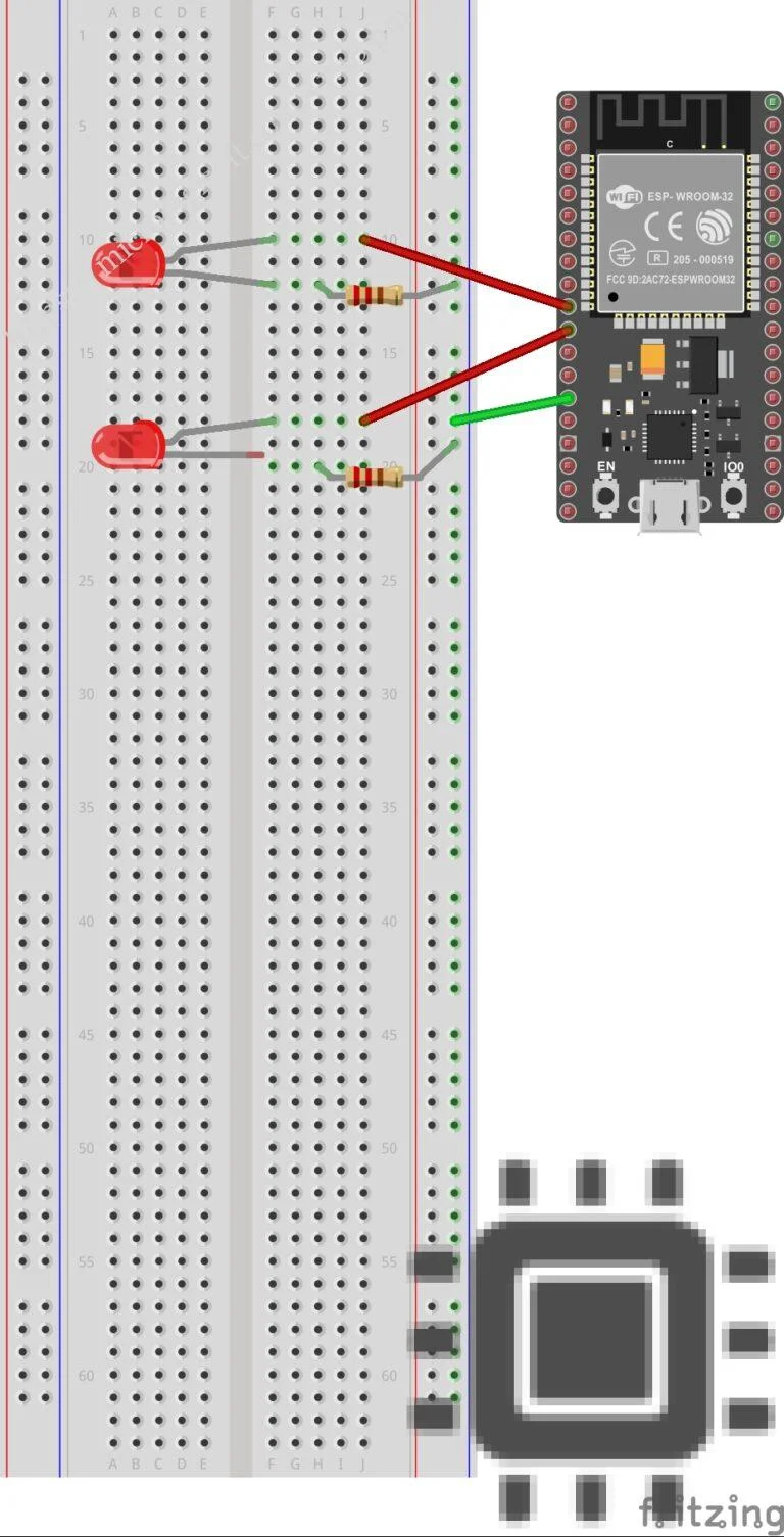 A wired connection between ESP32 and the Arduino IDE in the PC is established using a USB-A to micro USB cable. the required code is written in the IDE and is compiled and then uploaded into the ESP32 which is firmly connected to the other components through the GIPO pins. When the uploading of the code is completed an IP address will be generated in the IDE and in any browser you can enter that IP address and get access to the web server which toggles the LEDs.
Youtube Link
Final outcome: The LED was successfully toggled through a web interface using ESP32.
TASK 12: Soldering Prerequisites
I learned the basic prerequisites required before starting soldering work. I identified tools such as soldering iron, solder wire, flux, and safety equipment. I understood proper handling techniques and safety precautions. I practiced holding components and maintaining correct temperature control. I also observed common mistakes like cold joints and overheating.
Difference between Leaded and Lead-Free Solder
| Parameter | Leaded Solder | Lead-Free Solder |
|---|---|---|
| Composition | Tin (Sn) + Lead (Pb) | Tin (Sn) + Silver (Ag) + Copper (Cu) |
| Common Ratio | Sn63/Pb37 | Sn99/Ag0.3/Cu0.7 (varies) |
| Melting Point | 183°C | 217–220°C |
| Ideal Tip Temperature | 320–350°C | 350–380°C |
Final outcome: Basic soldering was performed successfully with proper joints and safety measures.
TASK 13: 555 Astable Multivibrator
In this task, a 555 timer IC was configured in astable mode to generate a continuous square wave output with a duty cycle of approximately 60%. I studied the working of the 555 timer in astable operation, where it switches continuously between HIGH and LOW states without external triggering. Resistors and a capacitor were connected according to the standard astable configuration. I calculated the time period and frequency using the required formulas before assembling the circuit. Minor wiring mistakes were corrected while verifying the output waveform.
| Components | Quantity |
|---|---|
| 555 timer IC | 1 |
| Resistors Ra = 10 KΩ | 1 |
| Resistors Rb = 20 KΩ | 1 |
| Capacitor C = 10 µF | 2 |
| Bread board | 1 |
| DC Power supply | 1 |
| Connecting wires | as per requirement |
The duty cycle of the astable multivibrator depends on the values of resistors Ra and Rb and capacitor C1, C2.
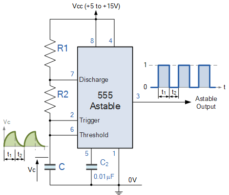
The circuit connections were made as shown in the above circuit diagram. The DC power supply was connected to the IC and then using the probes the output waveform was observed on the digital CRO screen by connecting the probes across the output and ground.
The waveform was an expected square wave.
Final outcome: The 555 timer successfully generated a continuous square wave in astable mode.
TASK 15: Active Participation:
I recently completed the Introduction to Generative AI course offered by Google Cloud Skill Boost, where I gained foundational knowledge about generative AI concepts, models, and real-world applications. Overall, it was a valuable learning experience that strengthened my understanding of emerging AI technologies.
Final outcome: Completed the Introduction to Generative AI course on Google Cloud Skill Boost, gaining foundational knowledge of generative AI concepts, models, and applications.
TASK 16: Datasheets Report Writing
L293D Motor Driver IC
I referred to the L293D motor driver datasheet and studied its pin configuration and working. I analyzed important specifications like voltage range, current rating, and internal H-bridge structure. I noted down functional diagrams and key electrical characteristics. I organized the collected information into a structured report format. The report focused only on technical specifications and usage details.
Hyperlink : L293D motor driver
Final outcome: A complete datasheet-based technical report on the L293D motor driver was prepared.
To continue reading my report (Task 18–19) click here