
30 / 3 / 2025
MECHANICAL DESIGN:
INTRODUCTORY MODULE
1. Fundamentals of CAD
I familiarized myself with the basic definitions of CAD, CAED, and related concepts using the file provided in the resources section of the MARVEL coursework page. After that, I applied for the Autodesk educational license.
I. Introduction to Engineering Drawing
Isometric & Orthographic Projections
Orthographic Drawing
Using the mini drafter, scale, and drawing pencils, I drew 7 Orthographic figures from the given drive folder. The following drive folder contains the drawings I made:
Link
Isometric Drawing
Using the mini drafter, scale, and drawing pencils, I drew 7 Isometric figures from the given drive folder. The following drive folder contains the drawings I made:
Link
2D Drawings in CAD
I used NX CAD to design my 2D sketches. Learning to create 2D sketches on NX CAD has helped me develop my design skills. I practiced using basic tools like lines, circles, and arcs while applying geometric and dimensional constraints for accuracy. Becoming comfortable with modifying sketches using trim, offset, and mirror functions improved my ability to create precise profiles, forming a strong foundation for 3D modeling.
.png)
.png)
.png)
.png)
.png)
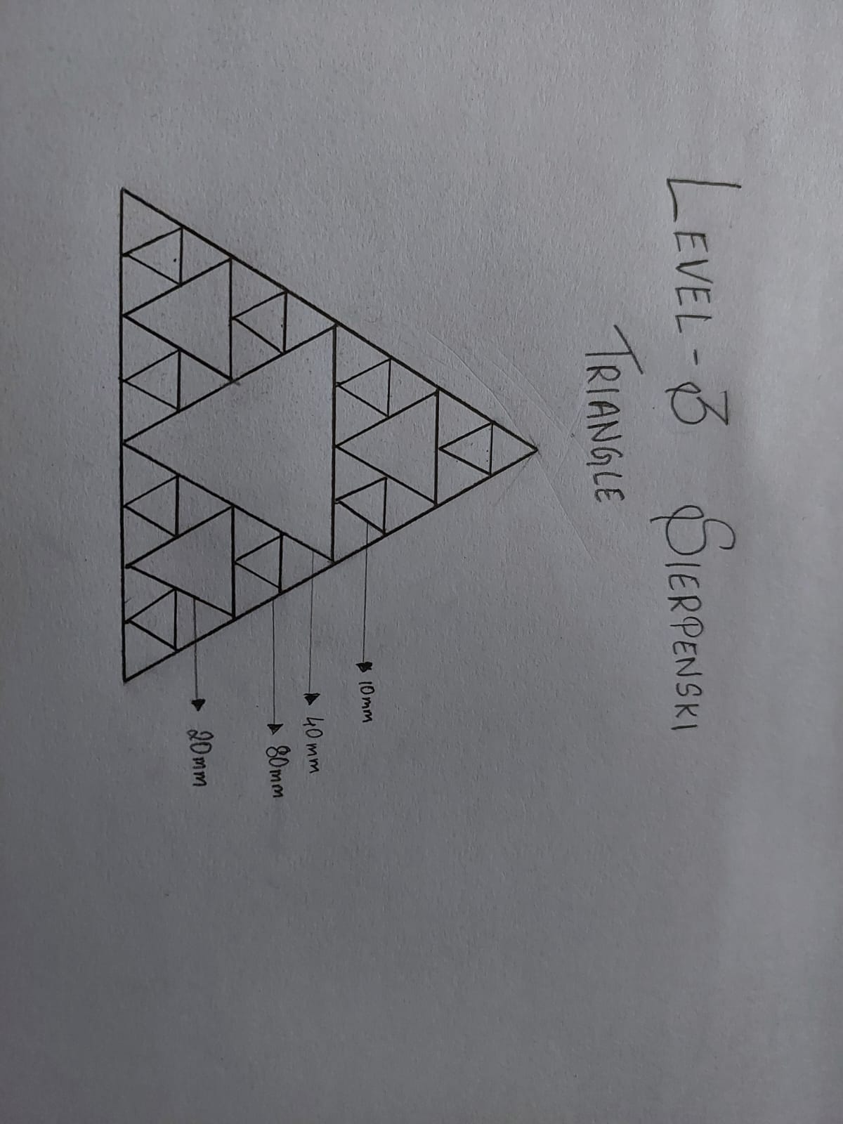
TASK: 2D Drafting
I explored the intricate geometry of Level 2 and Level 3 Sierpinski Triangles, refining my precision and design skills. Constructing the Level 2 triangle involved subdividing a large equilateral triangle into smaller sections and strategically removing the central triangle, revealing a striking fractal pattern. Advancing to the Level 3 triangle required repeating this process with greater complexity, resulting in a beautifully intricate and symmetrical design. This exercise deepened my understanding of recursive geometry and enhanced my ability to create detailed, mathematically inspired patterns.
.jpeg)
3D Drafting
Task 1: Allen key
An Allen key, also known as a hex key, is a small, L-shaped tool used to drive screws and bolts with hexagonal sockets. Its simple yet effective design allows for easy torque application and better grip, making it ideal for assembling machinery, furniture, and bicycles. To design an Allen key on NX CAD, I used the sweep tool. I first created a 2D sketch of the hexagonal profile, then defined the path for the L-shaped bend and fillet. Using the sweep tool, I extruded the hexagonal profile along the path, forming the complete Allen key shape with precision. This process helped me understand how to create complex shapes using path-based extrusion techniques.
.png)
Task 2: 3D machine parts
I created 3D models of three different machine parts on NX CAD, which helped me strengthen my modeling skills and understanding of mechanical components. I started by sketching the 2D profiles of each part, carefully applying dimensions and constraints for accuracy. Using extrusion, revolution, and cutting operations, I transformed these sketches into detailed 3D models. I also applied fillets, chamfers, and hole features to refine the designs and make them more realistic. This exercise enhanced my ability to visualize and construct complex parts, improving both my design precision and efficiency.
.png)
.png)
.png)
2. 3D Modelling
Solid Modelling
I designed a simple aerofoil for an HTOL aircraft using Fusion 360 by generating a NACA 2415 profile. To create the aerofoil, I used a plug-in to import the NACA coordinates from a .DAT file, which provided precise geometric data for the profile.
- 2 = Maximum camber as 2% of the chord length
- 4 = Position of maximum camber at 40% of the chord
- 15 = Maximum thickness of 15% of the chord
I refined the leading and trailing edges and ensured a smooth camber line to optimize the aerodynamic properties. This exercise helped me understand the fundamentals of aerofoil design, including the significance of camber, thickness distribution, and leading and trailing edge shaping..png)
.png)
Surface Modelling
I explored the concept of a toroidal propeller and its advantages in improving efficiency and reducing noise. A toroidal propeller features a looped or ring-like blade design, which helps minimize tip vortices, leading to quieter operation and increased thrust efficiency. To understand the design process better, I went through an introductory course on the Forms feature in Fusion 360, which allowed me to create complex curved surfaces and blade profiles.
.png)
Sheet Metal
I designed a post box for MARVEL using the Sheet Metal tools in Fusion 360. I used features like Flanges to build and shape the mailbox directly in 3D, adding bends and forms just like real sheet metal would be made. Fusion 360 automatically took care of important details like material thickness and bend radius, making sure the design could be manufactured realistically. This made it easy to create both a proper 3D model and a flat pattern for fabrication, streamlining the whole design process.
.png)
.png)
Organic Designing using Forms
I designed a hollow vase for MARVEL using the Forms feature in Fusion 360. . I started by creating a base and then extruded it and used the form features to shape the body of the vase. By adjusting the control points, I refined the curvature to achieve a smooth, aesthetically pleasing profile. This project helped me improve my surface modeling skills and better understand the flexibility of the Forms feature in creating organic shapes.
.png)
.png)
3. Prerequisite for Assembly in Fusion 360
A key prerequisite for assembly in Fusion 360 is understanding the difference between bodies and components. Bodies are individual shapes or solid parts within a single design file, used for creating and modifying geometry. In contrast, components are treated as separate, independent parts that can be assembled together. Components have their own origin, timeline, and relationships, making them suitable for creating moving assemblies. While bodies are used for basic part design, components are essential for defining motion, applying joints, and organizing complex assemblies in Fusion 360.
- Bodies – Individual shapes or solid parts within a single design file, used for creating and modifying geometry.
- Components – Separate, independent parts that can be assembled together.
4. Assembly and Animation
I designed a ratchet and pawl mechanism using As-Built Jointsto accurately define the motion and interaction between the components. I created the ratchet wheel with evenly spaced teeth and designed the pawl to engage with the teeth, allowing motion in one direction while preventing reverse movement. Using As-Built Joints, I defined a revolute joint for the ratchet wheel and a pivot joint for the pawl, ensuring smooth engagement and controlled motion. I also applied contact sets to simulate realistic interaction between the ratchet and pawl. This project helped me understand the importance of joint definitions and motion constraints in creating functional mechanical assemblies.
.png)
5. Spur Gear Design
I designed a spur gear based on the provided specifications using Fusion 360. . The design involved creating two gears to achieve a 2:1 gear ratio — an input gear with 20 teeth and an output gear with 40 teeth. I set the module (m) to 3 mm, which defines the size of the teeth, and applied a pressure angle (α) of 20 degrees to ensure smooth and efficient meshing of the gears. I used the Gear Generator add-in in Fusion 360 to create accurate tooth profiles and properly define the pitch circle and root circle diameters. This project helped me understand the fundamentals of gear design, including the importance of tooth geometry and gear meshing for effective power transmission.
.png)
6. Designing a Parametric Box
I designed a parametric box with threads in Fusion 360. , ensuring that the dimensions and features could be easily adjusted through parameter changes. The box was sized at 978 cm and included detailed internal and external threads for secure closure. I created multiple lid designs, including a hinge joint and a slide joint lid that slides smoothly into place along a guided track. After designing the components, I assembled them in Fusion 360, defining proper joint relationships. I then animated the assembly to demonstrate the opening and closing mechanism of both the hinge and slide joints, ensuring a precise and functional fit. This project enhanced my understanding of parametric design, joint mechanisms, and animation in Fusion 360.
##Hinge Joint
.png)
##Slide Joint
.png)
.png)
ELECTRONIC DESIGN:
Task 1: Engineer’s Swiss Army Knife
MATLAB OnRamp Course Report
The MATLAB OnRamp course, provided by MathWorks, taught me the basics of using MATLAB through simple and interactive lessons. I learned how to create variables, work with vectors and matrices, write scripts, use loops and conditions, import and clean data, and make plots. The course gave me a lot of practice by letting me solve small problems after each topic.
At the end of the course, I worked on a project using star spectrum data. The data were collected at wavelengths that were evenly spaced. I was given the starting wavelength (lambdaStart), the spacing between wavelengths (lambdaDelta), and the number of observations (nObs).
One task was to find the final wavelength (lambdaEnd) and create a vector (lambda) that listed all the wavelengths.
To solve it:
- I used the formula:
- I calculated
lambdaEndby plugging in the given values.
- I calculated
- Then, I made the
lambdavector fromlambdaStarttolambdaEnd, increasing bylambdaDeltaeach time.
This project helped me apply everything I had learned during the course — like creating variables, doing calculations, and working with vectors. Overall, the MATLAB OnRamp course gave me a strong start in using MATLAB for real-world problems.

Task 2: Convolution Countdown
To begin the task, I studied the basics of Digital Signal Processing (DSP), understanding that signals are functions carrying information and systems are processes that modify signals. I explored key mathematical tools like the Z-Transform, which represents discrete signals in the complex frequency domain, and the Fourier Transform, which analyzes signal frequency components. After building this theoretical foundation, I moved to MATLAB to practically apply the concepts by performing a simple linear convolution between two discrete signals, ( x = [1\ 2\ 3\ 4] ) and ( h = [1\ -1\ 2\ 0] ), using the conv() function. The resulting output, [1 1 3 5 2 8 0], confirmed my understanding of how convolution blends two signals, demonstrating the combined influence of both in a new output sequence. This exercise helped solidify my understanding of both the mathematical theory and its practical application in DSP.
.png)
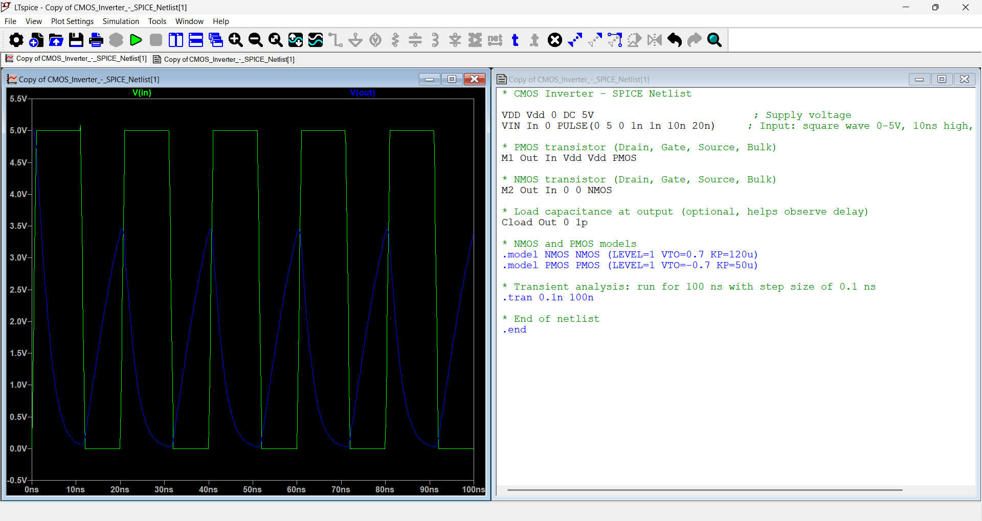
Task 3: SPICEy Code
SPICE code is a text-based language used to describe electronic circuits and their components to a SPICE simulator. SPICE, which stands for "Simulation Program with Integrated Circuit Emphasis", is a software tool that engineers use to model and simulate the behavior of electronic circuits.
- MOS
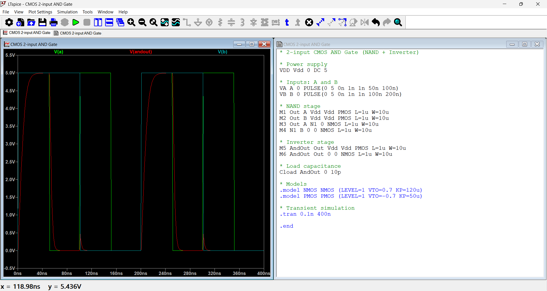
- AND
- OR
click for part 2 of the report