
4 / 6 / 2025
Task1: LTspice and KiCad
LTspice
It is a free circuit simulation software developed by analog devices. I designed an astable multivibrator 555 IC timer circuit. Designed it with the reference of resources given in marvel website. An astable 555 timer oscillates between high and low output states continously.
Expected output: A square wave at the pin (pin3) oscillating between 0V and ~Vcc, depending on component values.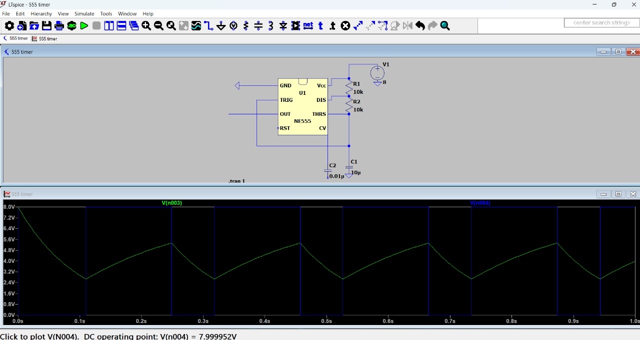
KiCad:
It is a free,open source software suite for Electronic Design Automation (EDA) used to design schematics and PCB's (Printed circuit boards). I familiarised with KiCad and designed a simple LED blinking circuit using a LED, resistor and a battery.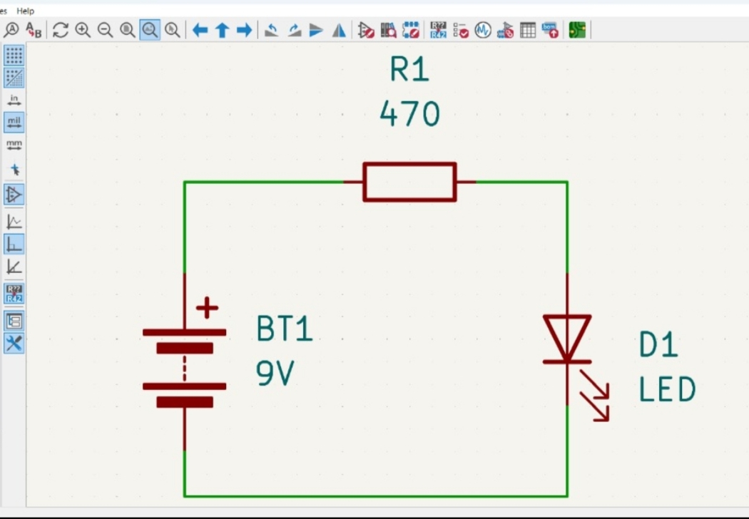

Task 2: Point Turn of a Vehicle with Ultrasonic Sensor
The HC-SR04 ultrasonic sensor module uses sonar technology to measure the distance of objects. It sends out ultrasonic waves and measures the time it takes for the waves to bounce back from an object. This time is then used to calculate the distance of the object.
Pins:
The HC-SR04 module has 4 pins:
- VCC (Power Pin): This pin is connected to the power supply (typically 5V)
- Trig (Trigger Pin): This pin is used to trigger the ultrasonic wave transmission
- Echo pin: This pin receives the echo signal after the ultrasonic wave bounces back from an object
- GND (Ground Pin): This pin is connected to the ground of the circuit
Components required:
- Arduino
- HC-SR04 Ultrasonic sensor
- Servo motor
- Buzzer or LED
Circuit Connections:
-
HC-SR04 Ultrasonic Sensor: - VCC to Arduino 5V - Trig to Arduino Digital Pin (e.g., Pin 9) - Echo to Arduino Digital Pin (e.g., Pin 10) - GND to Arduino GND
-
Servo Motor:
- VCC to Arduino 5V (or external power source if needed)
- GND to Arduino GND
- Signal to Arduino Digital Pin (e.g., Pin 11)
-
Buzzer or LED:
- Positive leg to Arduino Digital Pin (e.g., Pin 8 for Buzzer or LED)
- Negative leg to Arduino GND (through a resistor if using LED)
Here the HC-SR04 measures the distance to obstacles. When an onstacle is detected within a certain distance, a buzzer or LED indicated the obstacle.
The servo motor is used to change the direction by sweeping to the left or right to check for a clear path and then turning accordingly. Link for the video of working
Task3: Temperature and Humidity Detection
I designed a circuit to detect the temperature using LM35 Temperature sensor which is a low voltage, precision centigrade temperature sensor. It provides a voltage output that is linearly proportional to the temperature in celcius.
Components required::
- LM35 temperature sensor
- NPN transistor
- LED
- Resistor(1k and 220)
- Arduino
Connections
LM35
- Vcc to 5V on arduino
- GND to arduino
- Vout to A1(sensor pin)
Transistor pin
- Collector to one end of led ( through 220ohm)
- Emitter to GND
- Base to arduino pin 9
LED
- Anode(+) to collector of npn transistor
- Cathode(-) to GND through a 220ohm resistor

Output
- The LM35 sense the temperature and outputs an anlog voltage.
- Arduino reads this via analog pin A1 and converts it to celcius.
- If temperature exceeds the threshold temperature, it outputs high on pin 9
- This turns ON the npn transistor, allowing current to flow from collector to emmiter
- The LED lights up indicating that the threshold temperature has been crossed

DHT-11
is a basic digital tempperature and humidity sensor. The sensor comes pre-calibrated and requires no external circuit for measuring the temperature or humidity.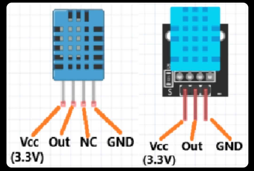
Connections
- Connect the Vcc to 5V, GND to GND, and DATA to a digital pin


Task8: BLDC Motor And Hall Effect Sensor
The Hall effect sensor is a magnetic sensor used to detect the presence and magnitude of a magnetic field. It operates based on the Hall Effect, discovered by Edwin Hall.
Working principles:
When a current-carrying conductor is placed in a magnetic field perpendicular to the current, a voltage (called Hall voltage) is generated across the conductor.
The main objective of this task is to measure the speed of BLDC motor and displaying it on the serial monitor using hall effect sensor.
Components required:
- A3144 Hall Effect sensor
- 5V DC fan (blower)
- Arduino UNO
- 10k resistor
- Breadboard
- Jumper wires

When the fan is kept closer to the sensor, the sensor reads the speed of the fan and the output is displayed on the serial monitor.
Task7: Solar Tracker
The solar tracker task aims to maximize electricity generation through sunlight by automatically orienting a solar panel towards the sun. This is achieved using light-sensitive sensors (LDRs) and a servo motor controlled by an Arduino Uno.
Components required
- Arduino
- Solar Panel
- Servo motor
- LDR(2) [Light dependent resistors that detect light intensity]
- 10K Resistors(2)
Circuit Connections
- Two LDRs detect light intensity on either side of the solar panel.
- The Arduino Uno compares the light intensity values and adjusts the servo motor to orient the solar panel towards the sun.Link for the video of working
Task8: Simple Electric Circuits Simulation on MATLAB
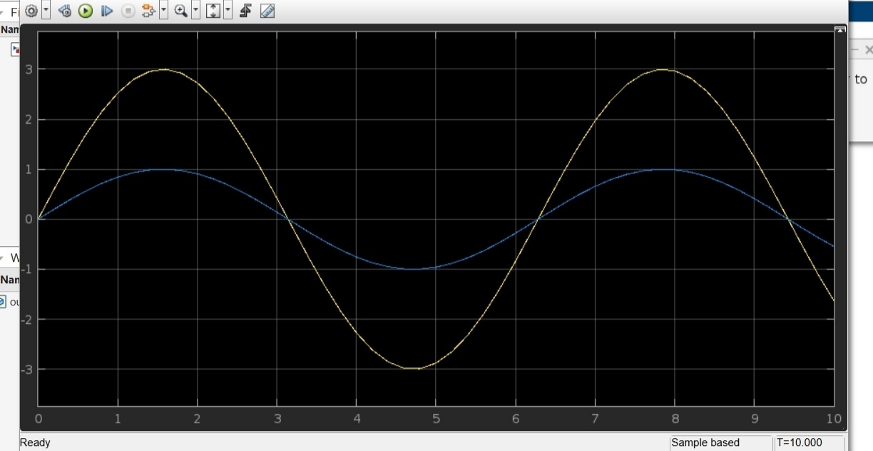
I designed an amplifier circuit using MATLAB. The circuit consists of a sine wave input signal with an amplitude 1V that is fed into an amplifier with a gain of 3.
Outcome: The sine wave input signal is amplified by the amplifier, resulting in an output signal that is three times the amplitude of the input signal.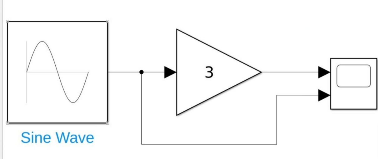
Task10: Auto Night Lamp Using LED for Electric Vehicles
This task demonstrates a simple light-sensitive LED circuit using an LDR and a BJT transistor. When light levels drop, the LDR's resistance increases.The increased resistance causes the transistor to switch on, allowing current to flow through the LED and the LED turns ON when the transistor is in the ON state.
Circuit Connections
- Connect LDR between Base (through 10K ohm to GND) and Vcc
- Cathode of LED to collector and Anode to Vcc through 220 ohm
- Emitter to GND
The led turns off when LDR senses light and it turns on automatically when it senses dark

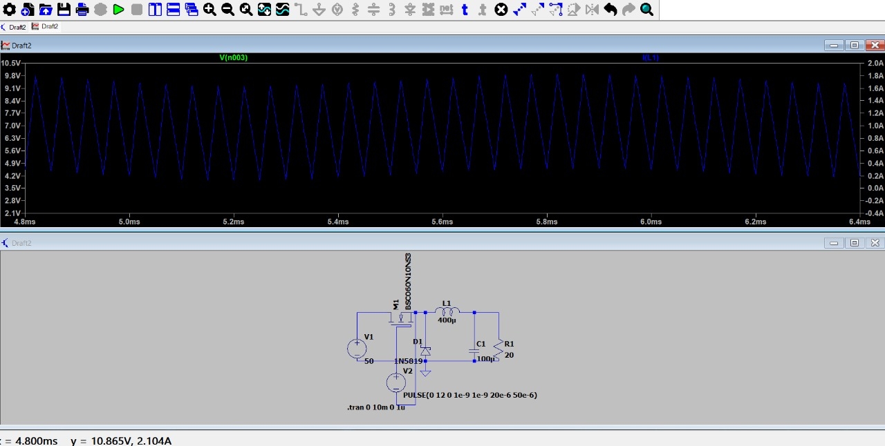
Task11: Buck converter on LTspice
A buck converter is a type of DC-DC converter that steps down a higher DC voltage to a lower DC voltage. It's like a voltage reducer that helps to efficiently power devices that require lower voltages.
Working
- The converter switches the input voltage on and off at a high frequency
- When the switch is on, the inductor stores energy from the input voltage
- When the switch is off, the stored energy is releases to the output, creating a lower DC voltage
Waveforms
- The output waveform(DC) is a relatively stable DC voltage.
- The inductor current waveform is typically triangular in shape indicating during the switch-on period, the inductor current increases, and during the switch-off period, it decreases.

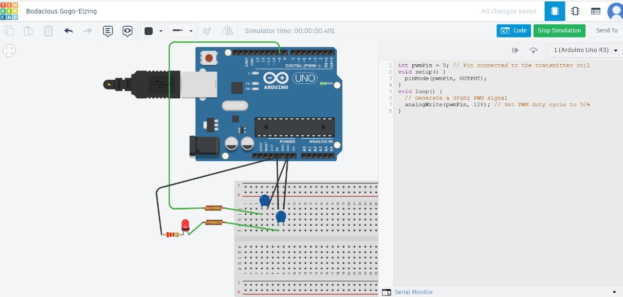
Task12: Wireless Charger Simulation on Tinkercad
Wireless power transfer (WPT) enables the transfer of electrical energy from a power source to a load without the need for physical connectors or wires. This technology is widely used in various applications, from charging smartphones to powering electric vehicles.
Components required
- Arduino Uno
- Inductor coils
- Capacitors
- LED
Working
- Wireless power transfer typically relies on electromagnetic fields to transfer energy between two coils—one acting as the transmitter and the other as the receiver.
- When the transmitter coil is powered, it creates a magnetic field that induces a current in the receiver coil, enabling power transfer.
Task13: Utilizing Transistors as Switches and Voltage Regulators
A transistor can be used as a switch to control the flow of current in a circuit. A transistor has three main terminals: Base, Collector, and Emitter. When a small input signal is applied to the Base, it controls the flow of current between the Collector and Emitter.
Switching Operation
- OFF State: When the Base voltage is low (or zero), the transistor is in the OFF state, and no current flows between the Collector and Emitter.
- ON State: When the Base voltage is high, the transistor is in the ON state, and current flows between the Collector and Emitter.
Components required
- NPN Transistor
- LED
- 220ohm 1k ohm resistors
- Arduino
Circuit Connections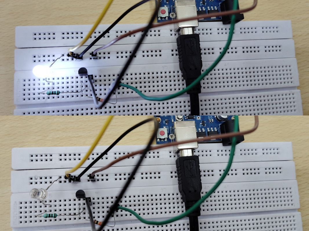
- Connect anode(+) of LED( through 220ohm) to 5V on arduino
- Connect Emitter of transistor to GND on arduino
- Connect Base of transistor via 1k ohm to digital pin2 on arduino. Working video

Voltage regulator
Voltage regulation is the process of maintaining a stable output voltage in a power supply or electronic circuit, despite changes in input voltage or load current. Ensures that devices connected to the power supply receive a stable voltage, preventing damage or malfunction.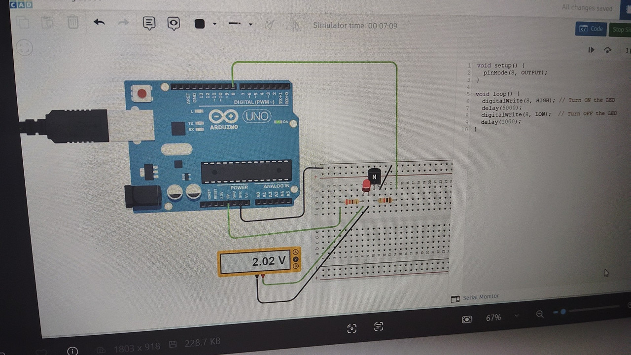
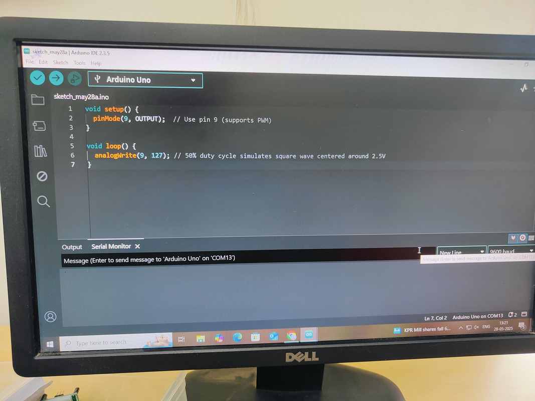
Task14: LED Brightness Control Using PWM and MOSFET
The brightness of an LED can be controlled by using an N-channel MOSFET through Pulse Width Modulation(PWM)
Components required:
- Arduino
- N-channel MOSFET
- LED
- Resistor(200 ohms)
Connections:
- Connect the anode of LED to the 5V on arduino
- Connect the cathode of the LED to the Drain of the N-channel MOSFET( through 220ohm)
- Connect the Source of the MOSFET to the GND of the arduino
- Connect Gate of the MOSFET to PWM-capable digital pin on the arduino(pin9)
Working
- The Arduino sends a PWM signal to the Gate of the MOSFET
- The MOSFET acts as a switch, controlling the current flow to the LED based on the PWM signal.
- By varying the duty cycle of the PWM signal,we can control the average voltage applied to the LED, thus adjusting its brightnes
- A higher duty cycle means the MOSFET is on for a longer period, allowing more current to flow to the LED, making it brighter
- A lower duty cycle means the MOSFET is on for a shorter period, resulting in less current to the LED, making it dimmer.
Working video

Task15: AC to DC Conversion and Observing Direct DC vs REctified DC
This task simulates an AC signal using Arduino's PWM output, converts it to DC using half-wave rectification, and filters the signal using a capacitor.
Components required
- Arduino
- Diode: Blocks the negative cycle of the AC signal
- Capacitor: Filters the rectified signal to produce a smoother DC output
- LED: Used to compare the brightness when powered by direct DC(battery) vs rectified DC output
Connections
- Arduino pin9 to Cathode of diode
- Anode of diode to one side of the capacitor and resistor + LED
- POsitive leg of capacitor to diode anode
- Negative leg of capacitor to GND on arduino
- LED cathode to GND
Outcome:
The LED glowed brighter when powered by direct DC (battery) compared to the filtered rectified DC output.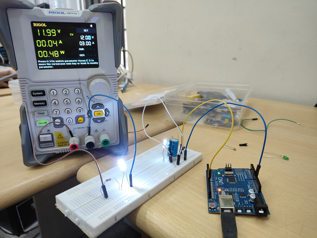
Task16: Generating an AC-Like Signal Using a 555 Timer and MOSFETs
This task involves using a 555 Timer IC to generate a square wave signal and driving two N-channel MOSFETs in a push-pull configuration to produce an AC-like signal.
Components Required:
- 555 Timer IC
- N-Channel MOSFETs
- Load(LED)
Working
- The 555 timer IC generates a square wave signal that alternates between high and low.
- The N-channel MOSFETs are connected in a push-pull configuration, where one mosfet connects to gnd and other pulls it to Vcc allowing efficient switching and amplification of the signal.
- Where the AC like signal can be used to drive an LED
- LED blinks alternatively for +Vcc and -Vcc Link for the video of working