
COURSEWORK
Thanuja's AI-ML-001 course work. Lv 1
| Thanuja G R | AUTHOR | ACTIVE |
3 / 10 / 2025
TASK 1: TINKERCAD
Objective: The objective of this task was to create a tinkercad account & to make a simple circuit to estimate the distance between the ultrasonic sensor and the object.
Components and Connections:
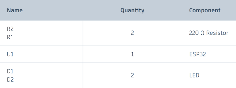
Below is the list of components used for the task:
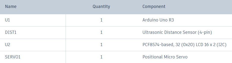
Connections :
a)Ultrasonic Sensor - Arduino UNO
VCC --> 5V
TRIG --> Pin 8
ECHO --> Pin 9
GND --> GND
b)LCD (16x2) 12C - Arduino UNO
VCC --> 5v
SDA --> Blank pin
SCL --> Blank pin\
GND --> GND
c)Servo Motor - Arduino UNO
Ground --> GND
Power --> 5V
Signal --> Pin 3
below image is the circuit made in the tinkercad:

Learnings and outcomes:
Familiarized with Arduino boards, including analog and digital pins, and the working of ultrasonic sensors. Ultrasonic refers to frequencies higher than 20 kHz, which are inaudible to humans. There are two parts to an ultrasonic sensor: a transmitter, which sends ultrasonic waves, and a receiver, which receives the reflected waves from an object. This allows the distance to be calculated using the speed of the waves emitted by the sensor and the time required for the receiver to detect the reflected waves, based on the formula.
d = s × t

click here to view my circuit.
TASK 2: API
Objective: Learn the working of an API and its applications. Using any API of your choice, build a user interface (web app, mobile app, etc), where you can make calls and then display the necessary information.
Learnings and outcomes: Developed a weather app that displays the weather for any location. To start, I obtained an API ID from OpenWeather API and then used HTML to build the web app.
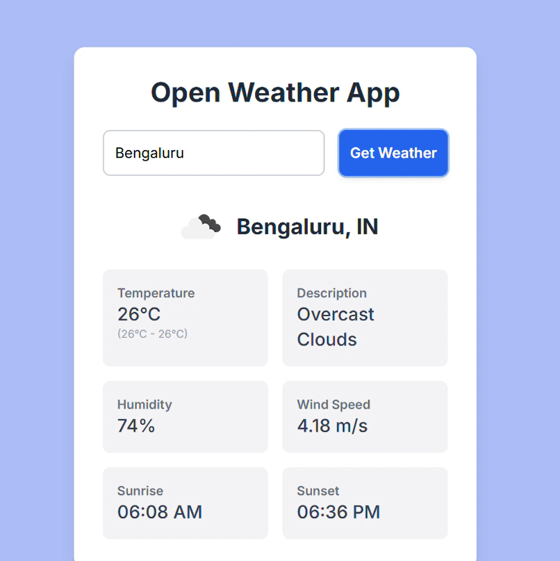
click here to view my app working.
TASK 3: WORKING WITH GITHUB
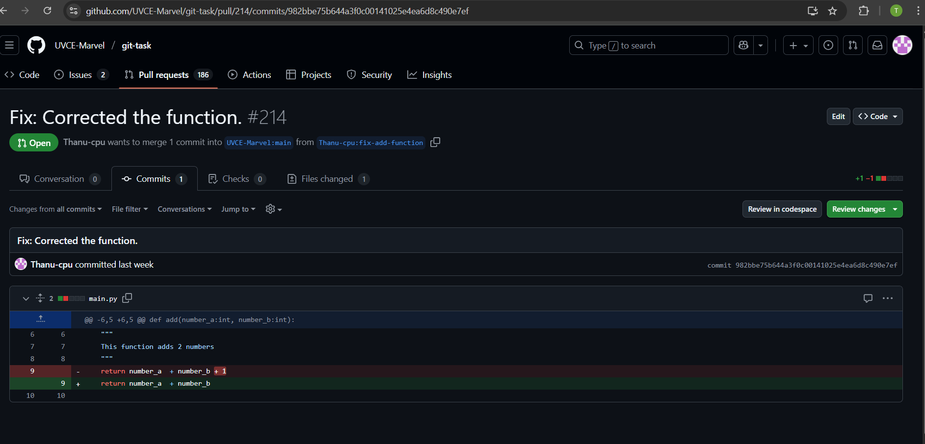
Objective: Familiarize yourself with GitHub integrated workflows (GitHub actions), Issues, and pull requests with this task. Given below is a git repository, go check it out and then perform the necessary tasks stated in the readme file as given in the MARVEL website.
Learnings and outcomes:
1)Firstly,i created my github account.
2)Learned how to create and delete repository.
3)Familiarize with github environment and learned how to fork and clone the repository, branch creation.
4)I forked the given repository into my repository and then cloned the repository, in order to complete the given specified marvel task.
TASK 4: COMMAND LINE ON UBUNTU
Objective: Get familiar with the command line on ubuntu.
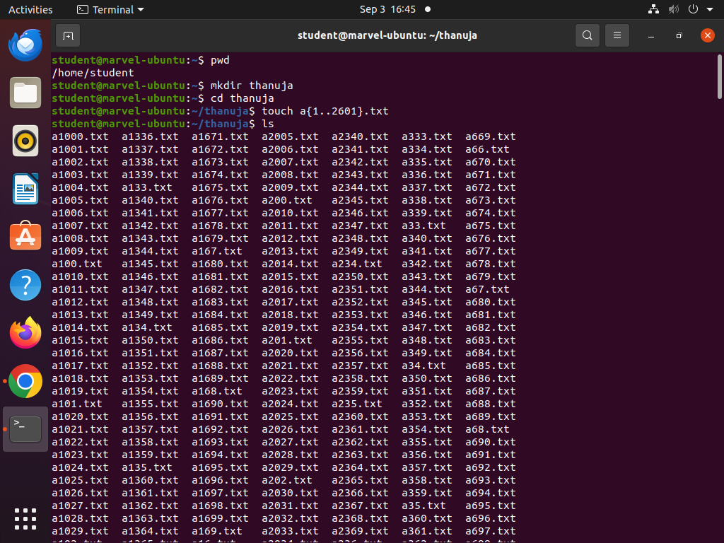
Learnings and outcomes: I learned basic Linux commands like,
- 'mkdir' to create folders.
- 'cd' to navigate directories.
- 'touch' to create blank files.
- 'ls' to list files.
- create multiple folders efficiently using loops.
- 'cat' to concatenate text files.
Using these basic commands, I completed the subtasks.
TASK 5: PORTFOLIO WEBPAGE
Objective: Create a website to showcase your portfolio - about yourself, interests, projects, social media profiles and more. It has to be responsive and also pushed to the git repository. CSS can be of your choice and any framework can be used.
Learnings and outcomes: I created my first portfolio,which showcasing my interests, skills, projects, and contact details using HTML and CSS. I pushed it to a Git repository, making it accessible to everyone and gained valuable knowledge about web development and the basics of HTML and CSS.
click here to view github repository.
click here to view my portfolio.
TASK 6: SPEED CONTROL OF DC MOTOR
Objective: Understand the control DC motors using the L298N motor driver and the Arduino board. Using an UNO and H-Bridge L298N motor driver, control the speed of a 5V motor.
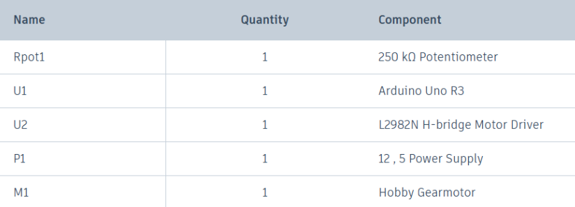
Components and Connections:
Below is the list of components used for the task:
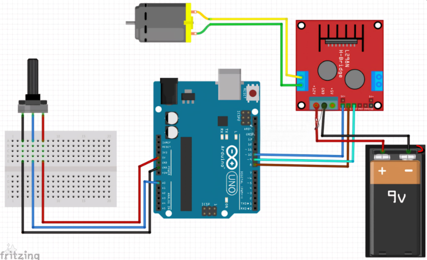
I reffered the below circuit for connections:
Learnings and outcomes:
L298N motor driver can control speed and direction of 2 motors at a time independently.In this task only 1 motor is used to demonstrate.
1)Based on H bridge principle.
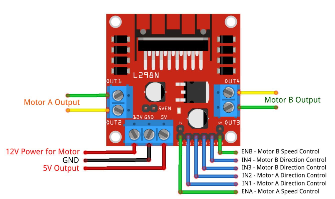
2)4 input pins(IN1,IN2,IN3,IN4) ,since we took 1 motor so IN1 & IN2 pins are used for connection.It has two input pins (IN1, IN2) to set the motor’s rotation direction.
3)An enable pin (ENA) to control speed through PWM signals from a microcontroller like Arduino.
4)By adjusting the PWM duty cycle on ENA, the motor’s speed can be varied.
5)The higher the duty cycle, the higher the average voltage applied to the DC motor, resulting in an increase in motor speed. The shorter the duty cycle, the lower the average voltage applied to the DC motor, resulting in a decrease in motor speed.
Here is the image of performing this task:
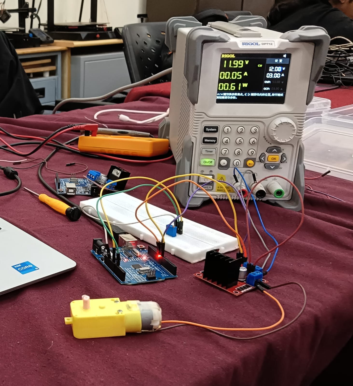 click here to view the video of performing task.
TASK 7: LED TOGGLE USING ESP32
Objective: Learn the working of an ESP32 and create a standalone web server with an ESP32 that controls the LED connected with ESP32 GPIOs. Use the arduino IDE to code and upload the program to the ESP32. Learn to configure the IDE to upload code to an ESP32.
Components and connections:
Below is the list of components used for the task:
Connections:
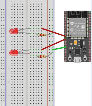
Referred below circuit along with the marvel website resource for the connections.
Learnings and outcomes:
Familiarized with ESP32 microcontroller.
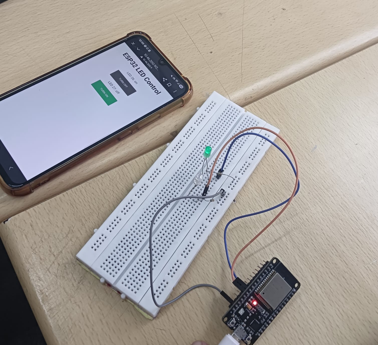
Feeded the code to microcontroller through Arduino IDE.After the succesful compilation,i received the IP address,pasted the address to browser & toggled the LED using same website.
 click here to view the video of LED Toggle.
TASK 8: K-MAP & DERIVING LOGIC GATES
Objective: Determine the Karnaugh map and make a burglar alarm using simple logic circuits. The buzzer or led blinks when certain conditions are met, you can use push buttons for the door and key.
Learnings and outcomes:
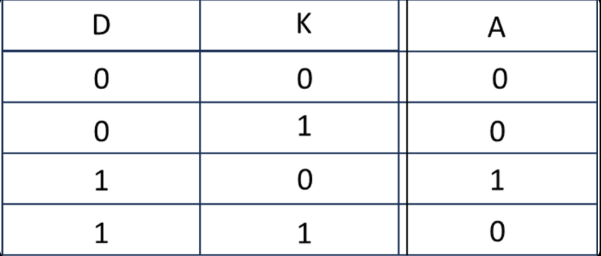
The task is to build a security alarm that alerts the user in case of unauthorized access, i.e., when the door opens in the absence of the key. Using CircuitVerse software, I built a circuit using an AND gate and a NOT gate along with an LED. Assumptions: Let's denote,
- Door by 'D', where an open door is represented by 1 and a closed door by 0.
- Key by 'K', where key insertion is represented by 1 and absence by 0.
Below is the truth table reffered to build the alarm,
K-map of the above truth table and the logic circuit followed,
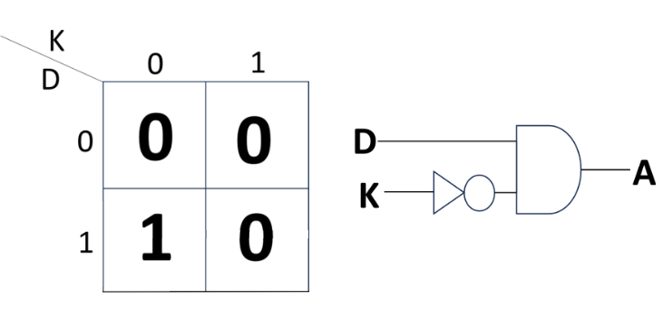 3)Output is denoted by 1.
When output is 1,LED will turn on.
Below is the logic circuit i built for security alarm,
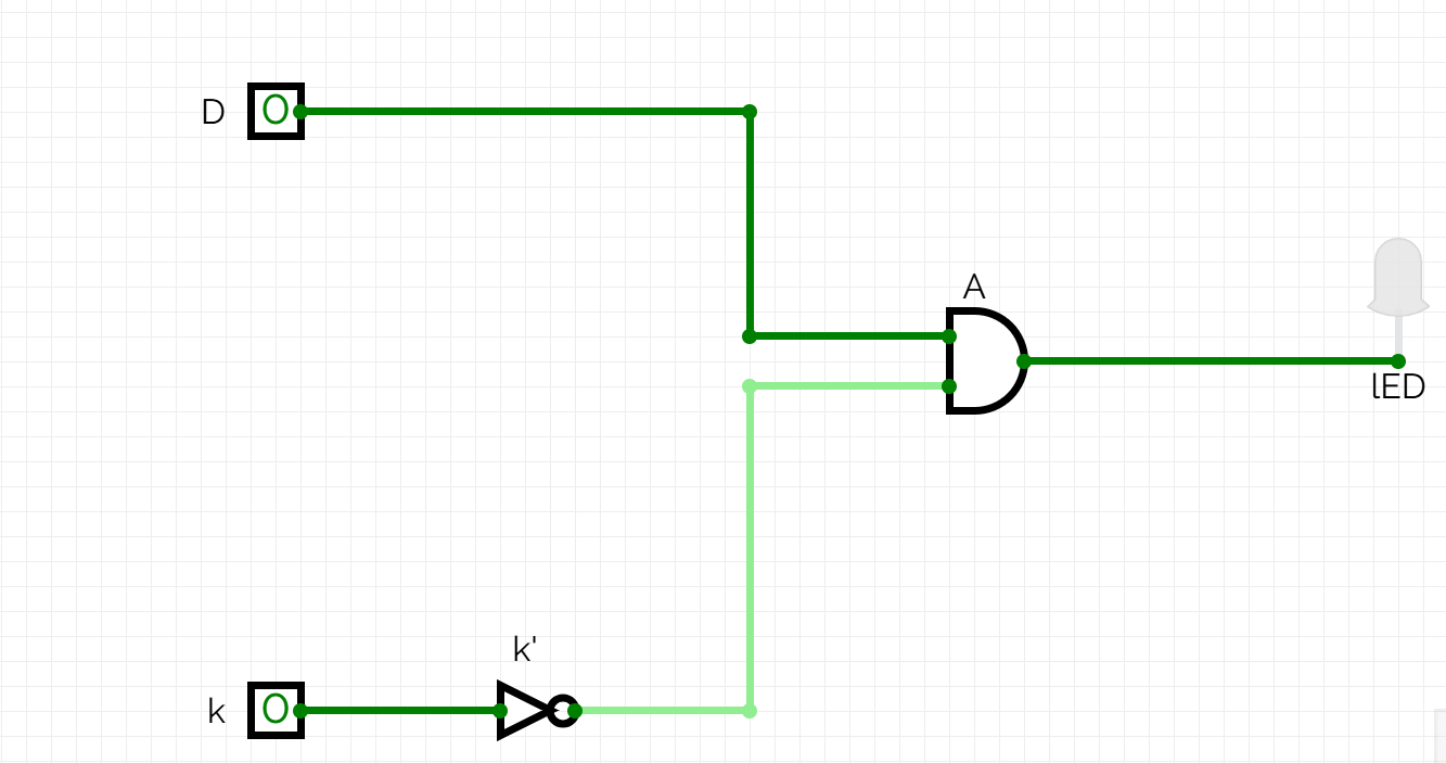
click here to view the working of security alarm circuit.
TASK 9: SOLDERING PREREQUISITES
Objectives: Learn about the soldering equipment and perform basic soldering on a perf board, for example a LED circuit.
Learnings and outcomes:
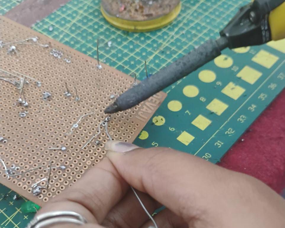
familiarized with soldering equipment like the solder, the soldering iron, soldering wick, flux etc.Also learned the technique of soldering and desoldering.
below is the image of soldering done in the lab by me:
TASK 10: 555 ASTABLE MULTIVIBRATOR
Objective: Design a 555 IC astable multivibrator with 60% duty cycle.
Components and Connections:
Components required:
1)555 IC Timer.
2)2 Capacitor (102)- 0.1nF.
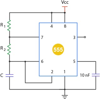
3)2 Resistor-> R1-10k ohm & R2-20k ohm.
Connections:
referred above circuit diagram for the connection:
Learnings and outcomes:
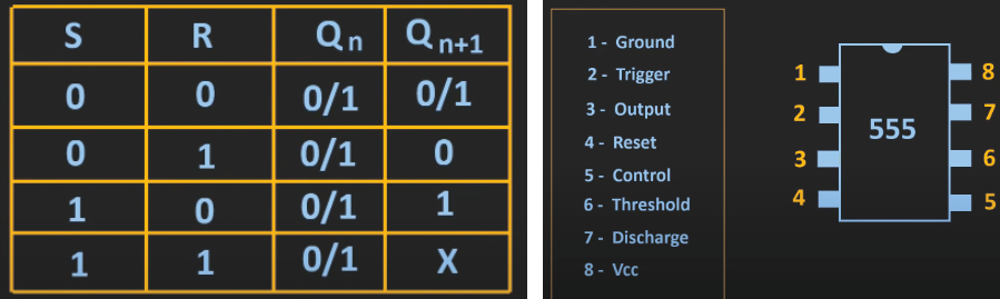
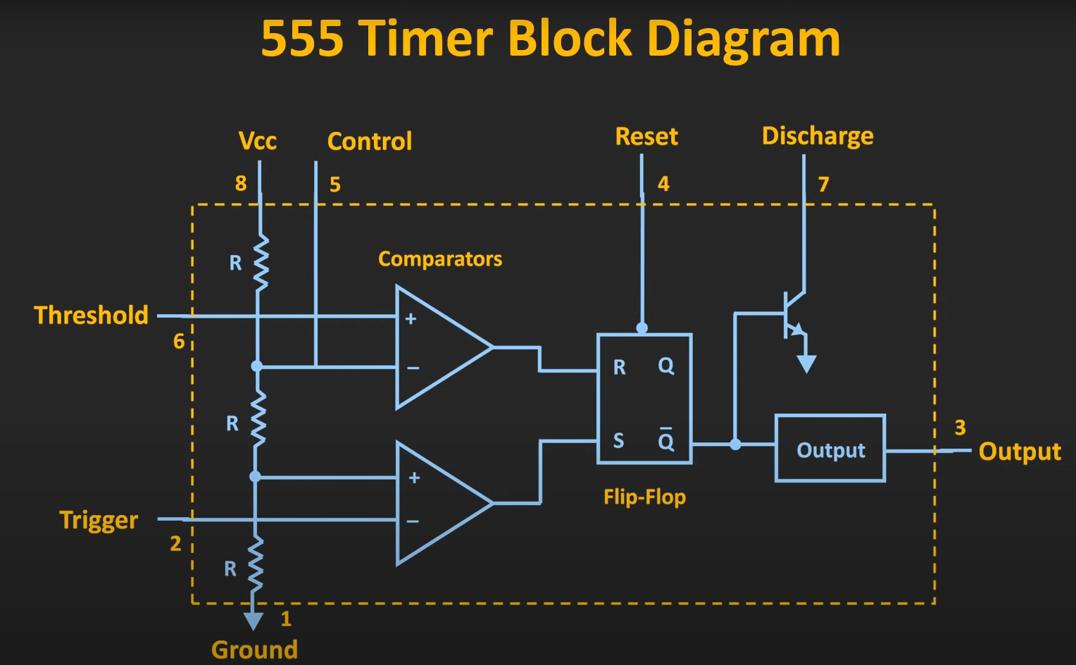
Familiarized with the pins of 555 IC timer,internal structure of the IC and types of multivibrator.Learned the working technique of timer,SR flip flop with truth table and it's applications.
On the basis of charging and discharging of capacitor, i get the knowledge about astable multivibrator.
image of 555IC with pin labelled,SR flipflop truthtable and internal circuit of the IC:
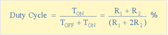
Here,the specified duty cycle is 60%.While conducting this task i got 59.21% of duty cycle.The formula of duty cycle is,
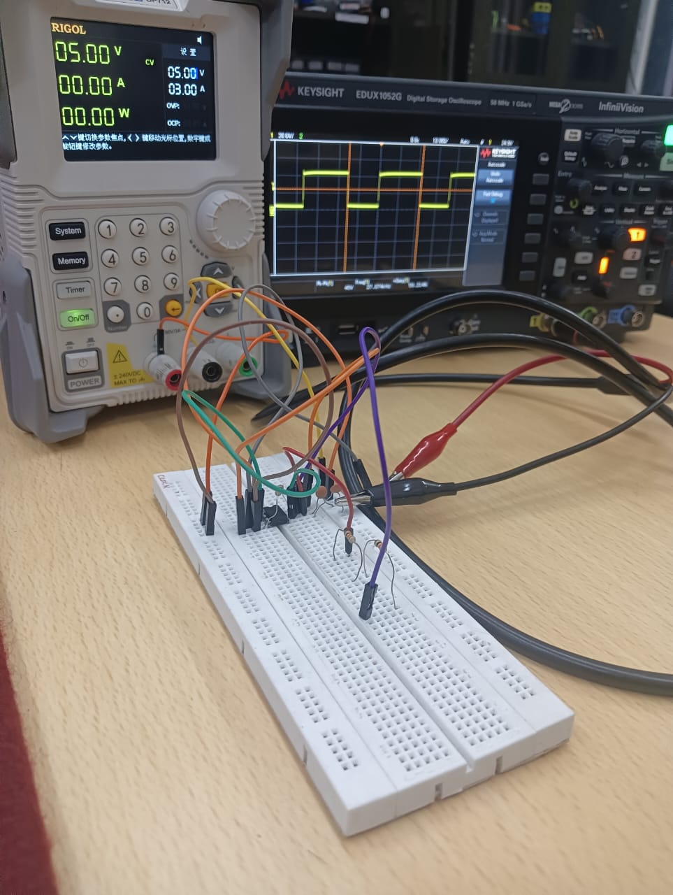
Glimpse of performing the task:
click here to view the complete task.
TASK 11: 3D PRINTING
Objective: Understand the working of a 3D printer, check out the online resources. Understand what's an STL file, and then learn to slice it. Learn about bed temperature, and other printer settings. Finally get an STL file from the internet, and slice it and put it for print.
Learnings and outcomes:
1)Nozzle Temperature:
For most PLA filaments, the ideal nozzle temperature is between 190°C and 220°C. Starting at 200°C is a good baseline, but you can adjust based on the specific brand and color for the best results.
2)Bed Temperature: While PLA can be printed on an unheated bed, using a heated bed set between 50°C and 60°C is highly recommended to improve first-layer adhesion and prevent the corners of your print from lifting (warping).
3)Printing Speed: A standard printing speed of 40-60 mm/s provides a great balance between print time and quality. For outer walls or highly detailed sections, slowing down to 20-30 mm/s can significantly improve the surface finish.
4)Cooling Fan: After the first one or two layers, your part cooling fan should be running at 100%. Proper cooling is essential for PLA to harden quickly, which allows for sharp details, clean bridges, and steep overhangs.
5)First Layer Settings: To ensure a successful print, make the first layer slightly slower and thicker than the rest. A common practice is to set the first layer speed to 20 mm/s and the layer height to 0.3 mm for excellent bed adhesion.
6)Post-Printing Procedures:
Once your print is complete, parts can be finished in several ways. PLA can be easily sanded for a smooth surface, primed and painted with acrylics, or joined together using cyanoacrylate (superglue) or a two-part epoxy.
NOTE: Due to some issue in 3D printer i wounldn't able to print the model.I'll print the model as soon as issue is fixed.
TASK 12: ACTIVE PARTICIPATION
Objective: Take part in any technical event, inter or intra college and submit the issued certificate of participation.
Outcome:
I participated in two events:
- KAGADA's poster track on mental health, where our team created and presented a poster.
- CodeFury, where our team choose the agricultural theme. We started building a web to connect markets and farmers for fair prices, but due to time constraints partially completed the backend development, while the frontend development was fully done.
 click here to continue the report!!