
COURSEWORK
Mihad's EV-RE-001 course work. Lv 1
| Mihad Fathime | AUTHOR | ACTIVE |
Mihad's EV-RE-001 course work.
10 / 4 / 2026
EV&RE LEVEL 0 REPORT
Task 1 — 3D Printing
Objective
Understand the working of a 3D printer, STL files, slicing, bed temperature, and printer settings. Slice an STL file and prepare it for printing.
Outcomes & Learnings
- PLA (Poly-Lactic Acid) is the most commonly used 3D printing material.
- Derived from renewable sources like corn and sugarcane.
- Breaks down faster than petroleum-based plastics.
Printer Settings
- Bed Temperature: 50°C – 60°C (recommended for PLA)
- Cooling: Set extruder fan speed to 100% for better detail
- Printing Speed: 55 mm/s or slower for best surface finish
Post Printing Procedures
- Joining parts: Cyanoacrylate glue or epoxy
- Painting: Most printed parts can be painted
- Sanding: Use progressively finer sandpaper carefully
Task 2 — API
Objective
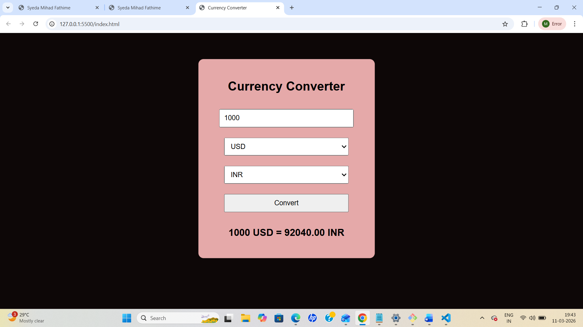
Learn API working and build a UI to display API data.
Outcomes & Learnings
-
Learned API working and applications
-
Built a Currency Converter Web App
-
Converts currency in real time
-
Technologies used:
- HTML
- CSS
- JavaScript
Task 3 — Working with GitHub
Objective
Learn GitHub workflows, issues, and pull requests.
Outcomes & Learnings
- Learned GitHub environment
- Created and deleted repositories
- Forked repository
- Cloned repository
- Made changes and pushed updates
Task 4 — Command Line on Ubuntu
Objectives
- Create folder named test
- Navigate into folder
- Create blank file
- List files
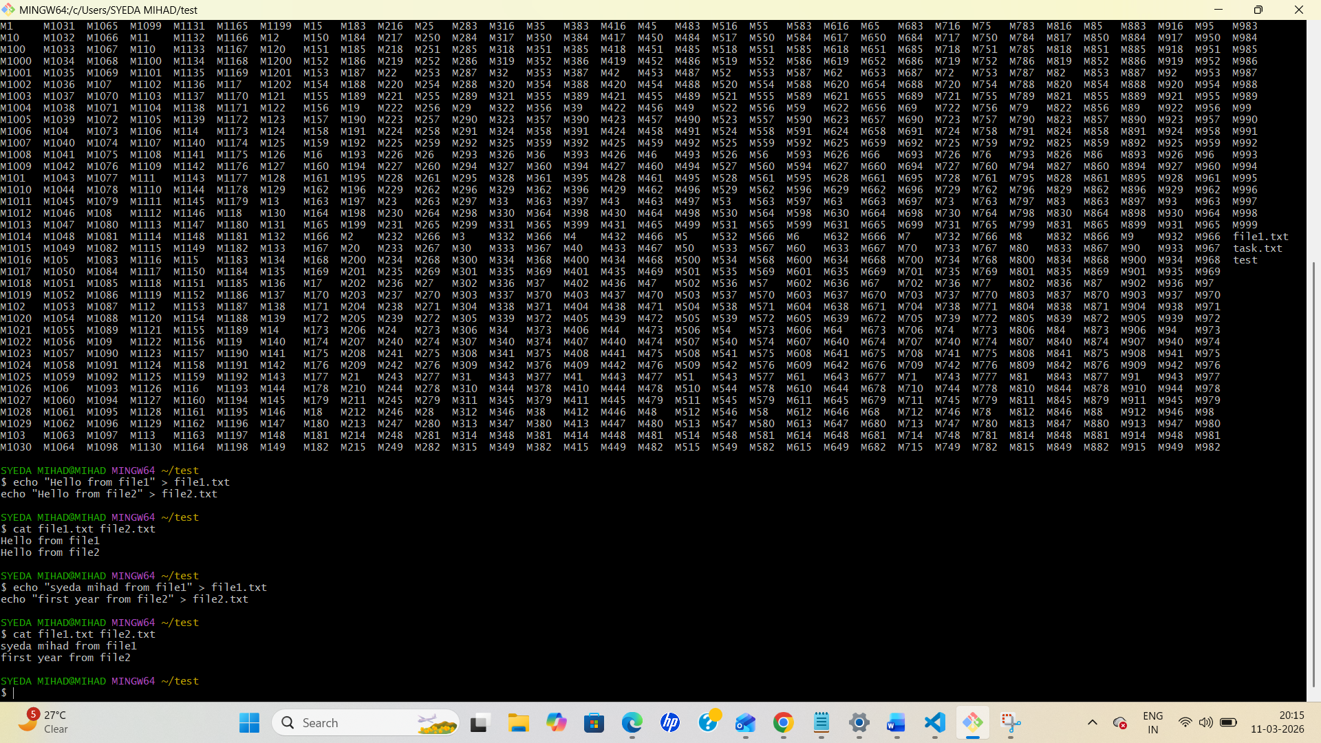
- Create 2600 folders
- Concatenate files
Steps
Create folder
mkdir test
Navigate into folder
cd test
Create blank file
touch blank.txt
List files
ls
Create 2600 folders
mkdir M{0001..2600}
Concatenate files
cat file1.txt file2.txt
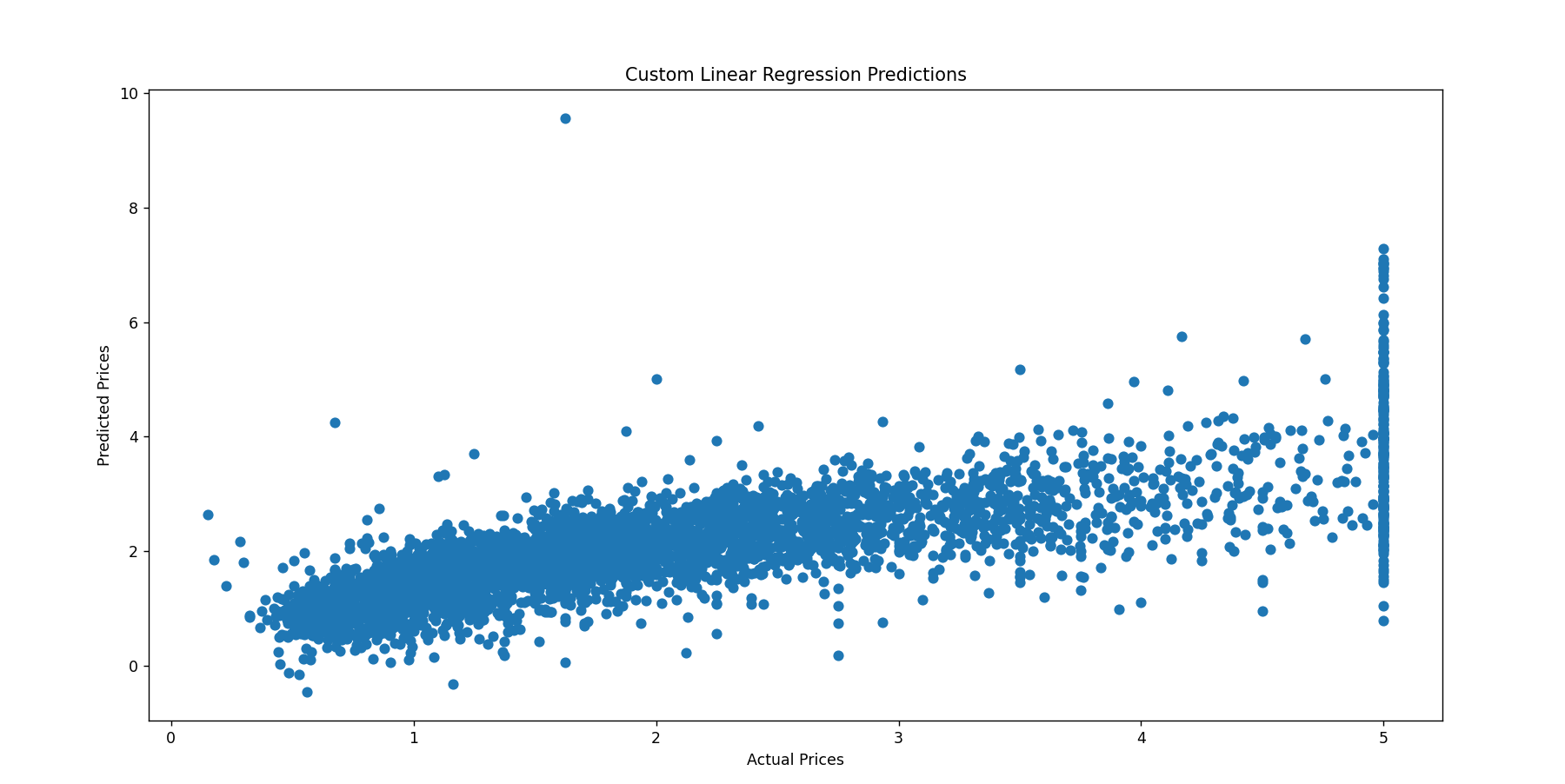
Task 5 — Linear Regression from Scratch
Learning Outcomes
- Understood gradient descent
- Learned weight optimization
- Learned feature scaling
- Implemented linear regression model
Task 6 — Matrix Puzzle using NumPy
Objectives
- Download scrambled matrix
- Manipulate using NumPy
- Reveal image using Matplotlib
Steps
- Load matrix into NumPy array
- Check shape using
array.shape - Reshape matrix
- Apply transformations (
rot90,flip) - Plot using
imshow()

Task 7 — Portfolio Webpage
Objective
Create responsive portfolio website and upload to GitHub.
Outcomes & Learnings
- Learned HTML and CSS
- Basic JavaScript
- Added social links
- Contact form implemented Click here to view my website
Task 8 — Writing Resource Article Using Markdown
Outcomes & Learnings
- Wrote technical article
- Added images
- Learned tables
- Used sub-headings
- I wrote a resource article on the sensors used in smart devices which built my understanding on various sensors used .
- I also linked few images from Wikipedia to it . it built my understanding of how articles can be written using Markdown.I also learnt how to add tables and sub-headings in the Markdown
Task 9 — Tinkercad
Objective:
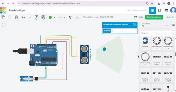
The objective of this task was to create a tinkercad account & to make a simple circuit to estimate the distance between the ultrasonic sensor and the object.
Methodology
For this project we’ll need the following components: The connections made are as follows:
| Component | Arduino UNO Pin |
|---|---|
| Ultrasonic Sensor | VCC, TRIG, ECHO, GND |
| VCC | 5V |
| TRIG | Pin 8 |
| ECHO | Pin 9 |
| GND | GND |
| Servo Motor | Ground, Power, Signal |
| Ground | GND |
| Power | 5V |
| Signal | Pin 3 |
Note: Here the Pins 8, 9 & 3 are Digital PWM pins on the Arduino.
Outcomes & Learnings
- Working of the Ultrasonic sensor: The term "ultrasonic" refers to frequencies higher than 20 kHz, which are inaudible to humans because they exceed the upper limit of the human hearing range. Ultrasonic sensors typically have two cylindrical components protruding outward: a transmitter (T) and a receiver (R). The transmitter emits ultrasonic sound waves, which interact with an object in front of the sensor and reflect back to the receiver. The distance between the ultrasonic sensor and the object is calculated based on the time it takes for the reflected ultrasonic wave to reach the receiver. The formula used for this calculation is: 𝑑=𝑠⋅𝑡 where:
- • 𝑑 = Distance between the object and the ultrasonic sensor
- • s = Speed of the ultrasonic wave signal
- • t = Time taken by the reflected signal to reach the receiver To increase the range and coverage area of the ultrasonic sensor, it can be mounted on a servo motor, allowing it to rotate. This setup enables the sensor to act as a radar, scanning a wider area and providing better distance measurements.
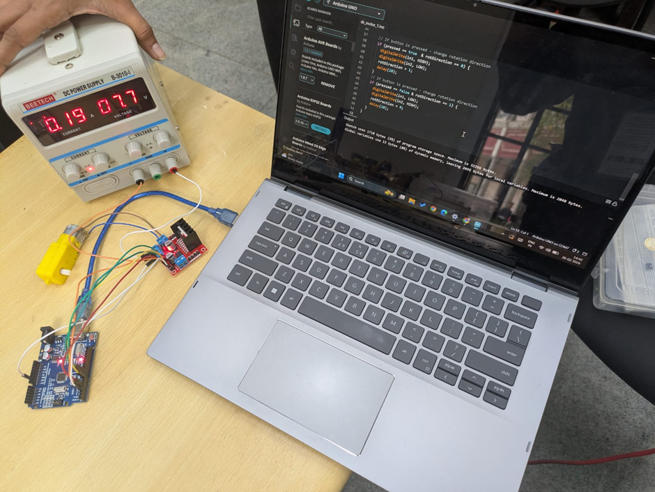
Task 10 — Speed Control of DC Motor
Components Used
- DC Motor
- L298N Motor Driver
- Arduino UNO
- Battery
Methodology
- I first made the connections in tinkercad and later than performed using the components in lab.
- The components’ used were: DC motor, L298N motor driver(H-bridge), Arduino Uno, 5V BATTERY,
| L298N Motor Driver | Arduino/Power Connection |
|---|---|
| ENA | Pin 10 (Arduino UNO) |
| IN1 | Pin 8 (Arduino UNO) |
| IN2 | Pin 9 (Arduino UNO) |
| GND | Negative terminal (9V supply) |
| +12V | Positive terminal (9V supply) |
| Output 1 | Terminal 1 (DC motor) |
| Output 2 | Terminal 2 (DC motor) |
- Through this task I learned the pins and workings of L289N Motor driver pin along with the functions of motor and power supply. Through the interference of Arduino uno I was able to manage the speed of DC motor by varying the voltage. Although I faced a challenge while uploading the code to Arduino uno but it was later resolved by changing the hardware. Here is the glimpse of me performing it :
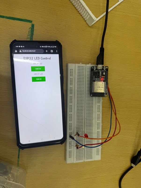
Task 11 — LED Toggle Using ESP32
Objective
Create standalone web server using ESP32.
Outcomes & Learnings
- Learned ESP32 GPIO control
- Configured WiFi credentials
- Controlled LEDs using web interface
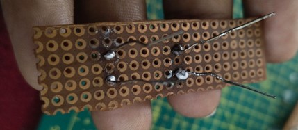
Task 12 — Soldering Prerequisite
Learning Outcome
- Learned soldering basics
- Soldered LED on perf board
- Practiced desoldering
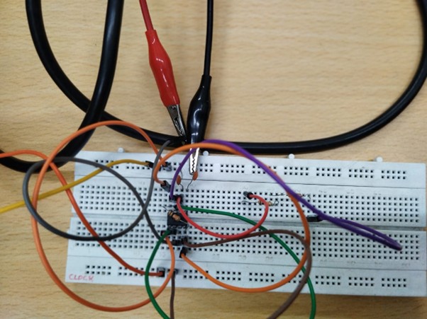
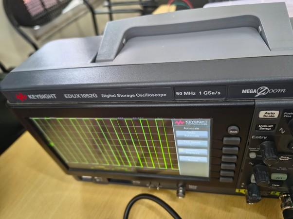
Task 13 — 555 Timer Astable Multivibrator
Objective
Design 555 timer with 60% duty cycle.
Components required
NE555 IC, resistors (10 kilo ohms & 5 K ohm ), capacitor (0.01 µF), breadboard, DC supply, connecting wires, DSO.
Theory
In astable mode, the 555 timer produces a continuous square wave.
- Duty Cycle=(R_A+R_B)/(R_A+2R_B )
Working process :
Connect the 555 timer in astable mode on the breadboard.
Connect R_Abetween Vcc and pin 7, and R_Bbetween pin 7 and pins 2 & 6.
Connect capacitor between pins 2 & 6 and ground.
Apply DC supply.
Connect the DSO probe to pin 3 and observe the waveform.
Result
The astable multivibrator using 555 timer was implemented successfully and a square wave with approximately 59.5% duty cycle was achieved which is close to required 60% duty cycle .
- Here are the glimpse of it :
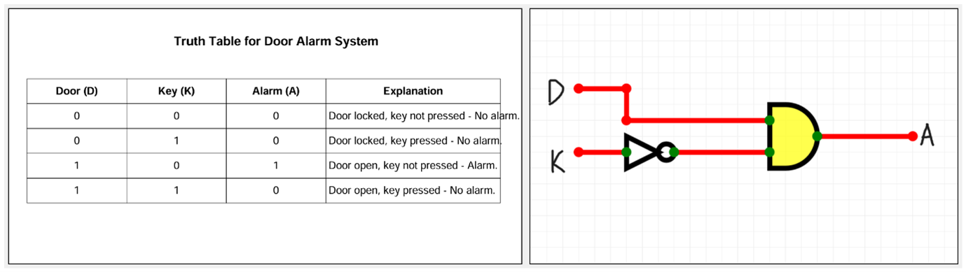
Task 14 — Karnaugh Maps
Objective
Design burglar alarm system using K-map.
KEY CONCEPT:
It helps in minimizing logical expressions by visually organizing combinations of inputs and outputs. We considered 4 cases based on the following inputs: -Door (D): -Locked → D = 0 -Open → D = 1 -Key (K): -Not Pressed → K = 0 -Pressed → K = 1
LEARNING OUTCOME:
Since this is a burglar alarm, it should start ringing in case of un-authorised access i.e. when the door opens in the absence of the key. So, let’s make the following assumptions: We denote state of: • Door by, ‘D’. Open door is denoted by 1, closed door is denoted by 0. • Key by, ‘K’. If key is NOT put on the door it’s denoted by 0 and if key is put on the door it’s denoted by 1. • The burglar alarm is denoted by, ‘A’ where 1 means the alarm is activated and 0 means the alarm is off.
Karnaugh Map
| D \ K | 0 | 1 |
|---|---|---|
| 0 | 0 | 0 |
| 1 | 1 | 0 |
Simplified Expression:
A = D K'
- K-map obtained from the given truth table is:
Task 15 — Active Participation
- Participated in coding hackathon
- Learned prompt coding
- Enrolled in NPTEL Data Science course
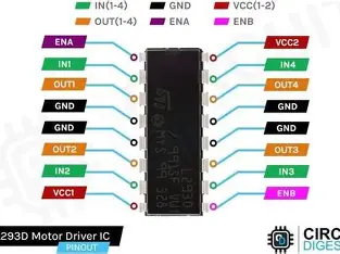
Task 16 — Datasheet Report (L293D)
- Datasheet Report: L293D Quadruple Half-H Driver
Internal Architecture: The H-Bridge
The core of the L293D is the H-Bridge configuration. An H-Bridge is an electronic circuit that allows a voltage to be applied across a load in either direction. The L293D is a high-voltage, high-current, 4-channel driver designed to provide bidirectional drive currents of up to 600mA at voltages from 4.5V to 36V. It is commonly used to drive inductive loads such as relays, solenoids, DC motors, and bipolar stepping motors.
2. Internal Architecture: The H-Bridge
The core of the L293D is the H-Bridge configuration. An H-Bridge is an electronic circuit that allows a voltage to be applied across a load in either direction. • How it works: By closing specific pairs of switches (e.g., S1 and S4), current flows through the motor in one direction. By closing the opposite pair (S2 and S3), the current reverses, changing the motor's rotation. • Protection: The "D" in L293D stands for the internal Clamping Diodes. These protect the IC from "back EMF" (voltage spikes) generated when a motor starts or stops.
3. Pulse Width Modulation (PWM) & Speed Control
While the H-Bridge handles direction, PWM handles speed. • The Logic: Instead of providing a steady 5V, the L293D can be fed a pulsed signal. • Duty Cycle: By varying the "on-time" versus "off-time" (the Duty Cycle), the average voltage delivered to the motor changes. • Implementation: In the L293D, the Enable pins (Pin 1 and Pin 9) are usually connected to a PWM-capable microcontroller pin to throttle the motor speed.
4. Pin Configuration & IC Specifications
The L293D is a 16-pin Dual In-line Package (DIP).
| Feature | Specification |
|---|---|
| Supply Voltage V | 4.5–7V |
| Output Supply Voltage | up to 36V (Motors) |
| Output Current: 600 mA per channel | |
| Peak Output Current | 1.2A (Non-repetitive) |
| Thermal Protection | Internal over-temperature shutdown |
5. Functional Logic Table
For a single motor connected to Output 1 and Output 2:
| Enable 1,2 | Input 1 | Input 2 | Result |
|---|---|---|---|
| High | High | Low | Turn Clockwise |
| High | Low | High | Turn Anti-Clockwise |
| High | Low | Low | Stop (Brake) |
| Low | X | X | Coast (Free turn) |
6. Conclusion
The L293D is an "all-in-one" solution for low-power motor control. Its ability to separate logic voltage (from an Arduino/Pi) from motor power (batteries) makes it a robust choice for preventing electrical noise from resetting your controller.
Task 17 — Introduction to Virtual Reality
Key Characteristics
- Fully immersive digital environment
- VR headsets and controllers
- Interactive 3D experiences
Applications
- Gaming
- Medical training
- Virtual tourism
- Education
Indian Companies
- Simulanis
- SmartVizX
- Meraki
- Tata Elxsi
- AppyPie
Conclusion
Virtual Reality creates immersive digital environments and is expected to play a major role in future technology.