
29 / 2 / 2024
Task 1 - Watering a Plant
Using Solenoid Valve design a system to water the plant when the soil moisture content in the soil goes below a certain threshold value. Use a relay to turn on the valve.
So i used a relay, esp32 ,soil moisture sensor and a solonoid valve for this task . The basic ideia is for the soil moisture detects moisture it should open the valve using the relay so i made the connections as in the video
The code is given below
 int value = analogRead(MOISTURE_PIN); // as it  Read the analog value from the sensor

  if (value < THRESHOLD) {
    Serial.print(\The soil moisture is DRY => activate pump\");
    digitalWrite(RELAY_PIN, HIGH); // This Turn on the relay (close the circuit) to open the solenoid valve
  } else {
    Serial.print(\"The soil moisture is WET => deactivate the pump\");
    digitalWrite(RELAY_PIN, LOW); //This Turn off the relay (open the circuit) to close the solenoid valve
  }
As from the video we can hear the sound of the solonoid valve opening and closing
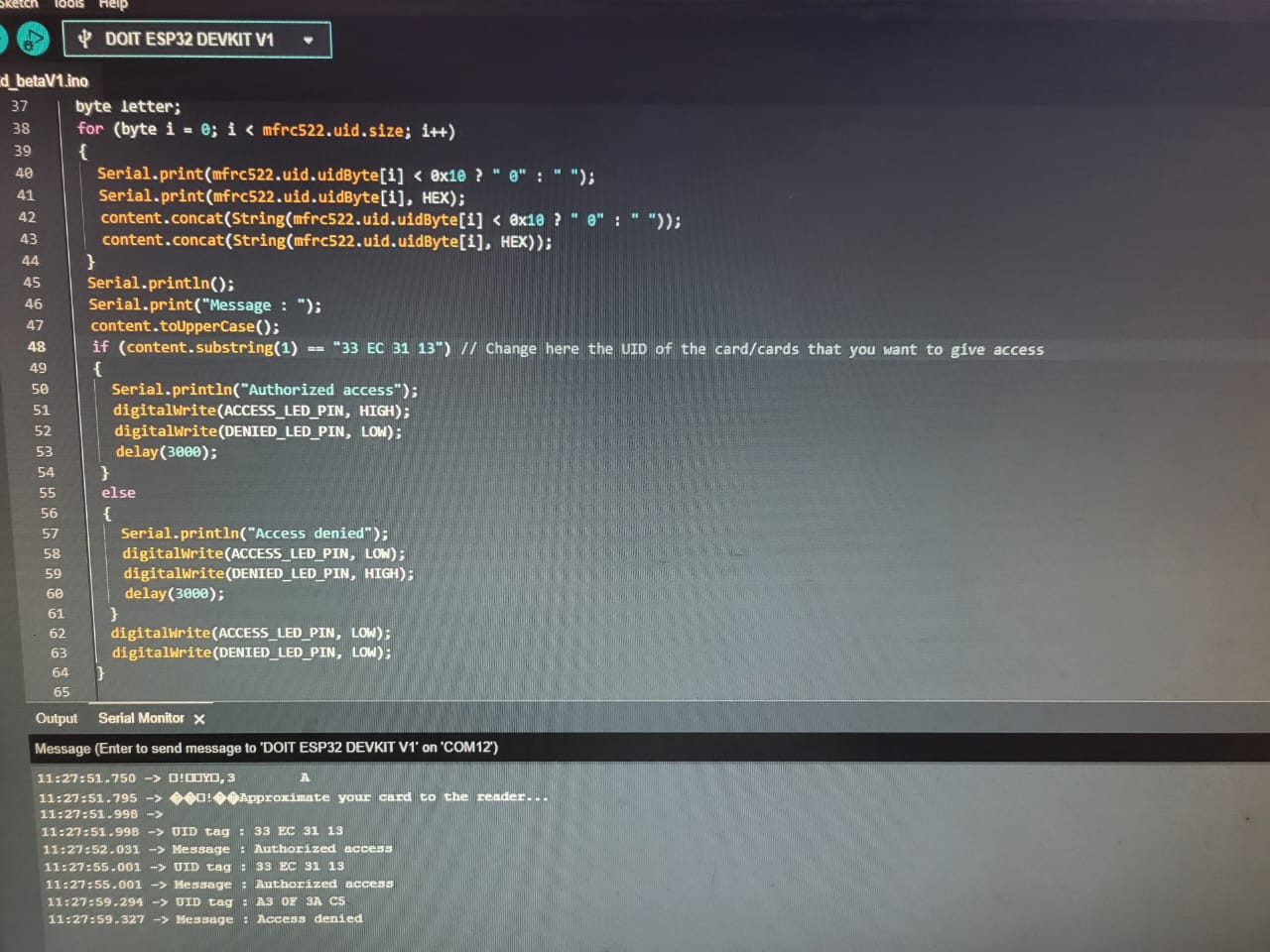
Task 2 - Interface ESP32 to read an RFID card with a reader display code in the serial monitor.
What is RFID
RFID cards are triggered by an electromagnetic pulse from a nearby reader device. The pulse induces flux, powers up the card, transfers data (UID), and the card responds to the reader. The circuit recognizes data from a specific card, allowing access only to that card.
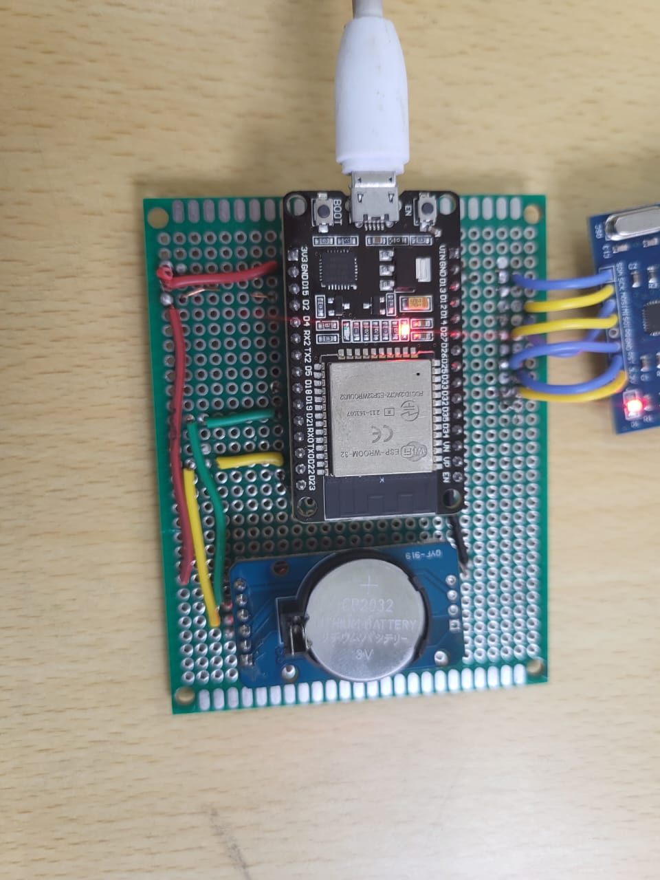
So How i did it
Assemble the circuit as shown in the provided diagram.

Write code to read the RFID card, identify the UID, and display "Access Denied" or "Access Approved" based on the UID assigned to the ESP32.
This is the code for the following
void loop() {
  Serial.println(\"Looking for RFID tag...\");
  // Look for new RFID cards
  if (mfrc522.PICC_IsNewCardPresent()) {
    Serial.println(\"RFID tag detected\");
    if (mfrc522.PICC_ReadCardSerial()) {
      Serial.print(\"UID tag :\");
      for (byte i = 0; i < mfrc522.uid.size; i++) {
        // Check if the byte value is less than 0x10 (16 in decimal)
        Serial.print(mfrc522.uid.uidByte[i] < 0x10 ? \" 0\" : \" \");
        // If true, print a leading zero to ensure each byte is printed with two characters
        // If false, print a space
        Serial.print(mfrc522.uid.uidByte[i], HEX);
        // Print the byte of the UID in hexadecimal format

      }
      Serial.println();

      // Check if
Watch the video here.
Task 3 - Interfacing RTC time module with ESP32
Interface a DS3231 RTC Module with ESP32 and display the time on the serial monitor.
An RTC (Real-Time Clock) module relies on a quartz crystal oscillator for a stable clock signal, which is divided to track time. It includes a backup battery for continuous operation when the main power is off. Control logic manages functions like time setting and alarms, while interrupts alert the system to specific events. Communication interfaces like I2C or SPI enable interaction with external devices for tasks such as setting time and configuring alarms, ensuring seamless integration into electronic systems.
How i did it
Connect the DS3231 RTC module to the ESP32.
Display the real-time clock information on the serial monitor. these are some of the code snippets
 DateTime now = rtc.now();// retrieves the current date and time from the RTC module and stores it in the

    Serial.print(now.year(), DEC);// Prints the year
    Serial.print('/');

    //similarly we can do for monthe inutes etc

    rtc.adjust(DateTime(F(__DATE__), F(__TIME__)));
    //this was used for adjusting time

Task 4 - Creating an attendance logger
I created an attendence logger using google sheets ad on extention for the website and using the ESp32 Since IFTT was not working.
How i Did it
First I made the connections as shown in the Video I defined GScriptId which holds the Deployment ID of the Google Apps Script. The Deployment ID uniquely identifies the Google Apps Script project.
The Google Apps Script is a cloud-based scripting language developed by Google that allows users to create automation and customize Google Apps. In this scenario, the Google Apps Script is used to receive HTTP POST requests from the ESP32 and write data to a Google Sheets spreadsheet.
The Deployment ID can be obtained by deploying the Google Apps Script as a web app. To do this, you need to follow these steps:
Open the Google Apps Script project. Click on "Deploy" > "New deployment". Choose "Web app" as the type of deployment. Click on "Deploy". Once deployed, you will get a Deployment ID, which you need to copy and paste into the GScriptId variable in the Arduino code. The Google Apps Script deployed as a web app should contain functions to handle HTTP POST requests and write data to Google Sheets. The Arduino code will send HTTP POST requests to the web app URL, triggering the execution of the corresponding functions in the Google Apps Script.
In summary, the GScriptId variable in the ESP32 code holds the Deployment ID of the Google Apps Script project, which allows the Arduino to communicate with the Google Apps Script deployed as a web app. So using the knowledge of the RFID tasks i use the same and modified code and did some changes in the esp32 pare of the code as shown below
Code
String values = \"\";
  for (byte i = 0; i < total_blocks; i++) {
    ReadDataFromBlock(blocks[i], readBlockData);
    if (i == 0) {
      data = String((char*)readBlockData);
      data.trim();
      student_id = data;
      values = \"\\\"\" + data + \" \";
    } else {
      data = String((char*)readBlockData);
      data.trim();
      values += data + \" \";
    }
  }
  values += gate_number + \"\\\"}\";
  payload = payload_base + values;

  // Publish data to Google Sheets
  Serial.println(\"Publishing data...\");
  Serial.println(payload);
  if (client->POST(url, host, payload)) {
    // If publish was successful, display success message on LCD screen
    Serial.println(\"[OK] Data published.\");

  } else {
    // If publish was not successful, display error message on serial monitor
    Serial.println(\"Error while connecting\");
  }
  // Add a delay before the next loop iteration
  delay(5000); // Delay is required before publishing again
So using the Gscript code is as such
// Get the current date and time
    var Curr_Date = Utilities.formatDate(new Date(), timezone, \"MM/dd/yyyy\");
    var Curr_Time = Utilities.formatDate(new Date(), timezone, \"hh:mm:ss a\");

    // Get the values from the data array sent from Arduino
    var value0 = dataArr [0];  //Student ID
    var value1 = dataArr [1];  //First Name
For time in and out
var data = sheet.getDataRange().getValues();
    var row_number = 0;
    var time_out = \"\";
    for(var i = 0; i < data.length ; i++){  // Search first occurrence of student id
      if(data[i][0] == value0){ //data[i][0] i.e. [0]=Column A, Student_id
        row_number = i+1;
        time_out = data[i][2] //time out [2]=Column C
        console.log(\"row number: \"+row_number); //print row number
        console.log(\"time out: \"+time_out); //print row number
        break; //go outside the loop
      }
    }
Task 5 - Communication using Zigbee protocol
Establish a communication between Arduino and ESP32 using zigbee protocols and transfer data from a sensor from one device to the other.
Problems Faced: As the zigbee module not connecting or being detected by the xbee app i couldnt do this task as such
Zigbee has its ability to form mesh networks. In a Zigbee mesh network, devices can act as routers to extend the range and reliability of the network. If a device is out of range of the coordinator (main controller), it can still communicate by routing messages through other devices in the network. This enables robust and scalable communication networks, especially in environments with obstacles or varying distances between devices.
Zigbee operates in the 2.4 GHz ISM (Industrial, Scientific, and Medical) band, which is license-free in most countries. Devices in a Zigbee network communicate using small data packets and can enter low-power sleep modes to conserve energy. This makes Zigbee suitable for battery-powered devices and applications requiring long battery life.
Task 6 - Controlling multiple peripherals using SPI Protocol
How I did it I made the connections as such shown in the video and hence from what i learnt from thr rfid task i changed the code a bit as when it reads a specific rfid reading it acts sends a message to the motor to change its direction or to enable in high or low state hence the motor moves when we give a 12V power supply and when a particular RFID is detected
Code
// Define the UID of the allowed RFID tag
byte allowedUID[] = {0xAB, 0xCD, 0xEF, 0x12}; //My UI n
void loop() {
  Serial.println(\"Looking for RFID tag...\");
  // Look for new RFID cards
  if (mfrc522.PICC_IsNewCardPresent()) {
    Serial.println(\"RFID tag detected\");
    if (mfrc522.PICC_ReadCardSerial()) {
      Serial.print(\"UID tag :\");
      for (byte i = 0; i < mfrc522.uid.size; i++) {
        // Check if the byte value is less than 0x10 (16 in decimal)
        Serial.print(mfrc522.uid.uidByte[i] < 0x10 ? \" 0\" : \" \");
        // If true, print a leading zero to ensure each byte is printed with two characters
        // If false, print a space
        Serial.print(mfrc522.uid.uidByte[i], HEX);
        // Print the byte of the UID in hexadecimal format

      }
      Serial.println();

      // Check if the detected UID matches the allowed UID
      if (compareUID(mfrc522.uid.uidByte, allowedUID)) {
        Serial.println(\"Access Approved\");
        moveMotor(); // Move the motor when the allowed RFID is detected
      } else {
        Serial.println(\"Access Denied\");
      }

      mfrc522.PICC_HaltA(); // Halt PICC
      mfrc522.PCD_StopCrypto1();  // Stop encryption on PCD4
    }
  }
  delay(500); // Add a small delay to reduce printing rate
}

// Function to compare two UID arrays
bool compareUID(byte uid1[], byte uid2[]) {
  for (byte i = 0; i < 4; i++) {
    if (uid1[i] != uid2[i]) {
      return false; // UIDs don't match
    }
  }
  return true; // UIDs match
}

void moveMotor() {
  digitalWrite(MOTOR_IN1_PIN, HIGH); // Set motor direction
  digitalWrite(MOTOR_ENA_PIN, HIGH); // Turn on motor
  delay(1000); // Motor movement duration
  digitalWrite(MOTOR_ENA_PIN, HIGH); // Turn off motor
}
Task 7 – Telegram Bot Motor Control
How i did it
Create a Telegram bot using the BotFather channel, obtaining a unique bot token. Implement code to link the ESP32 with the Telegram bot. Modify the provided code (originally for light control) to operate and reverse the motor in both directions.

Code:
#include \"AsyncTelegram.h\"
//for interfacing with the Telegram Bot API asynchronously.

//loop function

    if (myBot.getNewMessage(msg)) {
        // Process received messages
        if (msg.text.equalsIgnoreCase(\"On\")) {
            // Turn the motor ON in one direction
            digitalWrite(motor1Pin1, HIGH);
            digitalWrite(motor1Pin2, LOW);
            digitalWrite(enable1Pin, HIGH);
            myBot.sendMessage(msg, \"Motor is now ON in one direction\");
        } else if (msg.text.equalsIgnoreCase(\"Off\")) {
            // Turn the motor OFF
            digitalWrite(enable1Pin, LOW);
            myBot.sendMessage(msg, \"Motor is now OFF\");
        } else if (msg.text.equalsIgnoreCase(\"Reverse\")) {
            // Reverse the motor direction
            digitalWrite(motor1Pin1, LOW);
            digitalWrite(motor1Pin2, HIGH);
            digitalWrite(enable1Pin, HIGH);
            myBot.sendMessage(msg, \"Motor is now ON in the reverse direction\");
        } else {
            // Generate a welcome message with available commands
            String reply = \"Welcome to your Motor Control Bot!\
\";
            reply += \"You can use the following commands:\
\";
            reply += \"============================\
\
\";
            reply += \"1. On - Turn the motor ON\
\";
            reply += \"2. Off - Turn the motor OFF\
\";
            reply += \"3. Reverse - Reverse the motor direction\
\";
            myBot.sendMessage(msg, reply);
        }
    }

Turns the motor ON or OFF. Reverses the motor direction. Sends a welcome message with available commands if an unrecognized command is received.
Hence we can control by using the telegram bot
Task 8 - Alexa Light Control
In this home automation task i had to turn off and on the led bulb> I Tried many different ways Like rainmaker and other ways but it was not working as at last I stuck to using cadio software.
What is Cadio Software
It is a software that allows you to control the components via voice assistents(alexa and google) without using much of coding
How I did it
i first installed cadio firmware in the esp32 by flasing it using the official esp boot tiil in thw web and cadio firmwares using in the cadio websites then the esp32 emitts wifi which whill be detected by our phone as connect through it and then configure throuch pins by setting it up and then say which type of mode it is as a sensor or a bulb etc and using buttons or relays After the config put the common wifi between them and then go to the home app ad set up cadio and then we can use it in the google assistant in phone as the video below
Report is continued at
https://hub.uvcemarvel.in/article/e2407af0-ee7a-42a0-8716-b803998e3b0a
"