
COURSEWORK
Sinchana's D-P-001 course work. Lv 1
| Sinchana | AUTHOR | ACTIVE |
LEVEL 0 REPORT (Generic Tasks)
19 / 9 / 2025
TASK 1: 3D Printing
What is 3D Printing
3D printing is the process of creating three-dimensional objects layer by layer from a digital model.
The Process
- Create or download a 3D model (STL file).
- Slice the model using software like Ultimaker Cura or Creality Slicer to generate G-code.
- Set printer parameters and send the G-code to the 3D printer.
- The printer deposits material layer by layer to build the object.
What I Learned
- Bed Temperature: For PLA, typically 50–60°C to help the first layer stick and prevent warping.
- Nozzle Temperature: For PLA, typically 190–220°C to melt the filament properly.
- Infill Density: Determines the internal strength of the print.
- Low infill → lighter prints
- High infill → stronger prints
Task 2 – API
What is an API?
API stands for Application Programming Interface. It is a set of rules and protocols that allows different software applications to communicate with each other. APIs enable developers to access specific features or data of another application, service, or platform without needing to understand its internal workings.
In simple terms, an API acts as a bridge between two systems, enabling one application to send requests and receive responses (usually in formats like JSON or XML).
Example: Quiz Mania Web App
As part of this task, I developed a Quiz Web Application called Quiz Mania, which demonstrates how an API can be integrated into a real-world project.
- The app fetches quiz questions from the Open Trivia API.
- Users can select and attempt various quiz questions directly within the app.
- The app dynamically retrieves data from the API and displays it in a user-friendly format.
- This project highlights how APIs simplify the process of incorporating real-time, external data into a web application.
https://sinchanar16.github.io/quiz-mania/
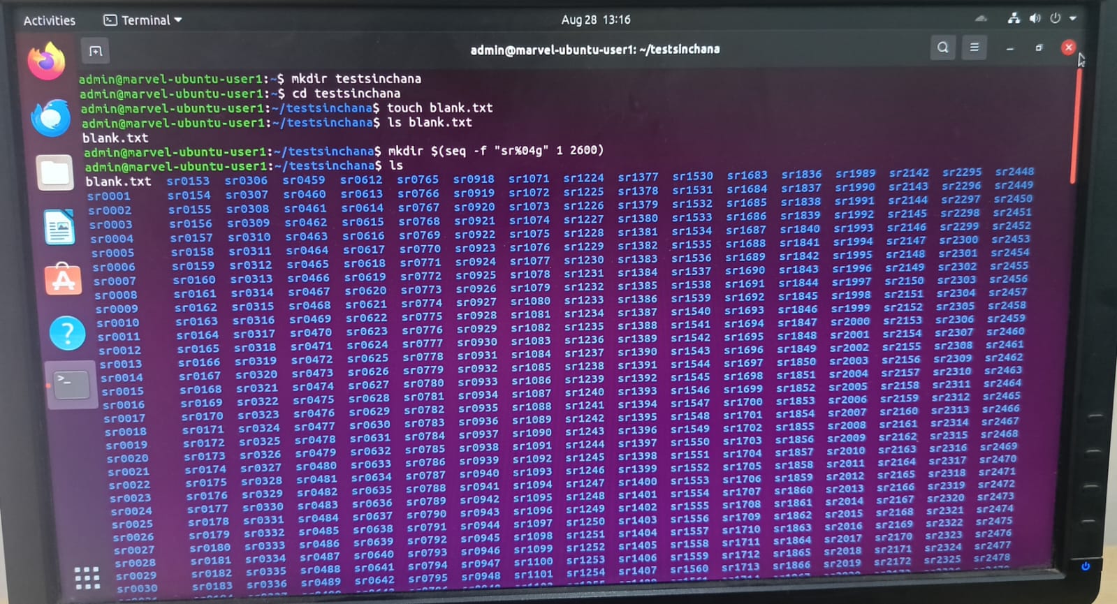
TASK 4: Get familiar with the command line on Ubuntu
I proceeded on to complete the given task where I created a test folder and opened it in which I created 2600 folders and two text files. Further, I concatenated the 2 text files and showed the result on the terminal. Through this task, I learnt a few basic command lines in Ubuntu.
- Created a folder using mkdir testsinchana.
- Opened it with cd testsinchana.
- Created blank.txt using touch blank.txt.
- Created 2600 folders (sr0001 to sr2600) using mkdir $(seq -f "sr%04g" 1 2600).
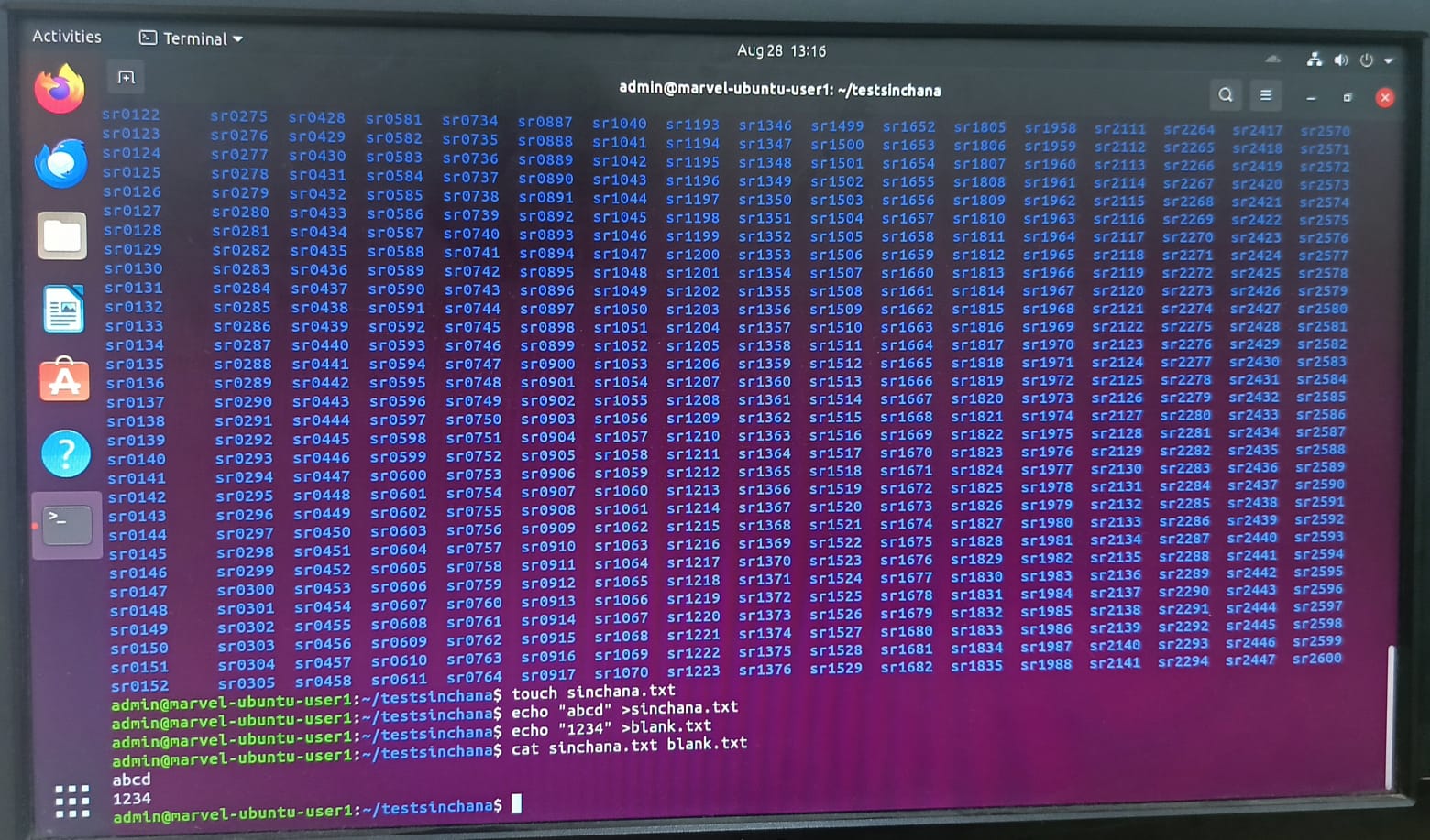
- Created sinchana.txt using touch sinchana.txt.
- Added “abcd” to sinchana.txt using echo "abcd" > sinchana.txt.
- Added “1234” to blank.txt using echo "1234" > blank.txt.
- Concatenated both files using cat sinchana.txt blank.txt and displayed the output.
TASK 7: Portfolio Webpage
Using HTML,CSS and JavaScript,I created my own portfolio webpage that displays information about me.


Link to my code: https://github.com/Sinchanar16/portfolio-webpage
TASK 8: Writing Resource Article Using Markdown
I wrote an article on Cloud Computing that explains its basic concepts, advantages, and real-world applications. The article covers how cloud computing works, different service models, and its impact on businesses and technology.
Link to the article: https://github.com/Sinchanar16/cloud-computing-article/blob/main/cloud_computing.md
Task 9: Tinkercad
Tinkercad is an online 3D design and modeling tool used for creating 3D objects and circuits. It allows us to test our projects virtually before implementing them in hardware. From this task, I learned how to create and simulate circuits using Tinkercad. I simulated a circuit in that measures distance using ultrasonic sensor and displayed on LCD.
Working Principle:
- The transmitter sends out ultrasonic sound waves.
- These waves travel in air, hit the object ,and bounce back.
- The receiver detects the reflected waves and measures how long it took for the waves to return. With this we can calculate the distance between the sensor and the object.

Tinkercad Simulation: Click here to view
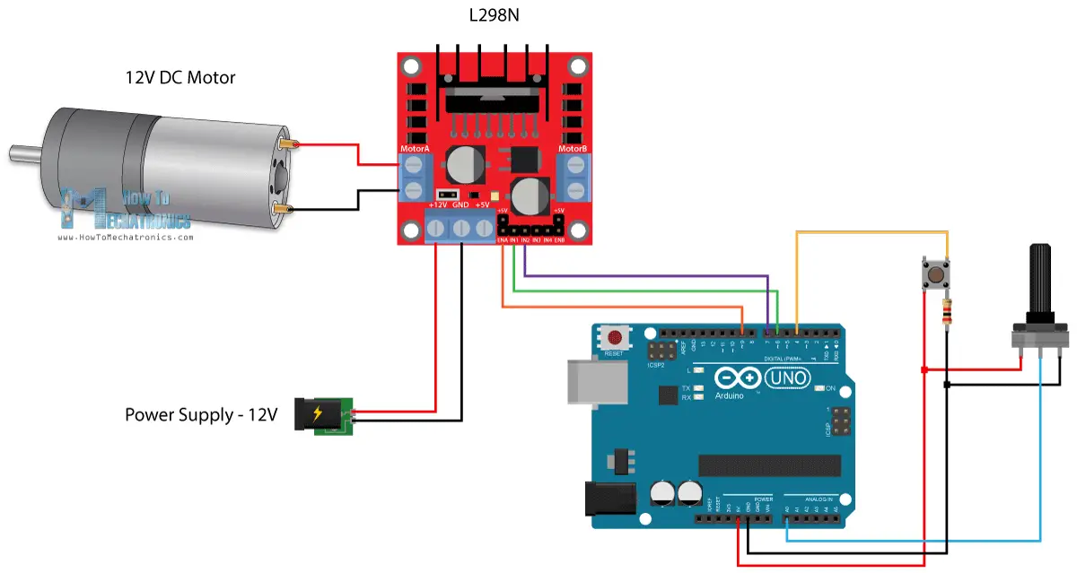
TASK 10: Speed Control of DC Motor
In this task, I learned how to control a DC motor using an Arduino and an L298N motor driver. This project helped me understand how to control a 5V DC motor and regulate its speed using PWM (Pulse Width Modulation).
Working Procedure
- The Arduino controls the speed and direction of a DC motor using the L298N motor driver.
- The Arduino sends digital signals to the L298N to control the motor's direction through the IN1 and IN2 pins.
- The motor's speed is controlled by sending a Pulse Width Modulation (PWM) signal to the ENA pin of the L298N.
- The L298N uses an H-Bridge circuit to change the direction of the current flow, which in turn adjusts the motor's rotation direction (clockwise or counterclockwise).
- The speed of the motor is regulated by varying the duty cycle of the PWM signal, where 0% duty stops the motor, and 100% duty runs the motor at full speed.
- The motor is powered through the OUT1 and OUT2 pins of the L298N, with a 5V power supply.
speed control of dc motor: Watch here
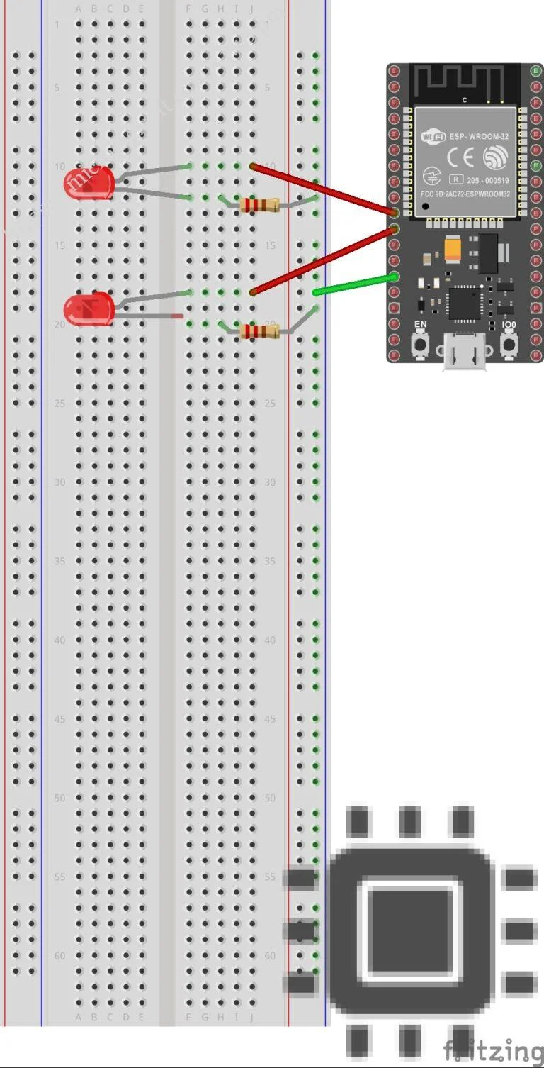
TASK 11: LED Toggle Using ESP32
In this task, I worked with the ESP32 and learned how to control an LED over a web interface.
Steps followed:
- Familiarized myself with the ESP32 board.
- Made the necessary connections for the LED.
- Firstly, I selected the correct board type(ESP32) in the Arduino IDE.
- Uploaded the code using Arduino IDE to make the ESP32 act as web server and entered my network credentials, this will allow the ESP32 to connect to my WI-FI network and listen for requests from a web page.
- Obtained the IP address of the web server, which was shown on the Serial Monitor.
- Used the ON/OFF buttons on the web page to control the LED and verify its working.
led toggle: Watch here
TASK 12: SOLDERING PREREQUISITES
First I learnt about the soldering tools.
I learnt about soldering iron, solder, flux etc.
I mounted the components that is LED and the resistor to the circuit board and then soldered it.
Below is the picture of the performed task:

Task 13 – 555 Astable Multivibrator
Objective
Set up a 555 timer in astable mode and observe its output waveform.
A 555 astable multivibrator is an electronic circuit that generates a continuous square wave signal without any external triggering. It alternates between high and low states automatically, producing a pulse waveform. The duty cycle determines the proportion of time the signal stays high in one cycle.
Procedure
-
Assembled the 555 timer on a breadboard in astable mode.
-
Powered the circuit and connected the DSO to the output pin.
-
Observed the square wave output on the DSO.
-
A continuous square wave was obtained at the output.
-
The waveform showed the high and low periods of the signal.

Task 14 – Karnaugh Maps and Logic Circuit
In this task,I had to design a burglar alarm. here i have denoted the door:lock= 0, open= 1; key:pressed= 1 and not pressed = 0. The alarm is activated only when the door is open witout key being pressed (when a thief breaks into a home). So the truth table is as follows:

To derive the logic circuit to the above truth table,i have used k-map:

From the k-map we get A=DK'from which we get the logic circuit as above. The burglar alarm is denoted by 'A', where 1 means the alarm is activated and 0 means the alarm is off. I simulated the above logic circuit in tinkercad:

simulation:
Task 15 – Active Participation
Completed the Basics of Electronics and Programming course on Infosys Springboard.

TASK 16 – Datasheets Report Writing:
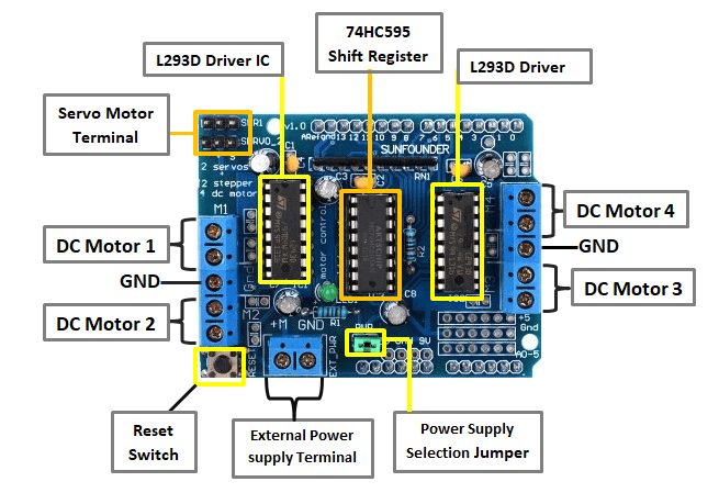
Report on L293D Motor Driver
Introduction To L293D
The main function of the L293D motor driver IC is to control the direction and speed of DC and stepper motors by allowing current flow in both directions and amplifying control signals from a microcontroller. It provides a safe interface between low-power control circuits and high-power motor loads. The IC includes protection features such as flyback diodes to prevent damage from voltage spikes, and it supports speed control using PWM signals. It is widely used in robotics, automation, and educational projects due to its ease of use, reliability, and compact design.
IC Details
- Name: L293D
- Type: Quadruple high-current half-H driver IC
- Function: Controls two DC motors or one stepper motor independently
- Technology: Uses bipolar junction transistors (BJTs) for switching high current loads
- Operating Voltage: 4.5V – 36V for motor supply, typically 5V for logic control
- Output Current: 600 mA continuous per channel, 1.2 A peak
- Features:
- Built-in flyback diodes for protection
- Thermal shutdown to prevent overheating
- Supports PWM-based speed control
- Allows bidirectional control using an internal H-bridge

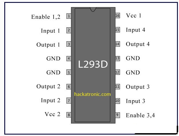
Pin Configuration
The L293D has 16 pins, each serving a specific function:
- Pin 1 (EN1): Enable pin for Motor 1 – used for speed control with PWM.
- Pin 2 (IN1): Input pin to control Motor 1 direction.
- Pin 3 (OUT1): Output connected to one terminal of Motor 1.
- Pin 4 (GND): Ground connection.
- Pin 5 (GND): Ground connection.
- Pin 6 (OUT2): Output connected to the other terminal of Motor 1.
- Pin 7 (IN2): Input pin to control Motor 1 direction.
- Pin 8 (VCC2): Motor supply voltage (4.5V to 36V).
- Pin 9 (EN2): Enable pin for Motor 2 – used for speed control with PWM.
- Pin 10 (IN3): Input pin to control Motor 2 direction.
- Pin 11 (OUT3): Output connected to one terminal of Motor 2.
- Pin 12 (GND): Ground connection.
- Pin 13 (GND): Ground connection.
- Pin 14 (OUT4): Output connected to the other terminal of Motor 2.
- Pin 15 (IN4): Input pin to control Motor 2 direction.
- Pin 16 (VCC1): Logic supply voltage (typically 5V).
Internal Structure
The internal structure of the L293D consists of:
- Four power transistors (BJTs): Arranged in an H-bridge to control current flow through the motors.
- Logic circuitry: Decodes input signals and manages transistor switching.
- Enable circuitry: Controls motor operation and accepts PWM signals for speed adjustments.
- Protection diodes: Prevent damage from voltage spikes caused by inductive loads.
This structure ensures efficient operation, protection against reverse currents, and safe motor control.
PWM (Pulse Width Modulation)
Pulse Width Modulation (PWM) is used in the L293D to regulate motor speed by controlling how long the motor receives voltage.
- The enable pins (EN1 and EN2) receive PWM signals from the controller.
- A higher duty cycle means more power is supplied, increasing motor speed.
- A lower duty cycle means less power, slowing the motor.
- PWM frequencies around 1 kHz or higher are commonly used to reduce noise and ensure smooth operation.
- It allows fine control over motor speed without excessive power loss or heat buildup.
H-Bridge
The H-bridge inside the L293D allows current to flow in both directions through the motor.
- It consists of four transistors arranged in a bridge formation.
- Forward motion is achieved by closing one diagonal pair of transistors.
- Reversing the motor’s rotation is done by closing the opposite pair.
- Opening all switches allows the motor to coast freely.
- The configuration ensures safe and efficient motor control without external circuitry.

Working of L293D
- Power Supply: Motors are connected to output pins, with power supplied through VCC2, and logic control through VCC1.
- Direction Control: Logic signals applied to input pins (IN1–IN4) determine which transistors switch on, controlling the motor’s direction.
- Speed Control: PWM signals applied to enable pins (EN1, EN2) regulate the motor’s speed.
- Protection: Internal diodes protect the IC from voltage spikes, and logic prevents conflicting states.
- Operation: By coordinating inputs and PWM signals, the IC enables the motor to move forward, reverse, stop, or brake safely and efficiently.

Task 17: Introduction to Virtual Reality (VR)
Virtual Reality (VR): Through this task,I learned about Virtual Reality(VR) and Augumented Reality (AR) and understood the difference between VR and AR. I made a report on the differences between VR and AR, mentioned about the technology being developed by Indian companies in this space.
Link to my report:https://github.com/Sinchanar16/vr-vs-ar/blob/main/vr.md