
COURSEWORK
Ayush's AIR-001 course work. Lv 1
| Ayush Bhatt | AUTHOR | ACTIVE |
LEVEL 0 REPORT
24 / 9 / 2025
Project Task Report
GT-01: 3D Printing
Aim To understand the working of a 3D printer from online sources, and to learn about bed temperature and other printer settings.
Outcomes & Learning
- PLA (Polylactic Acid)
- One of the most widely used plastics in additive manufacturing.
- Considered more sustainable since it is sourced from natural and renewable resources, unlike petroleum-based plastics.
- Bed Temperature
- PLA/PLA+ can be printed on an unheated bed.
- For best results: 50°C – 60°C.
- Cooling
- PLA prints best when rapidly cooled with the aid of the extruder’s fan.
- Ensures clean, crisp layers with neat details.
- For maximum surface resolution: Set fan speed to 100%.
- Printing Speed
- For better results: keep speed ≤ 55 mm/s.
- Helps achieve great surface resolution.
- Post-Printing Procedures
a. Joining 3D Printed Parts
- Use cyanoacrylate glue (superglue) or two-stage epoxies for PLA parts.
b. Painting
- Almost all 3D printed parts can be painted (except Nylon and PETG).
c. Sanding
- Use progressively finer sandpaper for smooth surface finishes.
- Sand slowly to avoid breaking parts or melting due to friction.
Note
Due to time constraints in the lab, I was unable to print a model. In the future, I will definitely print a model to apply these learnings.
GT-02: API
AIM : Learn what an API is and how it works. Using any API, build a user interface to make calls and display information.
LEARNINGS :
An API (Application Programming Interface) acts as an interface between different applications and allows them to share data and information.
I created a weather webpage using the OpenWeather API.
.png)
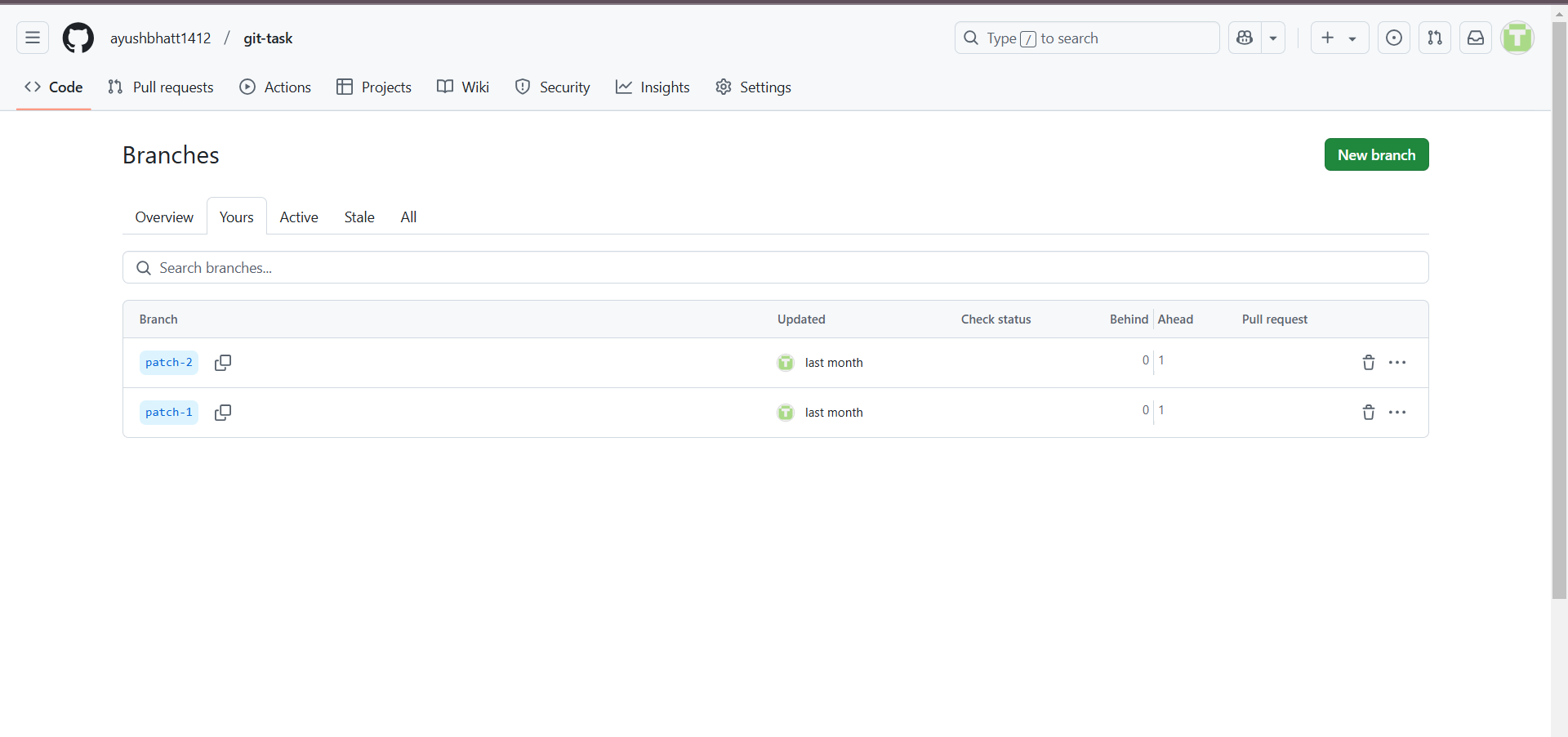
GT-03: GitHub
AIM : Familiarize with GitHub workflows such as Actions, Issues, and Pull Requests.
LEARNINGS :
GitHub is a collaborative platform for version control and project hosting. It is a very great place to work and collaborate on a project oer any work.
Here I have forked a repository and after correcting the code I have send pull request to the main branch in repository.
GT-04: Ubuntu Command Line
AIM : Get familiar with Ubuntu CLI and perform basic subtasks.
LEARNINGS : Practiced essential Linux commands.
| Command | Purpose |
|---|---|
mkdir test | Create a folder named test |
cd test | Enter folder |
touch blank.txt | Create empty file |
ls | List files |
mkdir M{0001..2600} | Create 2600 folders |
cat file1.txt file2.txt | Concatenate files |
.png)
.png)
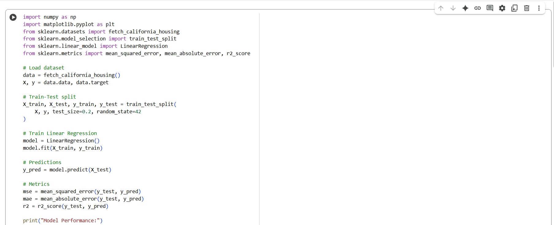
GT-05: Linear Regression from Scratch
AIM : Implement Linear Regression from scratch using the California Housing dataset.
LEARNINGS :
- Basics of machine learning.
- Built a model to predict property prices.
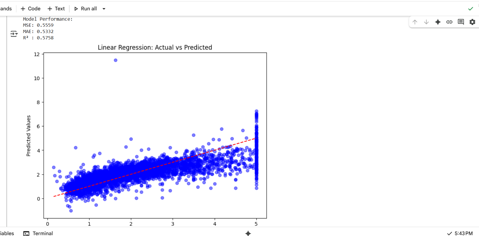
Model Performance:
- MSE:
0.5559 - MAE:
0.5332 - R² :
0.5758
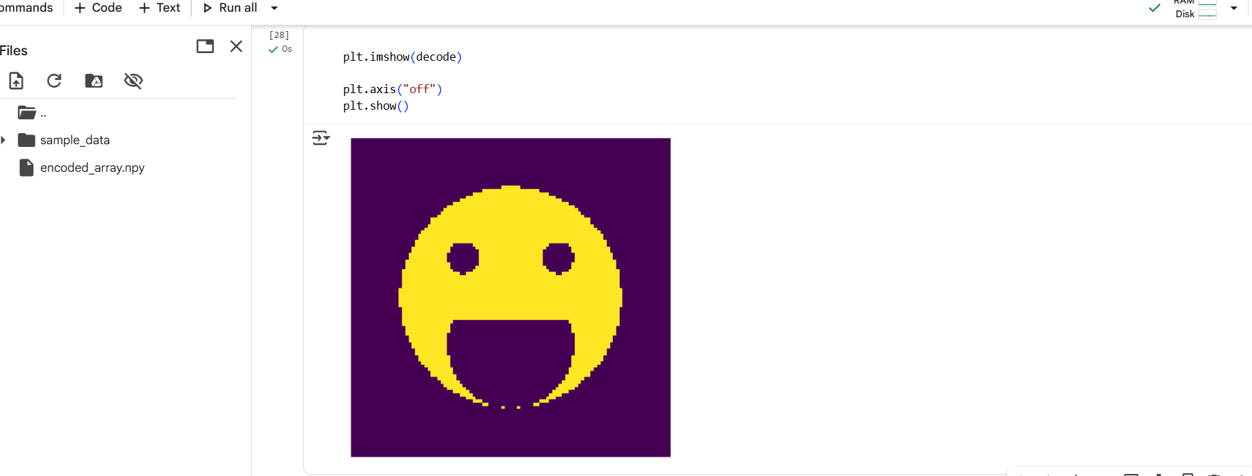
GT-06: Matrix Puzzle (NumPy & Matplotlib)
AIM : Decode a scrambled matrix and reveal the image using NumPy & Matplotlib.
LEARNINGS : Learned basics of NumPy (reshape, slice, transpose) and Matplotlib visualization.
GT-07: Portfolio Webpage
AIM : Create a website to showcase portfolio, including personal info, interests, and projects.
LEARNINGS : Learned basics of HTML and CSS while developing the site.
.png)
GT-08: Technical Article (Markdown)
AIM : Write a resource article on UAV applications using Markdown.
LEARNINGS :
I wrote about UAVs in Precision Agriculture, exploring how drones improve farming efficiency.
GT-09: Tinkercad Radar System
AIM : Create a Tinkercad account & build a simple radar circuit using an ultrasonic sensor.
LEARNINGS :
- Learned Tinkercad simulation basics.
- Built a radar system using ultrasonic sensor + servo motor.
.png?raw=true)
GT-10: DC Motor Speed Control
AIM : Control DC motor speed using Arduino UNO + L298N motor driver.
LEARNINGS : Controlled a 5V DC motor using potentiometer and motor driver.
L268N motor driver The L298N motor driver is a widely used module for controlling the speed and direction of DC motors and stepper motors. Based on the dual H-Bridge concept, it allows independent control of two motors simultaneously. It supports an operating voltage range of 5V to 35V and can supply up to 2A current per channel, making it suitable for medium-power applications. Using PWM (Pulse Width Modulation) signals from a microcontroller like Arduino or ESP32, the motor’s speed and direction can be precisely controlled. Due to its efficiency, affordability, and ease of use, it is commonly used in robotics, automation, and DIY projects.
H Bridge An H-Bridge is an electronic circuit used to control the direction of a DC motor by allowing current to flow in either direction through it. The circuit gets its name because its typical layout looks like the letter H. It consists of four switches (transistors or MOSFETs) arranged in an H-like configuration. By turning ON two switches at a time (one from the left side and one from the right side), current flows through the motor in a chosen direction. Reversing the switch pair reverses the motor’s direction.When combined with PWM signals, it also enables speed control.The L298N motor driver is a practical example of an H-Bridge circuit.
Diagram Of H Bridge
    +Vcc
     |
 [S1]   [S2]
   |     |
   |     |
   +--M--+
   |     |
   |     |
 [S3]   [S4]
     |
    GND
S1, S2, S3, S4 are switches/transistors. Close S1 & S4 → Forward rotation. Close S2 & S3 → Reverse rotation. Never close S1 & S2 or S3 & S4 together (it causes a short circuit)
.png?raw=true)
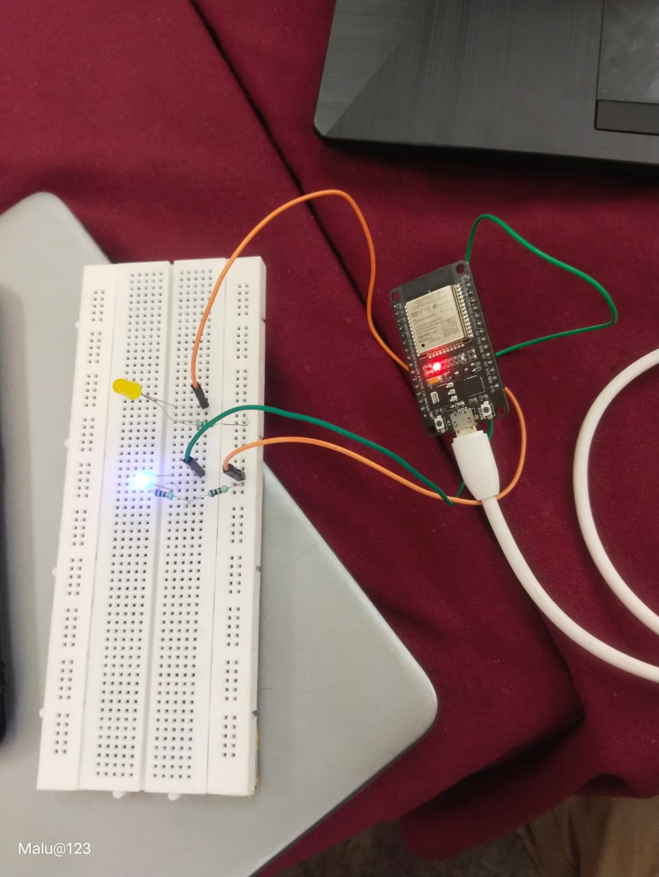
GT-11: ESP32 LED Toggle
AIM : Create a standalone ESP32 web server to toggle LED via GPIO.
LEARNINGS : Built and tested ESP32 web server for LED control.
The ESP32 is a highly versatile and powerful microcontroller developed by Espressif Systems, widely used in IoT, robotics, and automation projects. It comes with a dual-core 32-bit processor, clock speed up to 240 MHz, and integrated Wi-Fi and Bluetooth (Classic + BLE), making it ideal for wireless applications. The ESP32 includes a variety of peripherals such as GPIOs, ADC, DAC, PWM, UART, SPI, and I2C, along with ample flash memory and SRAM for complex tasks. Known for its low power consumption, it supports deep-sleep modes, making it suitable for battery-powered devices. Its affordability and flexibility make it a favorite among developers and hobbyists.
| Pic 1 | Pic 2 | Web Interface |
|---|---|---|
 | 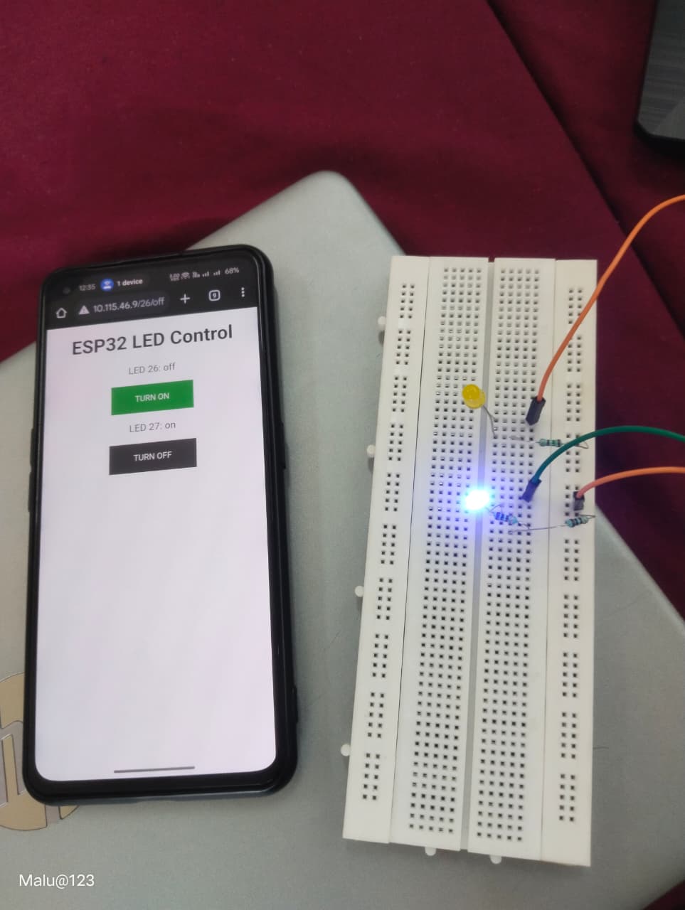 |  |
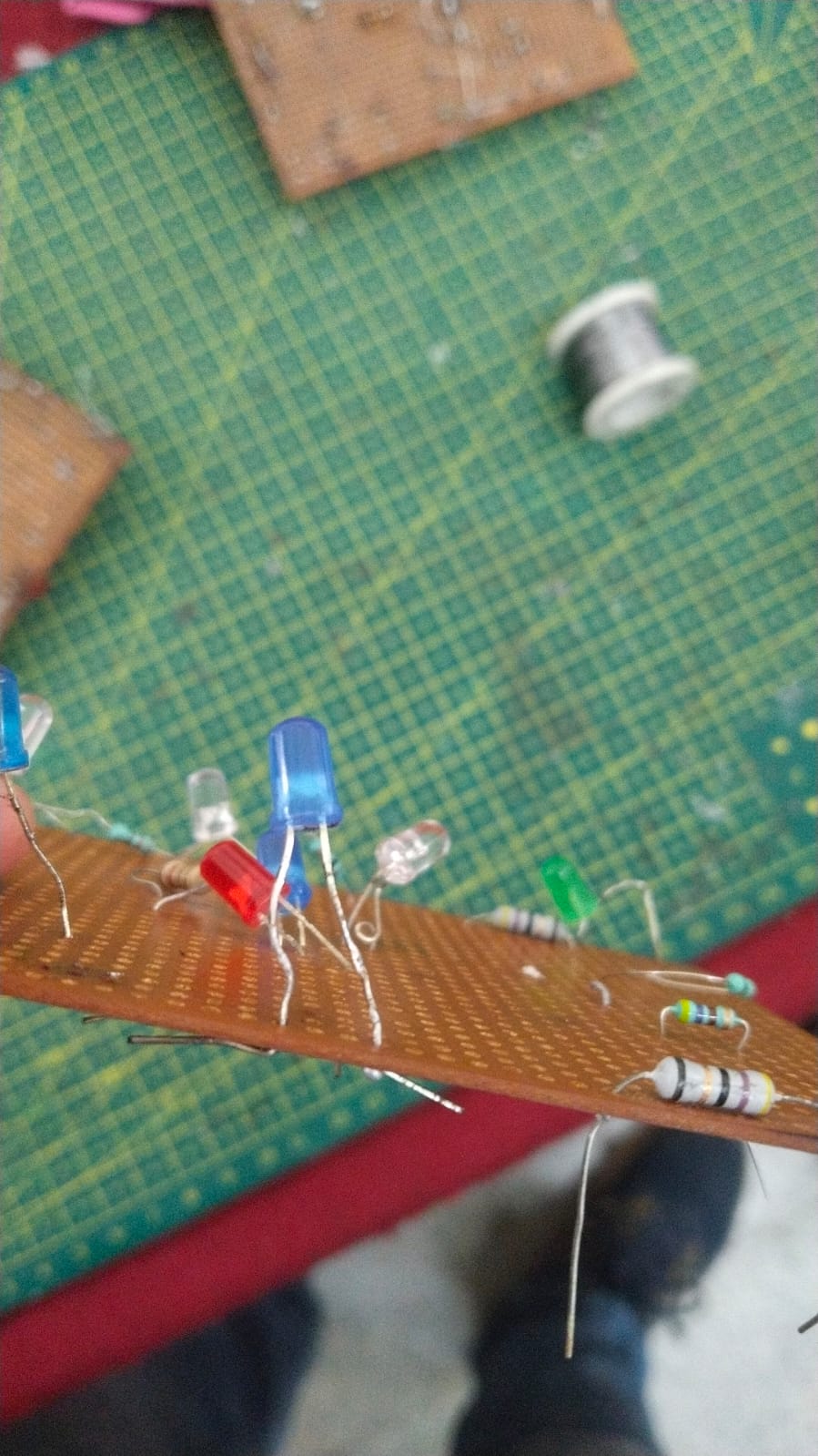
GT-12: Soldering Practice
AIM : Learn soldering equipment and perform basic LED circuit soldering.
LEARNINGS : Successfully soldered an LED circuit on a perf board.
GT-13: 555 Astable Multivibrator (60% Duty Cycle)
Aim To design and assemble a 555 Astable Multivibrator with a duty cycle of 60%, and to observe the output waveform using a Digital Storage Oscilloscope (DSO).
Components Required
- 555 Timer IC (NE555)
- Resistors: R1 = 6.8 kΩ, R2 = 10 kΩ
- Capacitor: C = 0.01 µF
- Breadboard
- Connecting wires
- Power supply (5V–9V DC)
- Digital Storage Oscilloscope (DSO)
Theory
The 555 timer is a versatile IC that can be used as a timer, pulse generator, or oscillator.
In astable mode, it works as an oscillator and generates a continuous square wave without any external trigger.
The timing depends on the values of two resistors (R1, R2) and a capacitor (C).
Formulas:
- Time High (TH) = 0.693 × (R1 + R2) × C
- Time Low (TL) = 0.693 × R2 × C
- Total Period (T) = TH + TL
- Frequency (f) = 1 / T
- Duty Cycle (D) = (TH / T) × 100
For duty cycle = 60%:
[
\frac{R1 + R2}{R1 + 2R2} = 0.6
]
Design
- Select C = 0.01 µF (10nF).
- Assume R1 = 6.8 kΩ.
- From the duty cycle equation, calculate R2.
[ \frac{R1 + R2}{R1 + 2R2} = 0.6 ]
Solving gives R2 ≈ 10 kΩ.
Final values:
- R1 = 6.8 kΩ
- R2 = 10 kΩ
- C = 0.01 µF
Circuit Diagram
Connections of 555 timer in astable mode:
- Pin 1 → GND
- Pin 8 → Vcc
- Pin 4 → Vcc (to disable reset)
- Pin 5 → Capacitor (0.01 µF) to GND
- R1 → Between Pin 7 and Vcc
- R2 → Between Pin 7 and Pins 2 & 6
- Capacitor C → Between Pins 2 & 6 and GND
- Pin 3 → Output
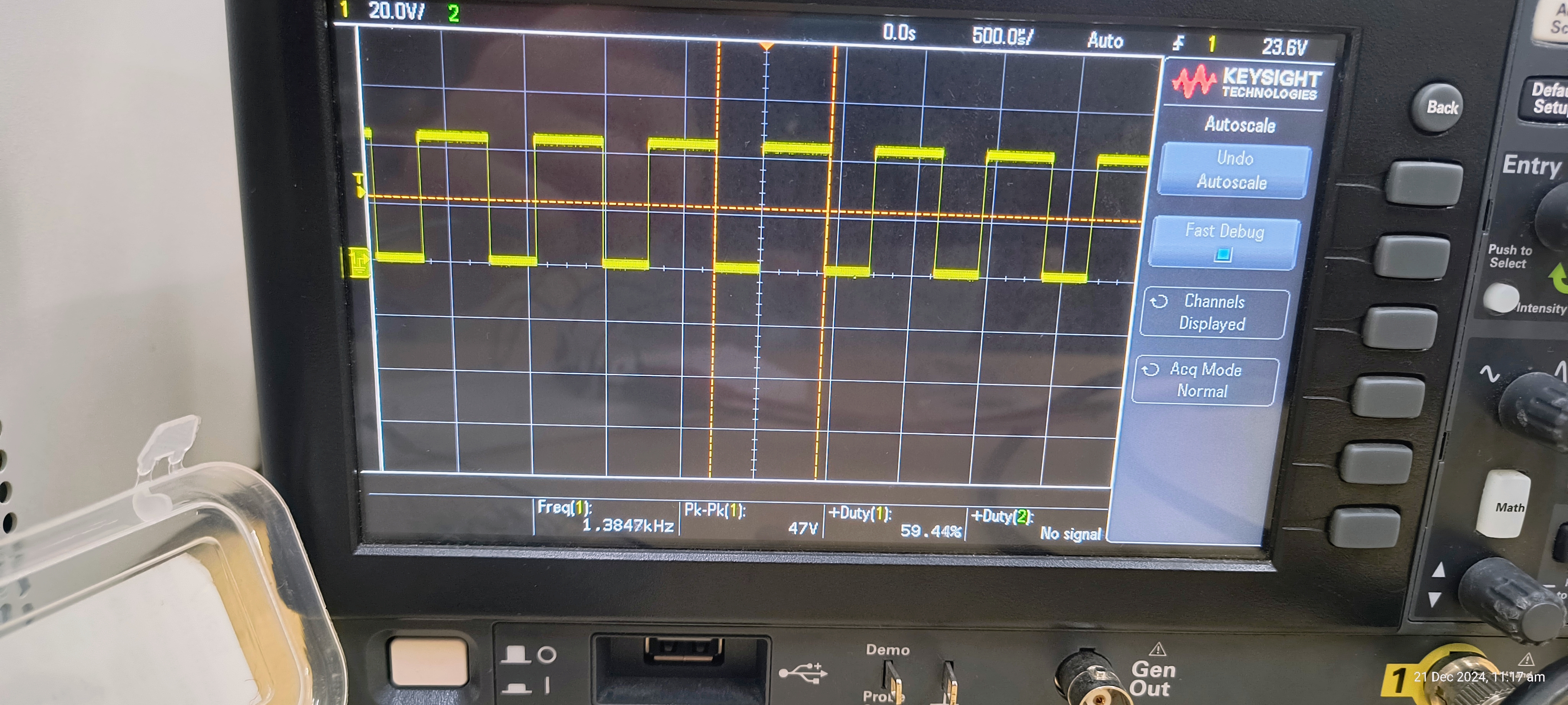
Observation
- The output waveform was observed on the DSO.
- It was a square wave.
- The duty cycle was around 60%, matching the design.
- Frequency matched the calculated range.
Conclusion
A 555 Astable Multivibrator with 60% duty cycle was successfully designed and assembled on a breadboard.
The output square waveform was observed on the DSO, and it matched the calculated results.
GT-14: Active Participation
I participated in Marvel Ideathon and DSA workshop conducted by E cell
GT-15: Introduction to VR
AIM : Study Virtual Reality, its difference from AR, and emerging trends.
LEARNINGS :
- Reality is categorized into VR, AR, and MR.
- Report highlights tech stack + Indian companies in VR.