3 / 4 / 2025
TASK 1: ASSEMBLY AND SIMULATION
Gripper design, assembly and simulation
Gripper: A gripper is a mechanical device used to grasp, hold, or manipulate objects in various automation, robotics, and industrial applications. Grippers are commonly used in systems where precise handling of parts is needed, such as in assembly lines or robotic arms. Gripper had a wide range of applications, they are used in Manufacturing and Assembly, Packaging, Material Handling, Pick-and-Place Operations, Quality Control, Medical Devices. Designing and assembling the gripper in Fusion 360 was a great learning experience. Since I had some previous experience with 2D and 3D modeling in Level 1, the design of individual parts like the base, arms, linkages, and mounts was relatively easy. But the real challenge came during the assembly process. Aligning the components correctly and ensuring smooth movement took some effort. Once the parts were assembled, I moved on to the simulation phase. I tested the gripper’s movement to ensure everything was functioning as expected. I used different joint types like rigid, revolute, and slider joints in Fusion 360 to define how the parts should move. There were definitely some challenges along the way, especially in figuring out how to make everything move smoothly without interference, but solving those problems helped me learn a lot about managing assemblies.
Design Process:
- Sketching
- Modeling
- Material Selection
- Testing
Assembly Process: -
- Using Joints
- Aligning Components
- Applying Motion Study
- Testing the Assembly
- Final Adjustments.


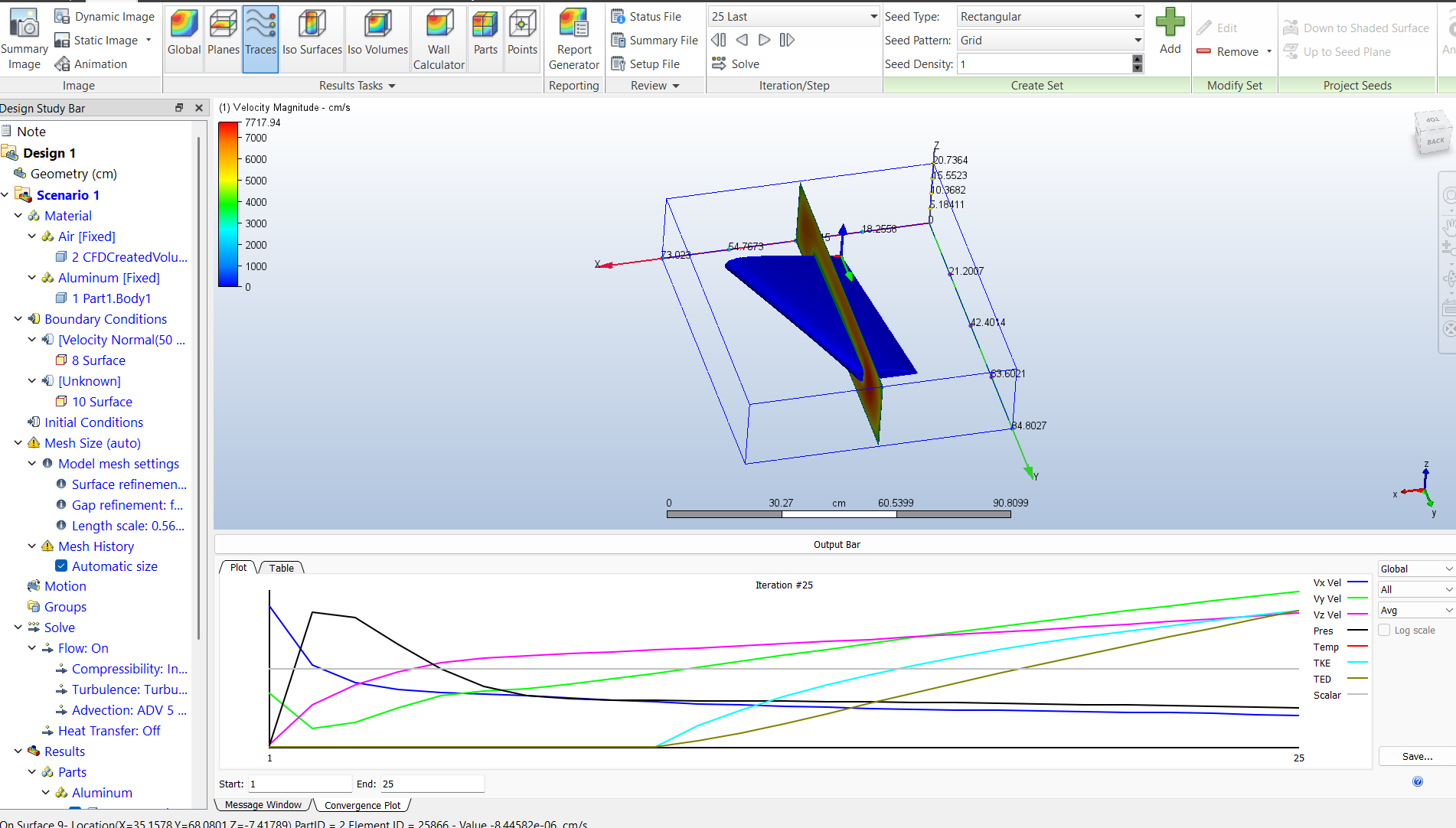
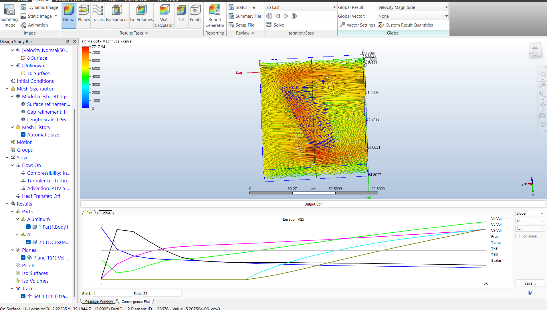
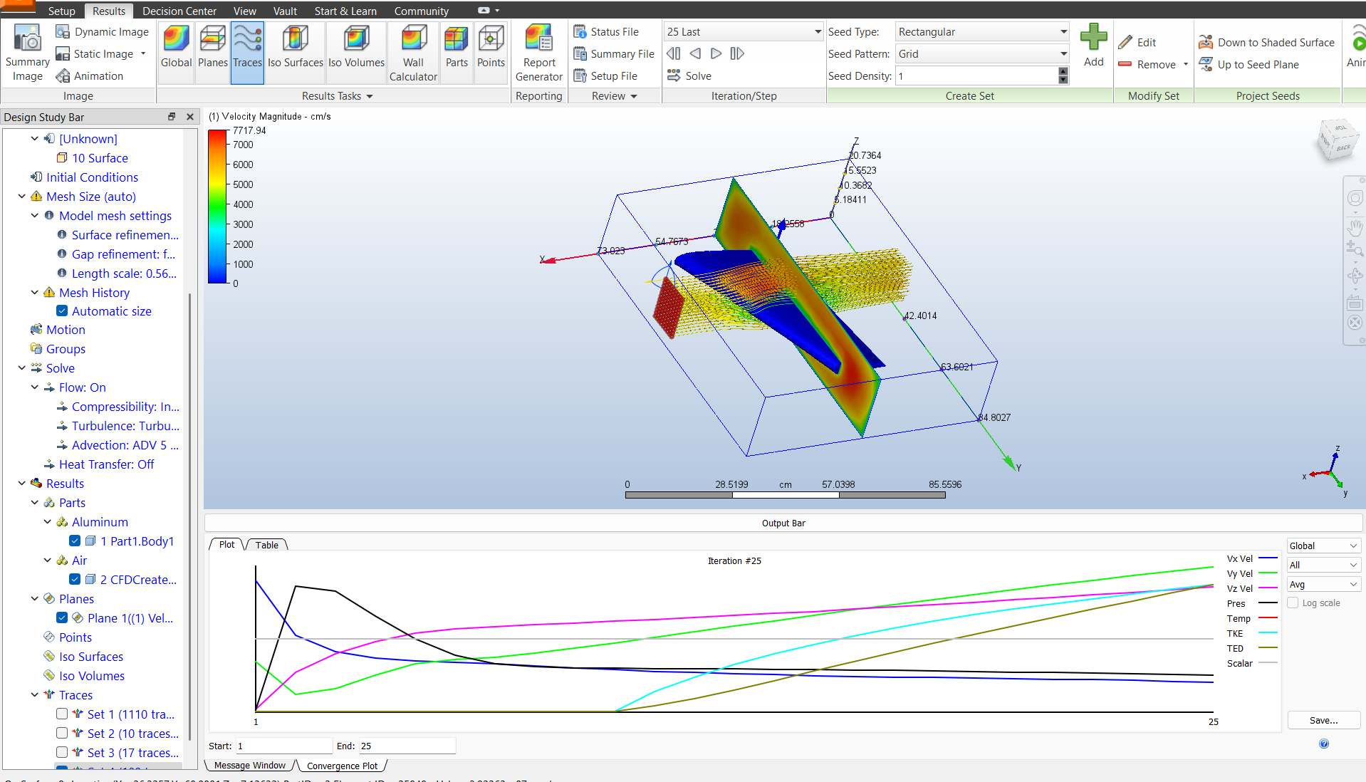
TASK 2: Computational Fluid Dynamics
TASK 3: Generative Design
Generative Design is an advanced design process that uses artificial intelligence (AI) and machine learning algorithms to generate a variety of design solutions based on predefined parameters. Rather than manually designing a part, generative design allows the software to explore a wide range of possible shapes and configurations, all while meeting specific design constraints (such as strength, material, weight, and manufacturing constraints).
- In essence, you provide the software with goals, such as desired weight, strength, or material constraints, and the software generates a number of potential designs that meet those requirements. The result is typically a highly optimized structure that might not be something a designer would have thought of in traditional methods. The key uses of generative design include:
- Optimization
- Innovation
- Material Efficiency
- Complex Geometry
- Faster Prototyping
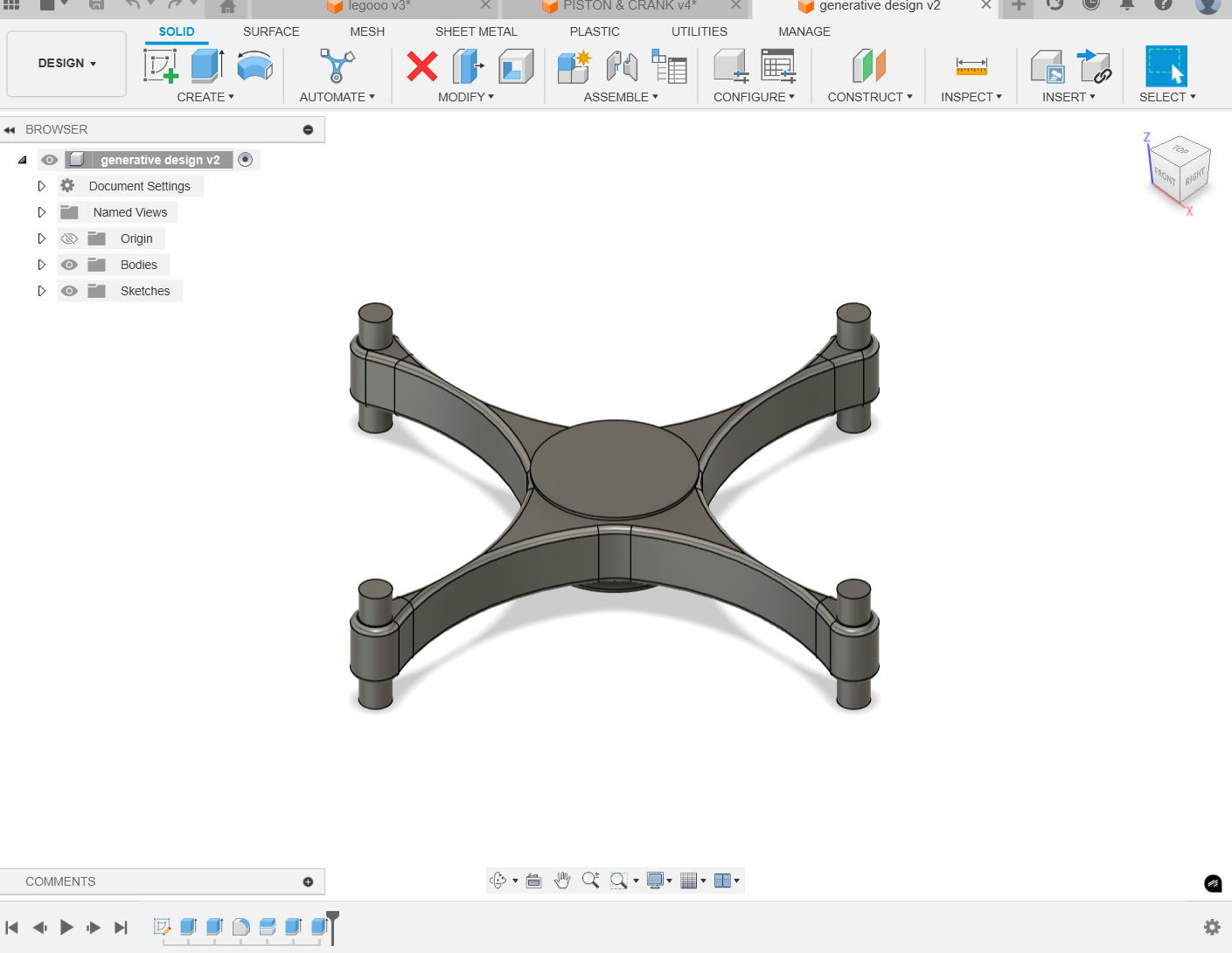
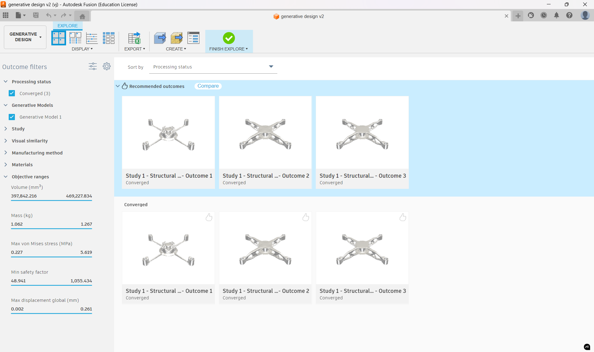
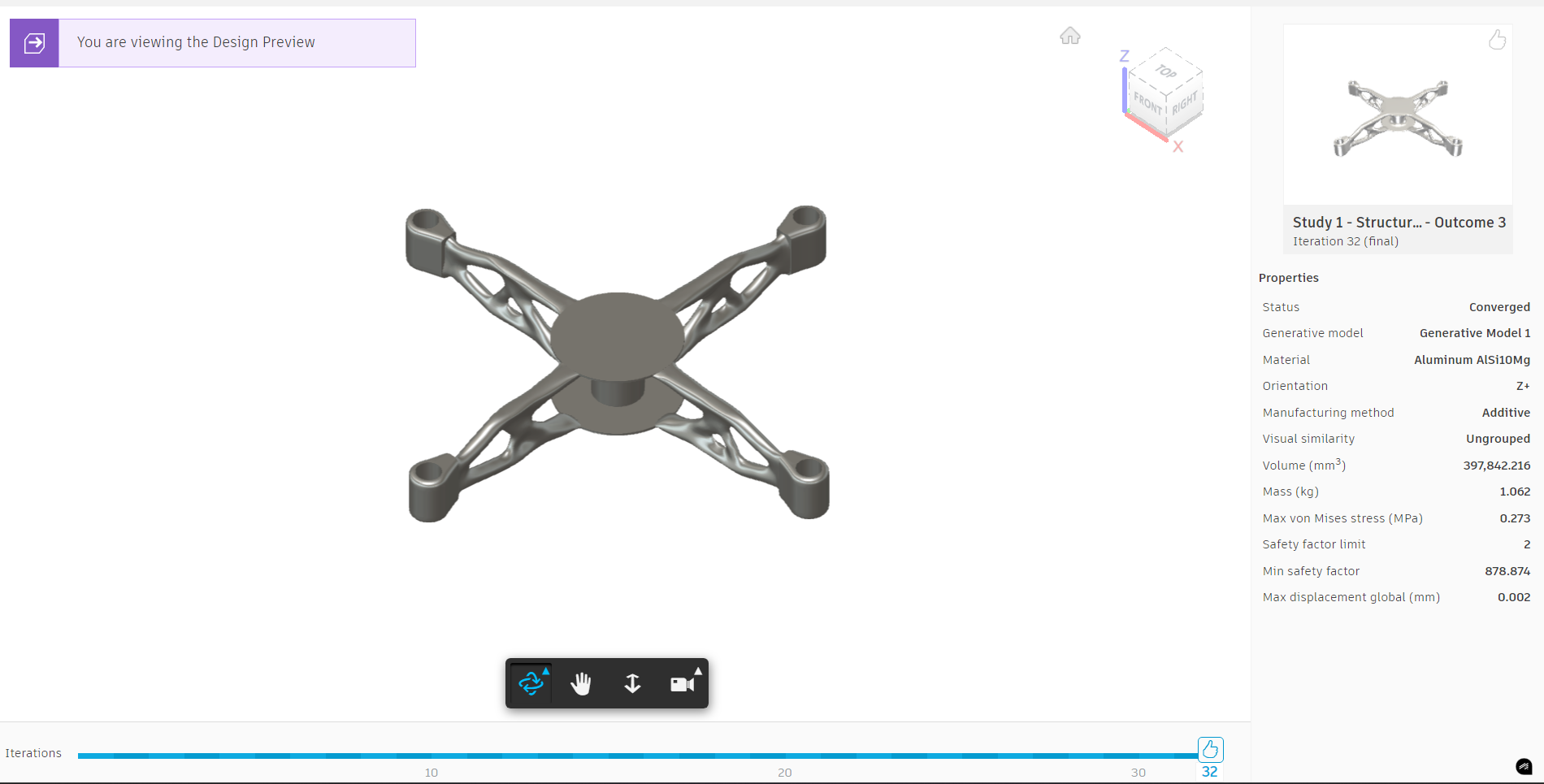
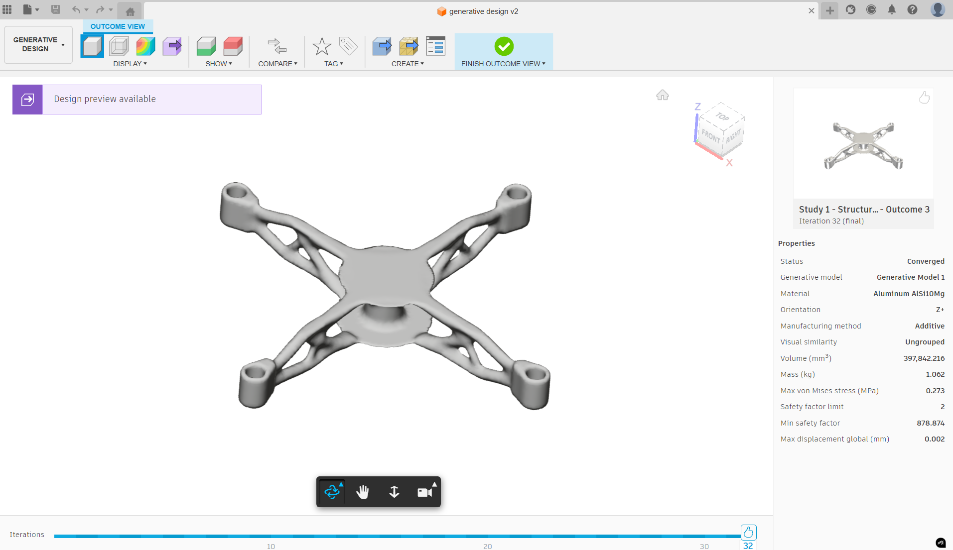
In my 3rd task, I started by creating a basic model of the drone, defining its structure, and inputting specific parameters like weight, strength, and material constraints. Using the Generative Design tools in Fusion 360, I explored various design alternatives generated by the software. These designs were optimized for performance and efficiency, considering factors like structural integrity and material usage. The process helped me understand the power of- Generative design
- Obstacle geometry and
- Preserve geometry
Here is my final generative design of drone
TASK 3: Piston and crankshaft mechanism
This task was quite different from others I’ve done before, and definitely a little tougher. It involved designing, manufacturing, and analyzing a piston and crankshaft mechanism. First, I had to design each component — the crankshaft, connecting rod, piston, and others — in Fusion 360, making sure all dimensions were accurate and realistic.
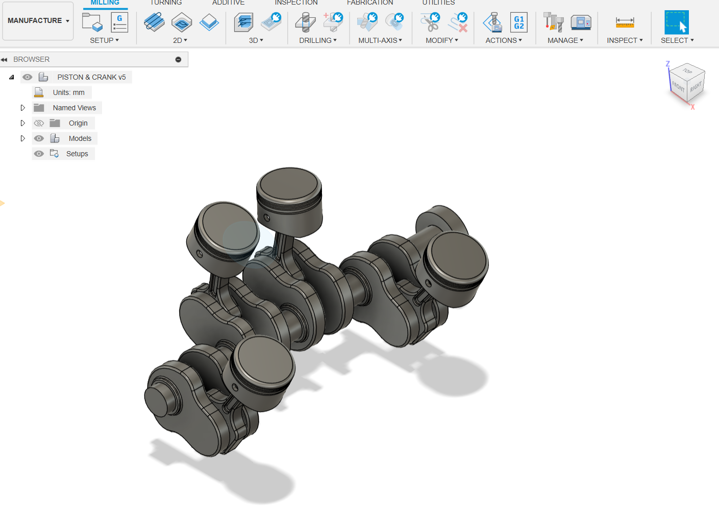
Once the components were designed, I moved on to assembling them in Fusion 360. I had to ensure that the parts fit together properly and functioned as they would in a real-world engine. However, this part of the process wasn’t without challenges. I faced some difficulties when it came to applying the right joints and ensuring smooth motion between the piston and crankshaft. I had to experiment a bit with different joint types and placements to get the movement right, and this took some time to figure out.
One of the biggest takeaways from this task was learning how to generate G-code/NC code using the CAM feature in Fusion 360. I’d never worked with generating machining code before, so this was a new and exciting skill for me. It felt great to not just design the components, but also prepare them for manufacturing.
"G-code is a language used to control CNC (Computer Numerical Control) machines. It provides instructions to the machine on how to move, cut, and shape materials during the manufacturing process."- Despite the challenges, I felt really satisfied when I finally got everything working. Seeing the piston and crankshaft mechanism operate in the simulation was a rewarding moment. Overall, this task taught me a lot about the design, assembly, motion simulation, and CAM processes, and I feel like I’ve gained a solid foundation in those areas.
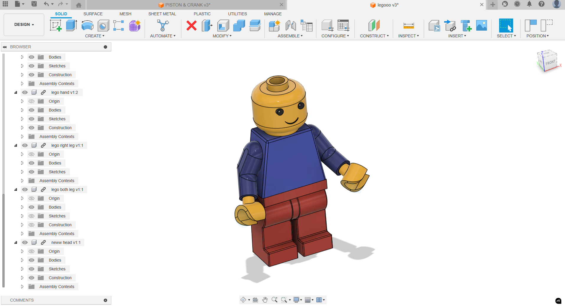
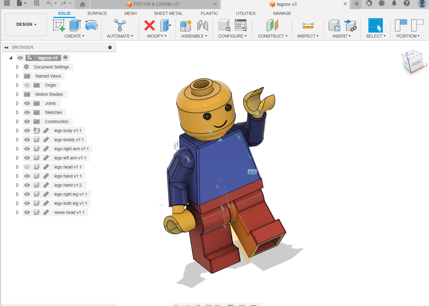
TASK 4: Animation and rendering
This task was one of the most interesting ones for me, especially since I started at Level 2. It involved designing a Lego structure in Fusion 360 and animating it using motion studies, which was both challenging and rewarding. The process not only gave me a chance to build something fun but also pushed me to explore Fusion 360's more advanced features. Design Lego Structure:
- Model Lego bricks and create the structure. Animate Using Motion Studies:
- Use Fusion 360's Animation workspace to animate the Lego man and Lego structure. Rendering with Sunset Effect: Apply materials, textures, and set up sunset lighting and shadows.
Final Render:
Render the scene using high-quality settings and make any post-processing adjustments.

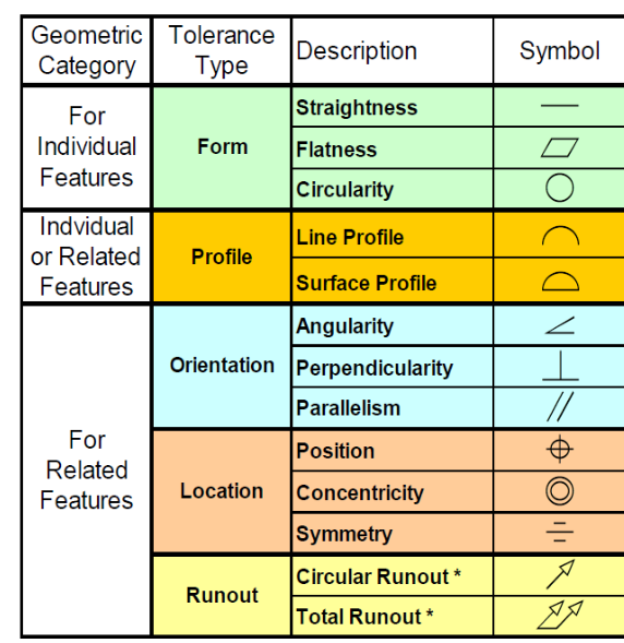
TASK 5: Geometric Dimensioning and Tolerancing (GD&T)
Geometric Dimensioning and Tolerancing (GD&T) is a system used in engineering drawings and computer-aided design (CAD) that communicates the allowable variations in the geometry of a part or assembly. GD&T provides a clear and consistent way to specify the shape, size, and location of features on a part and how those features interact with one another.
- GD&T is a symbolic language used to define the allowable variation in part geometry.
- We apply GD&T in the 2D drawing of the part, specifying tolerances for features like holes, flatness, position, and perpendicularity.
- Using GD&T ensures that parts fit together and function as intended, even with small variations during manufacturing.*
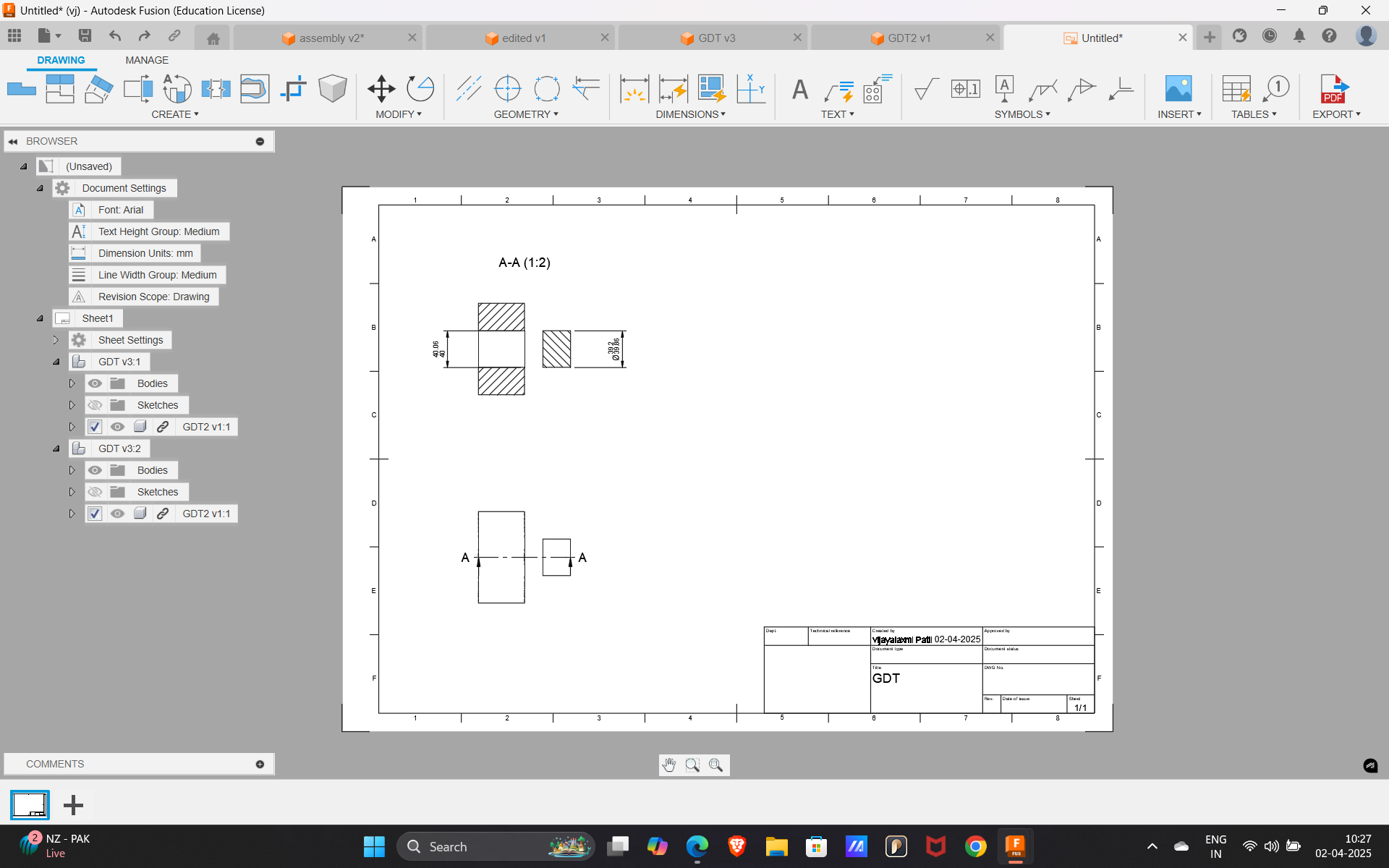
- I designed a simple 3D model in fusion 360 and then created a 2D drawing based on that model. In the 2D drawing, I applied Geometric Dimensioning and Tolerancing (GD&T) to specify the allowable variations for different features of the part. This included adding dimensions for things like hole sizes, surface flatness, and the positioning of features. I used GD&T symbols to control things like the flatness of surfaces, the diameter of holes, and the positioning of the holes relative to certain reference points (datums).
- For example, I used the diameter symbol (Ø) to specify the tolerance for hole sizes and flatness tolerance to ensure certain surfaces are within a specific flatness range. Additionally, I used position tolerance to control the exact location of the holes and ensure they align correctly.
TASK 5: Introduction to laser engraving
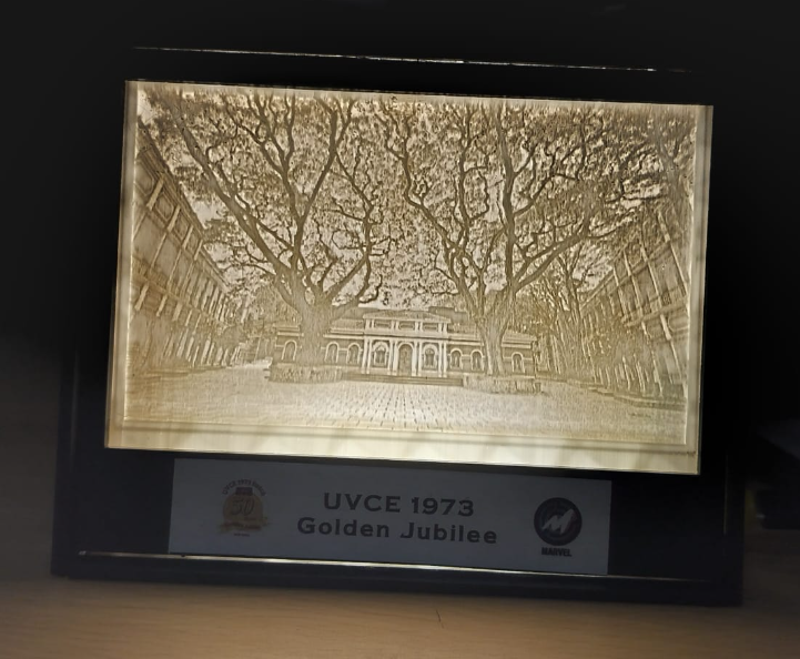
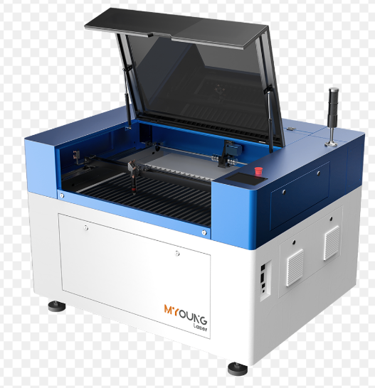
Laser engraving is a process that uses a focused laser beam to etch or mark a design, pattern, or text onto a material's surface. It works by using high-powered lasers to burn or vaporize the material, creating permanent marks. Unlike traditional engraving, which may involve tools physically cutting into the material, laser engraving is a non-contact process, meaning there is no physical force applied to the material.
- Design Creation
- Material Preparation
- Material Selection: Choose the material you want to engrave, which could be wood,metal, glass, leather, plastic, or even stone.
- Cleaning: Ensure the surface of the material is clean and free of dust, this ensures a clearer and more precise engraving.
- Securing the Material: The material needs to be placed securely on the laser engraving bed
- Setting the Laser Parameters Power Speed and Frequency
- Engraving Process
- Laser Beam Activation
- Material
- layer-by-Layer Process
- Cooling/Finishing
- Post-Engraving Cooling
- Cleaning the Surface
- Finishing Touches To operate a laser engraving machine for both engraving and cutting, specialized software is used to control the machine, manage design files, and optimize the settings. The software used can vary depending on the brand and type of laser machine, but here are some commonly used software programs:
- LightBurn
- RDWorks
- CorelDRAW4.
- Adobe Illustrator
- LaserGRBL 6.LightObject Laser Software
- LaserCAD 8.Trotec JobControl
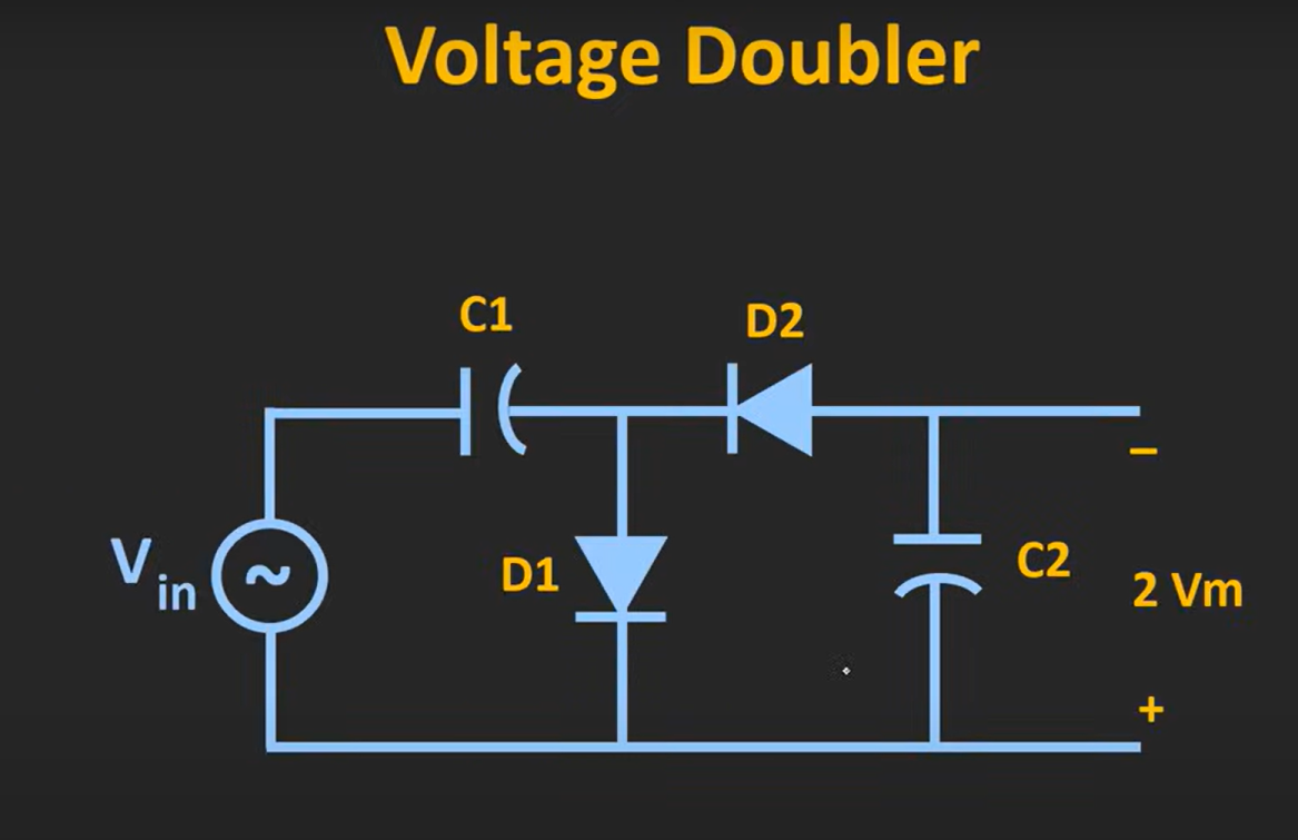
Electronics
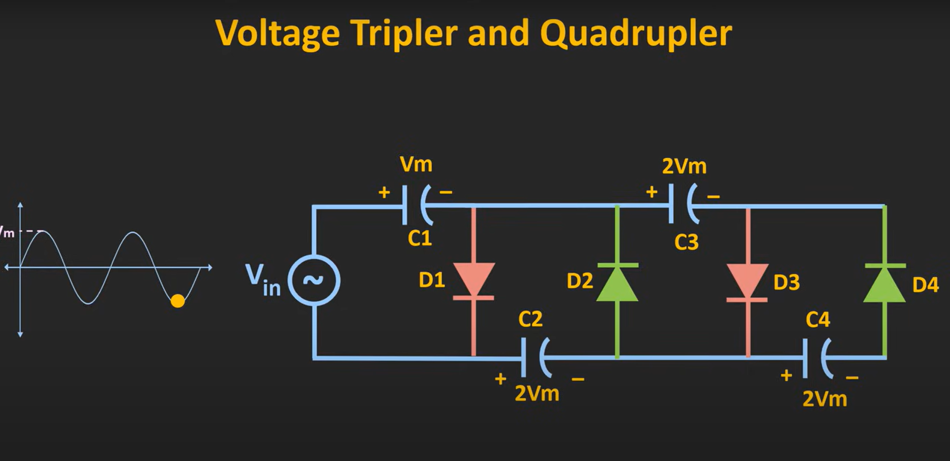
A Voltage Multiplier
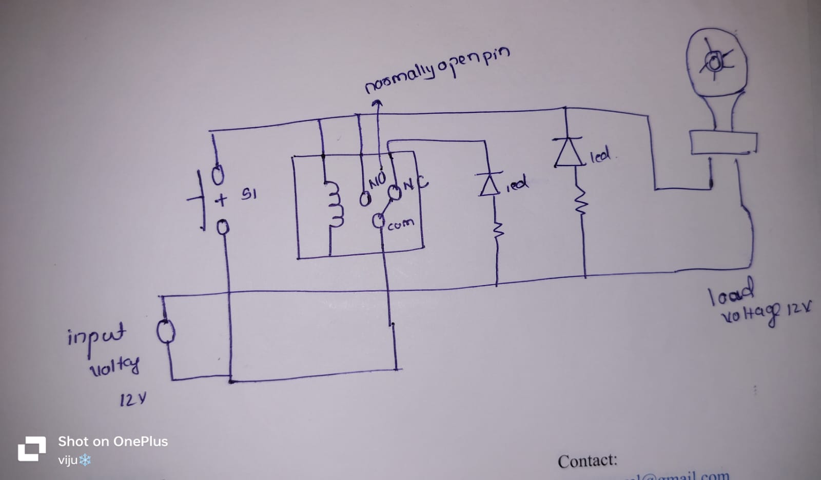
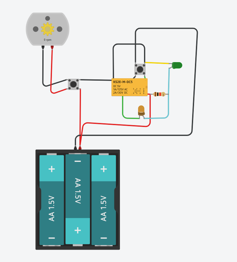
###circuit that provides short-circuit protection
Matlab