
Satish's EV-RE Level 02 Tasks :
27 / 5 / 2026
Task 1 - Point Turn of a Vehicle with Ultrasonic Sensor(Embedded)
Objective:
To design and prototype an automated safety mechanism that detects physical obstacles in real-time and halts a moving system to prevent collisions.40khz
Learnings:
Understanding time-of-flight (ToF) principles for distance measurement. Interfacing digital sensors with microcontrollers. Translating sensor data into actionable control logic (conditional programming). Prototyping control circuits using breadboards and indicator components.
General Working:
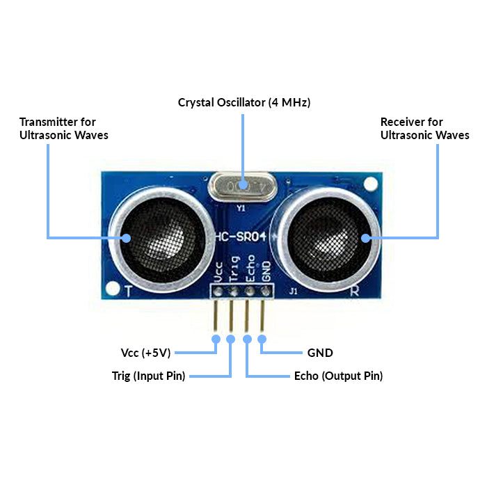
The HC-SR04 ultrasonic sensor works on the principle of echolocation, similar to how bats navigate.
Trigger: The Arduino sends a short 10-microsecond HIGH pulse to the sensor's TRIG pin.
Emission: The sensor emits a burst of 8 ultrasonic pulses at 40 kHz from its transmitter (the "speaker" cylinder).
Reflection: These sound waves travel through the air. If they hit an object, they bounce back.
Echo: The receiver (the "microphone" cylinder) detects the reflected wave. The sensor's ECHO pin outputs a HIGH pulse. The duration of this HIGH pulse is exactly equal to the time it took for the sound wave to travel to the object and back.
Calculation: The Arduino calculates the distance using the speed of sound in air (approximately 343\ m/s, or 0.0343\ cm/\mu s). Because the sound travels to the object and back, the time must be divided by two. [DISTANCE = (SPEED * TIME)/2]
A crystal oscillator is used to generate a stable and accurate frequency signal.
Real-Life Applications:
Automotive Parking Assist: The beeping sensors on the bumpers of modern cars that warn drivers of objects while reversing. Autonomous Robotics: Obstacle avoidance systems in automated guided vehicles (AGVs), drones, and robot vacuum cleaners (like Roombas).
Industrial Automation: Non-contact level sensing to measure how full a tank of liquid or grain is.
Smart Automation: Automatic doors or smart trash cans that open when a person approaches.

video link
Task 02-Temperature Detection
Objective:
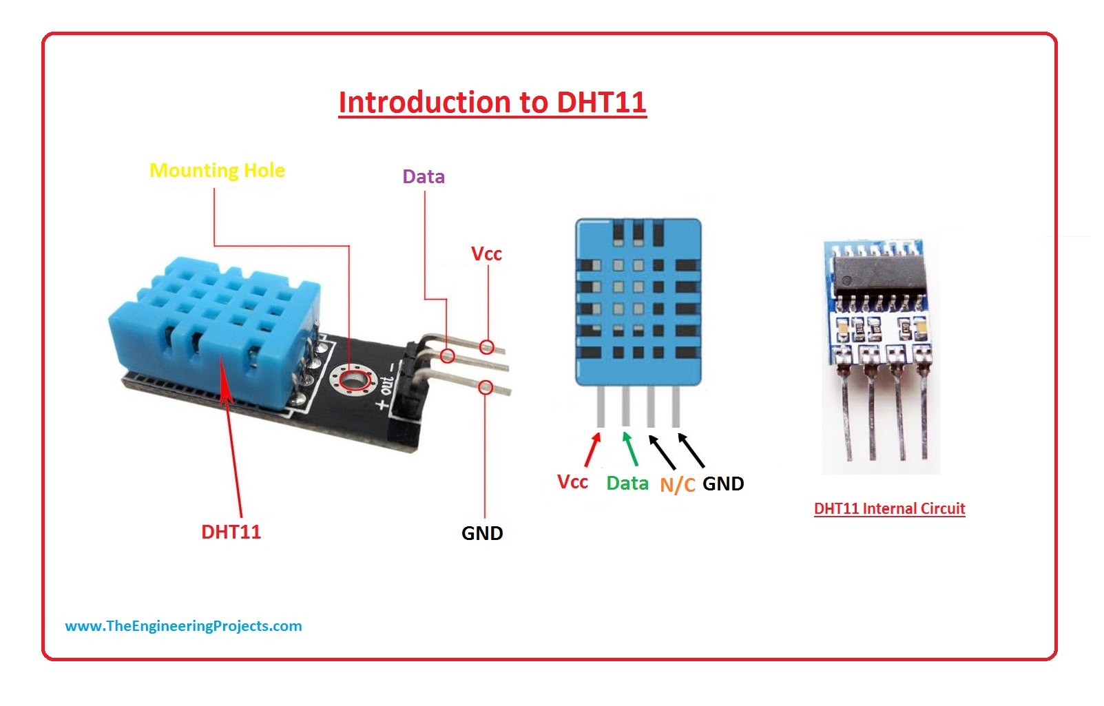
Measure temperature using an DHT11 temperature sensor and Arduino and display it on the serial monitor, taken at intervals of 1 second.
Learning:
Understood how to interface a digital temperature sensor with Arduino.
Learned the working principle of the DHT11 sensor.
Gained knowledge about digital data communication using a single data pin.
Learned how to use sensor libraries in Arduino IDE.
Understood how to read and display temperature values on the Serial Monitor.
General Working:
Humidity Measurement (Capacitive Method)
Inside DHT11, there is a capacitive humidity sensor.
It has two electrodes with a moisture-holding substrate between them.
When humidity in air changes, the capacitance changes.
The internal chip measures this capacitance change and converts it into humidity (%RH).
Temperature Measurement (Thermistor Method)
It uses an NTC thermistor.
NTC = Negative Temperature Coefficient.
When temperature increases, resistance decreases.
The internal circuit measures resistance change and calculates temperature.
Real life applications
- Weather Monitoring Systems
Used in small weather stations to measure room temperature and humidity.
- Home Automation Systems
Controls fans, air conditioners, and humidifiers automatically based on temperature.
- Smart Agriculture
Monitors greenhouse temperature and humidity for better crop growth.
sampling rate of 1Hz 0-50 degree below the case 8 bit microcontroller for data prossessing NTC Thermistor

https://youtu.be/RpIGuMP1f2E video link
Task 03-BLDC Motor And Hall Effect Sensor
Objective:
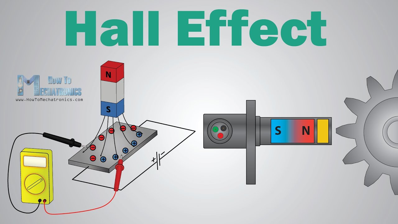
Measure the speed of a BLDC motor using a hall effect sensor and display it on the serial monitor.
Learning:
The hall effect is a relationship between electric and magnetic fields through a semiconductor that allows electricity to flow when a magnetic field is applied within the vicinity of a given hall sensor.
1. Industrial Automation
Applications Conveyor belts Robotic arm CNC machines (low-power axes) Hall sensor role Position feedback Speed control Direction detection
2. Electric Vehicles (EVs & E-Bikes)
Applications Hub motors in e-bikes Traction motors in EVs Electric scooters Hall sensor role Detects rotor position Enables smooth startup from zero speed Controls acceleration & regenerative braking


https://youtube.com/shorts/-JUJ4ZsNklA?feature=share video link
TASK 04-BATTERY CHARGING
objective:
By using solar panel we'll try to charge Li-ion battery.
components:
solar panel. Diode. TP4056. Li-ion battery holder.
working:
A TP4056 is a battery charging module that handles battery charging efficiently and safely.For the working part, when we place the solar panel under direct sunglight with the help of multimeter we can check that there is an increase in the voltage and vice versa. the diode is here used to protect both the battery and solar panel by preventing the backflow of current when the solar is under dim light or duirng night time, not generating any power.
About TP4056
it safely charges:
-
3.7V Li-ion battery
-
18650 battery
-
Li-Po battery
It protects the battery from:
-
Overcharging
-
Excess current


TASK 05-solar Tracker using LDR and servo motor.
objective:
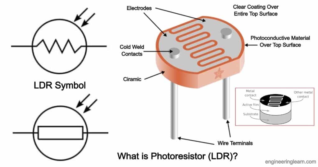
The goal of this project is to design and implement a light-tracking system that automatically aligns a solar panel toward the strongest light source. This is achieved using an Arduino, a servo motor, and two LDRs (Light Dependent Resistors). The system improves solar panel efficiency by ensuring it always faces the most intense light direction.
working
Two LDRs placed on opposite sides of the solar panel detect the light intensity difference.
If LDR1 > LDR2, it means light is stronger on one side → servo rotates panel in that direction.
If LDR2 > LDR1, it rotates the other way.
If light levels are similar, no movement occurs.
Learnings:
LDR is nothing but a light dependent resistance. The servo motor successfully rotates the solar panel toward the brighter light source.
The system responds in real-time to changes in light, such as moving a flashlight or the sun’s path.
The project demonstrates the practical use of sensors, actuator control, and basic embedded systems for energy optimization.
Density of light falling in LDR is measured in "LUX". More the desity of light less the resistance and vice versa. It is a pasive component.

https://youtu.be/qkZWQGHKUZo video link
Task 06-Simple Electric Circuits Simulation on MATLAB(Power Electronics)
Objective:
-
To simulate a sine wave input signal using LTspice.
-
To apply gain using an amplifier block.
-
To observe input and output waveforms using waveform viewer.
-
To understand the effect of gain on signal amplitude.
-
To verify theoretical results using simulation.
Learnings:
-
Draw and connect circuit components in LTspice.
-
Use voltage source to generate sinusoidal waveform.
-
Apply simulation commands (Transient Analysis).
-
Observe and compare input and amplified output signals.
-
Analyze amplitude change due to gain factor.
-
Interpret waveform graphs correctly.
-
Understand practical behavior of analog circuits before hardware implementation.
Special learning of LTspice:
-
Can simulate 100s of components and check the expected output.
-
High-speed SPICE simulation engine.
-
Large built-in component library (diodes, BJT, MOSFET, op-amps).
-
Accurate analog and power electronics simulation.
-
Easy waveform plotting and analysis tools.
Drawback of LT
-
LTspice is mainly designed for analog circuits. It is not suitable for complex digital or embedded system simulation.
-
No PCB Design Integration Unlike tools such as Altium Designer or Proteus, LTspice does not support PCB layout design.

Task 08-Automatic night lamp for EVs
Objective:
To construct an automated headlight setup, using a transistor and a LDR (Light dependent resistor).
Working:
An automatic night lamp works based on the intensity of light in the surroundings. In this project, an LDR (Light Dependent Resistor) is used to detect ambient light. The resistance of the LDR changes according to light intensity — it has low resistance in bright light and high resistance in darkness.
The LDR is connected in a voltage divider circuit and interfaced with an Arduino Uno. The Arduino continuously reads the analog voltage value from the LDR.
When it is daytime (bright light) → LDR resistance is low → Arduino detects higher light intensity → Lamp remains OFF.
When it is night (darkness) → LDR resistance increases → Arduino detects low light intensity → Lamp turns ON automatically.
The Arduino controls an LED (or a bulb through a relay) based on a predefined threshold value in the program. Thus, the system automatically switches the lamp ON at night and OFF during the day without manual intervention.

https://youtu.be/Zcfbi1tbC14 video link
Task 09-Buck Converter on LTspice (Power Electronics)
Objective:
The objective of this experiment is to design and simulate a Buck Converter using LTspice in order to step down a DC input voltage to a lower DC output voltage. The experiment aims to study the working principle of a DC-DC step-down converter, analyze switching operation using a MOSFET, and observe important waveforms such as inductor current, output voltage, and switching pulses. It also helps in understanding voltage regulation and efficiency through simulation before practical implementation.
Learning:
After completing this experiment, we understand the operating principle of a Buck Converter and its role in DC-DC power conversion. We learn how to design and simulate power electronic circuits using LTspice and analyze transient responses and steady-state waveforms. We gain knowledge about the function of components such as MOSFET, diode, inductor, and capacitor in voltage step-down operation. We also understand the relationship between duty cycle and output voltage and develop the ability to evaluate converter performance through simulation results.
Task 10-Wireless Charger Simulation on Tinkercad (Power Electronics)
Objective:
-
To design and simulate a basic wireless power transfer system.
-
To generate a PWM signal using Arduino Uno.
Working:
In this experiment, the Arduino Uno generates a PWM signal which is applied to the inductor coil. The switching PWM signal creates a continuously changing magnetic field around the coil. When a receiver coil is placed near the transmitter coil, this changing magnetic field induces a voltage in the receiver coil due to electromagnetic induction (Faraday’s Law). The induced voltage is then used to power a load such as an LED. Thus, electrical energy is transferred wirelessly without any physical connection between transmitter and receiver.
Faraday’s Law states that:
Whenever the magnetic flux linked with a conductor changes, an electromotive force (EMF) is induced in the conductor.
Learning:
-
Understand the principle of wireless power transfer (electromagnetic induction).
-
Understand how energy is transferred from transmitter coil to receiver coil.
-
Analyze the effect of PWM duty cycle on power transfer.
-
Gain practical knowledge of basic wireless charging systems.

Task 11-Utilizing Transistors as Switches and Voltage Regulators (Power Electronics)
Objectives:
To study the operation of a transistor as an electronic switch.
To understand the working of transistor in cutoff and saturation regions.
To control an LED load using a transistor switch.
To analyze base current and collector current relationship.
To understand how a transistor can regulate voltage in simple circuits.
Working:
When we place a transistor in between a battery and a bulb or LED.The LED will not light up, but as soon as we give a volatge supply either positive or negative the LED will start to blink. Note that for the transitor to work the voltage should be minimum 0.6 - 0.7V.
.jpeg?raw=true)

https://youtu.be/qXjibxnsJqI Link for video
Task 12-LED Brightness Control Using PWM and MOSFET (Power Electronics)
Objective:
The objective of this experiment is to control the brightness of an LED using the