
Parthjit singh
Task 1 - LTspice and KiCad
Objective: Design and simulate an astable multivibrator using 555 timer, and also be familiar with LT Spice & KI Cad.
A multivibrator is an electronic circuit designed to produce square wave signals and is used in many timing and switching applications. It works in three main modes:
1. Astable Multivibrator
- Stability: Least stable – it continuously switches between HIGH (1) and LOW (0) states on its own, without any external trigger.
- Working: It automatically generates a continuous pulse or square wave.
- Use: Commonly used for blinking LEDs or as a basic clock pulse generator.
2. Monostable Multivibrator
- Stability: Has one stable state.
- Working: Requires a single trigger to switch states. It stays in the new state for a fixed period and then returns to its original state automatically.
- Use: Used in timer circuits like delay timers or pulse generators.
3. Bistable Multivibrator
- Stability: Most stable – has two stable states.
- Working: Needs two separate triggers – one to switch to the other state and another to reset it.
- Use: Ideal for memory storage or to control automatic devices like headlights when connected to an LDR (Light Dependent Resistor).
Also, in all these circuits, the timing and pulse width (duty cycle) can be adjusted by changing the resistor values.
Task 2 - Temperature Detection
Objective: Measure temperature using an LM-35 temperature sensor and Arduino and display it on the serial monitor, taken at intervals of 5 seconds and turn a led on using BJT as a switch when the temp crosses a certain threshold (40°C).
Learning Summary in Own Words:
The LM35 is an analog temperature sensor made by Texas Instruments. It’s designed to measure temperature and convert it into an electrical signal.
Key Specifications:
- Working Voltage: 4V to 30V
- Current Consumption: Very low, around 60µA during operation
- Temperature Range: -55°C to +155°C
- Accuracy: Around ±0.5°C at room temperature
- Note: To measure temperatures below 0°C, the LM35 needs a negative voltage. Instead, the TMP36 sensor is recommended, as it can measure negative temperatures without needing a negative bias.
How It Works:
The LM35 outputs a voltage that changes directly with temperature. For every 1°C rise, the output increases by 10mV (0.01V). For example, at 25°C, it will give about 0.25V. In a typical setup, when the temperature goes above 40°C, the circuit activates an LED, turning it ON.
Circuit Connections:
LM35 to Arduino UNO:
- GND → GND
- VS (Power) → 5V
- Vout (Signal) → A1
BJT (Transistor) to Arduino UNO:
- Base → Pin ~9 (PWM)
- Emitter → GND
- Collector → LED negative (-)
- LED positive (+) → 5V
This setup allows the LED to turn on automatically when the LM35 detects a temperature higher than 40°C.
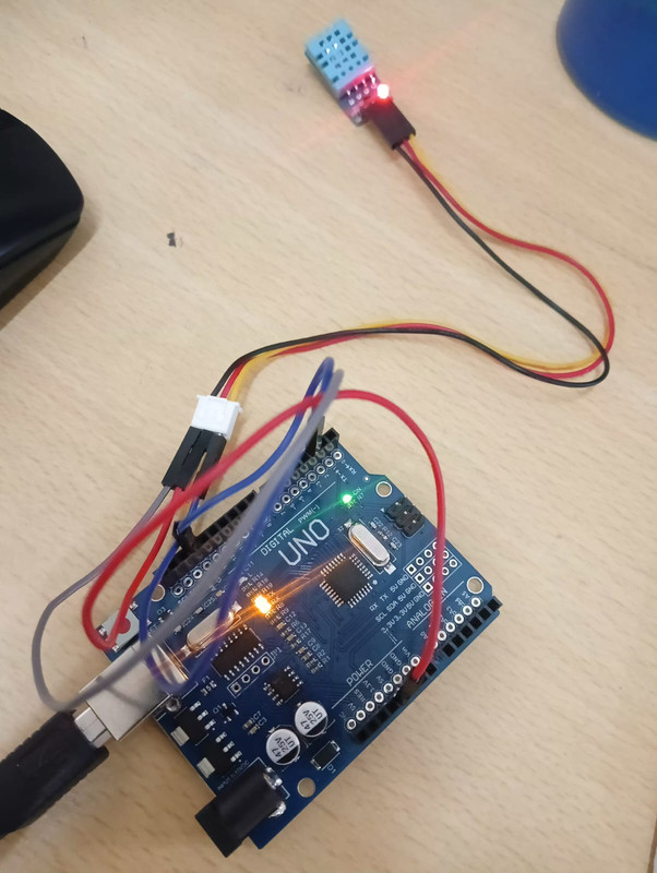
TASK 3: Temperature and Humidity Detection
Objective: Measure temperature and humidity using DHT11 and display the readings on serial monitor.
The DHT11 is a digital sensor used to measure both temperature and humidity. It sends a digital signal that can be read using the digital pins of an Arduino, making it more accurate than analog sensors.
Key Features: Full Form: DHT = Digital Humidity and Temperature sensor
Temperature Range: 0°C to 50°C with ±2°C accuracy
Humidity Range: 20% to 80% relative humidity (RH)
Output Type: Digital
Internal Structure: Contains a 14-pin, 8-bit microcontroller
Power Supply: Works on 3.3V to 5.5V
DHT11 vs DHT22: Feature DHT11 DHT22 Humidity Range 20–80% RH 0–100% RH Temperature Range 0°C to 50°C (±2°C) -40°C to 80°C (±0.5°C) Sampling Rate 1 reading per second 1 reading every 2 seconds Accuracy & Speed Less accurate but faster More accurate but slower
Note: DHT22 provides more precise data but updates more slowly compared to DHT11.
How It Works: a. Humidity Sensing: The sensor has a special moisture-sensitive material. When it absorbs water vapor, it releases ions that change the resistance between internal electrodes. This resistance change is processed by the sensor's internal IC to calculate humidity.
b. Temperature Sensing: The sensor uses a thermistor, a component whose resistance decreases as temperature increases (negative temperature coefficient). The IC reads this resistance change and converts it into temperature data.
Circuit Connections with Arduino UNO: DHT11 Pin Arduino Pin VCC (Power) 5V DATA (Signal) Digital Pin 7 GND GND
This setup allows the Arduino to receive temperature and humidity data from the DHT11 sensor through a digital pin.
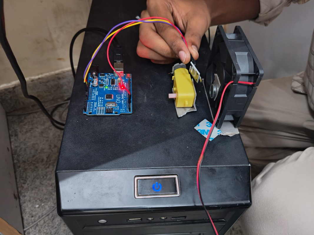
Task 4- BLDC Motor And Hall Effect Sensor
Objective: Measure the speed of a BLDC motor using a hall effect sensor and display it on the serial monitor.
The Hall effect describes how a magnetic field can influence the flow of electricity in a semiconductor. When a magnet comes near a Hall sensor, it causes a small voltage change, which can be detected. This property allows the Hall sensor to detect the presence of a magnetic field—and in the case of rotating motors, this can be used to count revolutions.
By placing a Hall sensor near a rotating BLDC motor (with magnets or magnetic poles), we can measure how many times the magnetic field passes the sensor in a second, which gives us the rotational speed of the motor.
Circuit Connections: Hall Sensor (A3114) → Arduino UNO
GND → GND
Vcc → 3.3V
Data → Digital Pin 2
BLDC Motor → Arduino UNO
GND → GND
Vcc → 5V
Once the connections are made, the Hall sensor detects every time a magnet (attached to the BLDC motor's shaft) passes by. The Arduino reads this data through pin 2 and calculates the motor speed, which is then shown on the serial monitor.
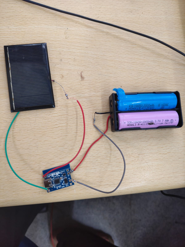
Task 5 - Battery Charging
Objective: Charge the Li-ion battery using solar panels.
General Working – In Own Words:
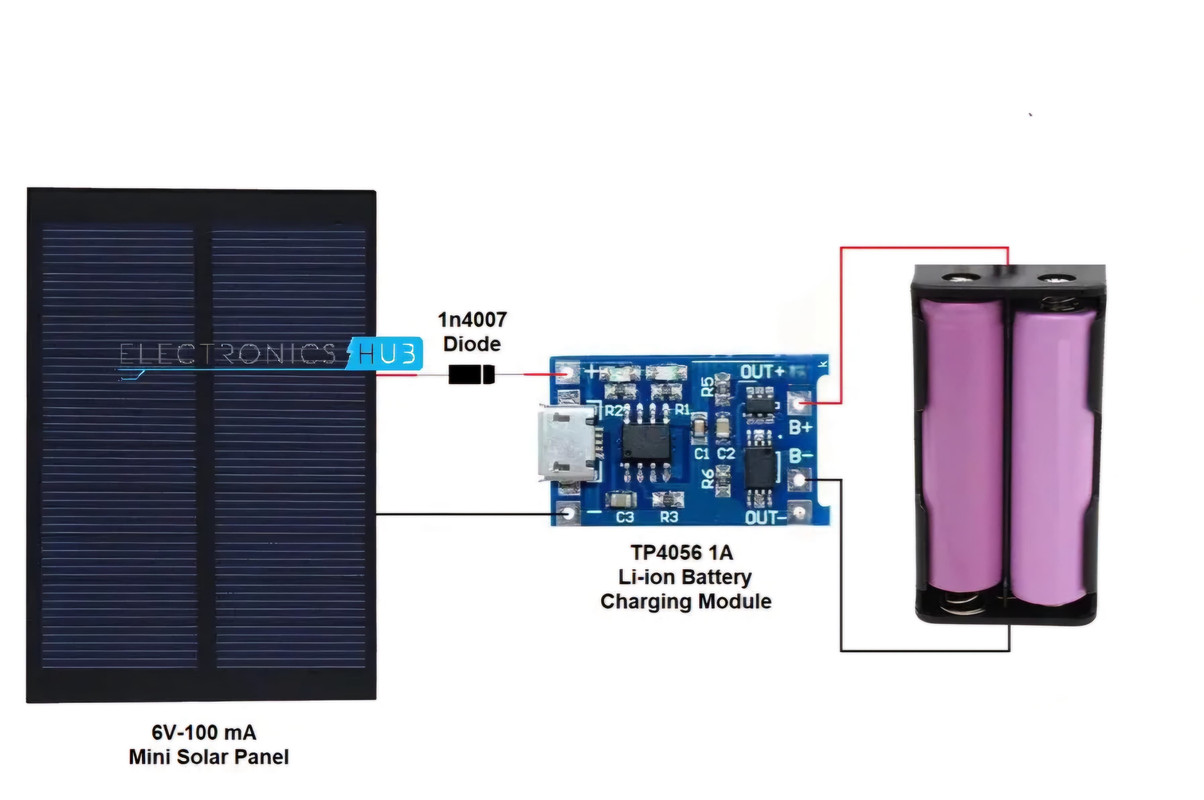
When the solar panel is exposed to sunlight, it generates DC voltage, which is used to charge a Li-ion battery. To ensure the battery charges safely and properly, a TP4056 charging module is used. This module controls how much voltage and current flows into the battery, protecting it from overcharging or damage.
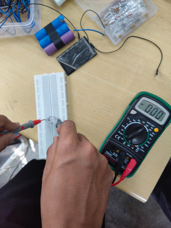
A multimeter can be used to check the output voltage from the setup.
To prevent electricity from flowing in the wrong direction (from the battery back into the solar panel when sunlight is weak or absent), a 1N4007 diode is added. This diode blocks any reverse current, helping to protect both the battery and the solar panel from damage and power loss.
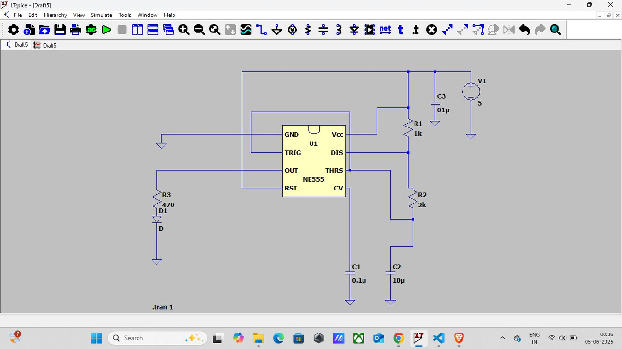
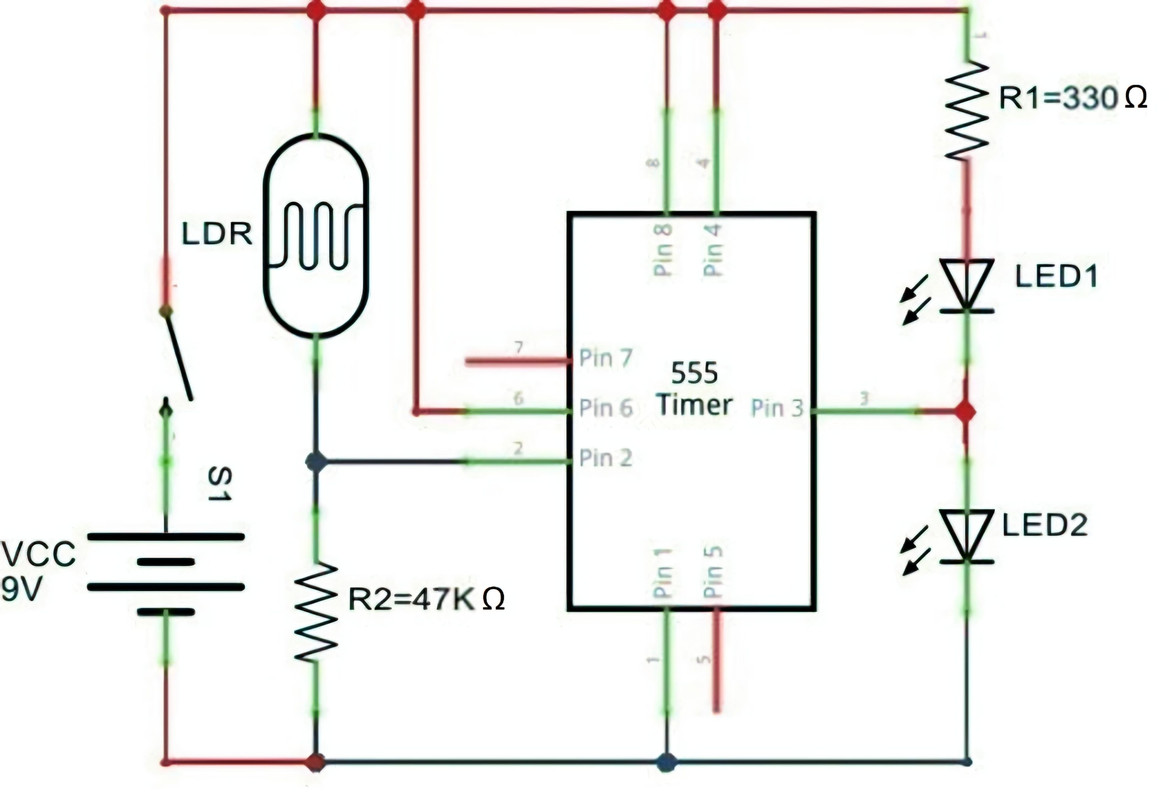
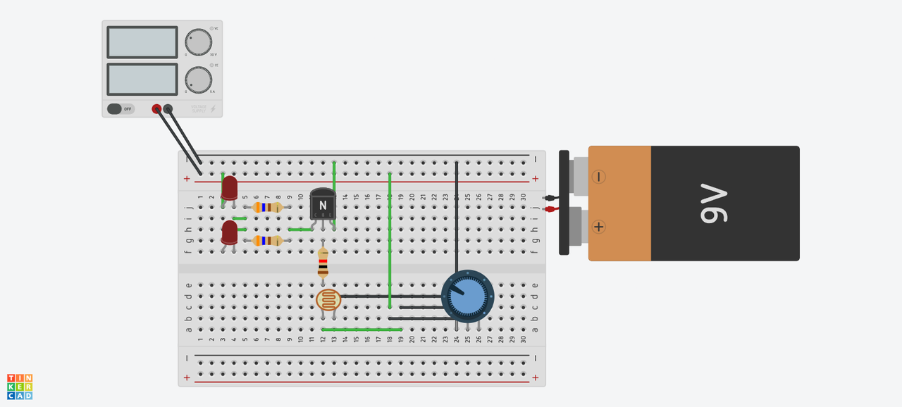
Task 6 - 555 Timer & LDR
Objective: Construct an automated headlight setup, using an NE555 (IC1) and a LDR (Light dependent resistor).
Learning & Working – In Own Words:
An LDR (Light Dependent Resistor) is a special type of resistor whose resistance changes based on the amount of light falling on it. When there is no light, the LDR has a very high resistance (around 1 Mega Ohm), and when there is bright light, its resistance becomes very low (around 5 Kilo Ohm).
This behavior makes the LDR useful for detecting light levels in circuits.
A 555 Timer IC is often used along with the LDR to control the circuit’s response based on light conditions—such as turning a light on or off automatically.
There is an inverse relationship between light intensity and resistance:
- As light intensity increases, the resistance decreases
- As light intensity decreases, the resistance increases
This can be summarized as: I ∝ 1/R Where:
- I = Light Intensity
- R = LDR Resistance
Task 7 - Solar Panel
Objective: Make a simple solar panel set-up using diodes.
Learning – In Own Words: In this task, we used 1N4148 diodes (also known as signal diodes) as a replacement for solar panels to generate a voltage output from sunlight. These diodes work mainly in forward bias and are commonly referred to as run-of-the-mill diodes because they are standard, easily available, and widely used in many electronic circuits.
To get a higher voltage output, the diodes were connected in series. This way, the voltage from each diode adds up, allowing us to produce more total voltage from the sunlight
Task 8 - Solar Tracker
Objective: Design and implement a system using servo where the solar panel follows the sun to maximize the energy absorbed by the solar panel.
A solar tracker is a system designed to automatically adjust the position of a solar panel so that it always faces the sun, maximizing the amount of sunlight it receives throughout the day.
To achieve this, it uses a servo motor, which is a specialized motor known for its precise control over angular or linear movement. Unlike regular motors that rotate continuously, a servo motor can rotate to a specific angle and hold that position accurately. This makes it ideal for solar tracking systems, where small, controlled movements are needed to follow the sun’s path across the sky.
By using sensors (like LDRs) to detect the sun's position and a servo motor to adjust the panel accordingly, the solar tracker ensures maximum efficiency and energy output from the solar panel.
![]()
![]()
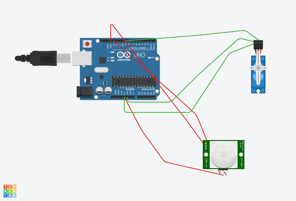
Task 9 - Automatic Door Opening System
Objective: An automated door opener system that detects individuals or objects using a PIR sensor and smoothly opens and closes the door using a servo motor, providing convenience and accessibility.
General Working – In Own Words:
A PIR (Passive Infrared) sensor is an electronic device that detects motion by sensing the infrared radiation naturally emitted by objects, especially warm bodies like humans or animals, within its view. It is widely used in applications such as security alarms, automatic lighting systems, and other areas where detecting movement is important.
Sensor Specifications:
- Detection Distance (Linear Range): 5 to 10 meters
- Detection Angle (Angular Range): 90 to 120 degrees
This means the sensor can detect motion within a certain distance and over a wide field of view.
PIR Sensor Pin Diagram:
The sensor typically has three pins:
- VCC (Power supply)
- Output (Signal)
- GND (Ground)
This setup allows the sensor to be connected easily to microcontrollers or other devices for motion detection purposes.
Task 10 - Automatic night lamp for EVs
Objective: Construct an automated headlight setup, using a transistor and a LDR (Light dependent resistor).
General Working: For this task, I utilized Tinkercad, an online circuit simulation platform, due to its similarity with Task 11. In this circuit, the transistor functions as an electronic switch that controls the LED's operation. The system works by using the Light Dependent Resistor (LDR) to detect ambient light levels - when light intensity changes, it affects the LDR's resistance, which in turn controls the transistor's switching behavior to either illuminate or extinguish the LED.

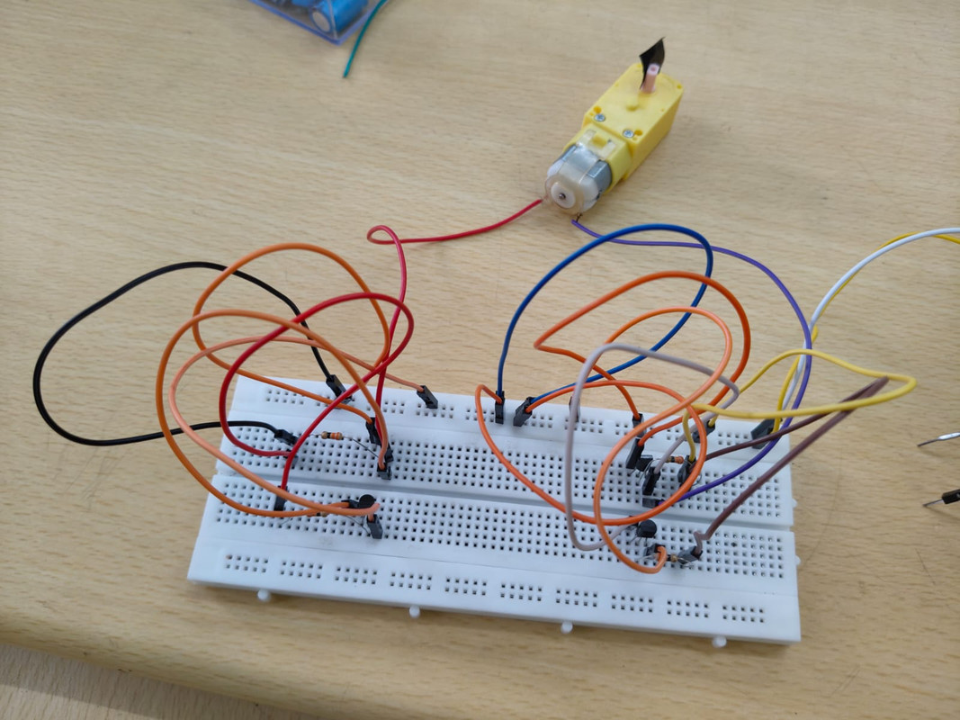
Task 11- Building a Basic H-Bridge Motor Driver using MOSFETs (Power Electronics)
objective-Building a Basic H-Bridge Motor Driver using MOSFETs (Power Electronics)
Building a Basic H-Bridge Motor Driver Using MOSFETs (Power Electronics)
An H-Bridge is an essential circuit in power electronics used to control the direction and speed of a DC motor. By using MOSFETs (Metal-Oxide Semiconductor Field-Effect Transistors), we can build an efficient and reliable H-Bridge motor driver.
🔧 Basic Concept:
The H-Bridge gets its name from the "H" shape of the circuit. It consists of four switches (in this case, MOSFETs) that control the direction of current flow through the motor.
- MOSFETs Q1 and Q4 form one diagonal pair.
- MOSFETs Q2 and Q3 form the other diagonal.
By turning on specific pairs of MOSFETs, the current can flow in either direction through the motor, making it rotate forward or backward.
⚙️ Working Logic:
| Q1 | Q2 | Q3 | Q4 | Motor Direction |
|---|---|---|---|---|
| ON | OFF | OFF | ON | Forward |
| OFF | ON | ON | OFF | Reverse |
| OFF | OFF | OFF | OFF | Stop (Free-run) |
| ON | ON | OFF | OFF or other wrong combos | ⚠️ Short Circuit – Avoid |
Note: Never turn on both MOSFETs on the same side (Q1+Q2 or Q3+Q4) — this causes a short circuit (shoot-through).
🔌 Circuit Components:
- 4 x N-channel MOSFETs (e.g., IRF540N or similar)
- 1 x DC Motor
- Power source (Battery or DC power supply)
- Control logic (Microcontroller like Arduino or manual switches)
- Flyback diodes (optional but recommended) to protect from back EMF
🔗 Connections Overview:
- Motor terminals are connected between the midpoints of the two legs of the H-Bridge.
- Power supply connected to the high side of the bridge.
- MOSFET gates are controlled via digital signals from a microcontroller or switches.
✅ Applications:
- DC motor speed and direction control
- Robotics (e.g., for wheels and actuators)
- Electric vehicles
- CNC machines
Task 12 - ultrasonic sensor
🔧 Basic Working Principle The HC-SR04 uses ultrasonic waves (sound waves beyond human hearing, typically 40 kHz) to measure distance. It works on the principle of echo ranging, similar to how bats navigate:
The trigger pin sends out an ultrasonic pulse (8 cycles of 40 kHz).
The pulse travels through the air and reflects back when it hits an object.
The echo pin receives the reflected pulse.
The time taken for the echo to return is used to calculate the distance using the speed of sound.
🔌 Pin Configuration Pin Name Function 1 VCC Power supply (+5V) 2 Trig Trigger input (start pulse) 3 Echo Echo output (receives reflection) 4 GND Ground
📐 Distance Calculation Formula Distance
Time × Speed of Sound 2 Distance= 2 Time×Speed of Sound
Speed of Sound ≈ 343 m/s or 0.0343 cm/µs
Time is the duration (in microseconds) between trigger and echo
The division by 2 accounts for the to-and-fro travel of the sound wave.
In centimeters, a commonly used formula:
Distance (cm)
Time (µs) 58 Distance (cm)= 58 Time (µs)
📏 Specifications Parameter Value Operating Voltage 5V DC Working Current 15 mA Frequency 40 kHz Measuring Range 2 cm to 400 cm (0.02 to 4 m) Accuracy ±0.3 cm Measuring Angle ~15°
🛠️ Applications Obstacle Avoidance in robots
Object Detection
Water Level Sensing
Security Systems
Automated Parking Systems
