HIREMATH SUGURESH
N CHANNEL MOSFET
N-channel MOSFETs are tiny switches controlled by voltage, not touch. Electrons flow when a positive voltage opens a channel between the drain and source. Imagine a water channel controlled by an electric field. Perfect for low-power circuits, N-channel MOSFETs are workhorses in electronics, from phones to computers. Learnt about the working of the N-Channel MOSFET from the resource link provided and made a basic design on TinkerCAD
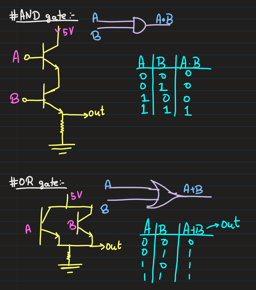
OR Gate and AND Gate Using Transistors
OR Gate: An OR gate is a digital logic gate that outputs "1" (true) if at least one of its inputs is "1". To implement an OR gate with transistors, a pair of transistors (usually NPN or MOSFETs) is connected in parallel. When either input transistor is activated, it completes the circuit, allowing current to pass through and creating a high output. This setup ensures that if either input is high, the output will be high.
AND Gate: An AND gate is a logic gate that outputs "1" only when all its inputs are "1". In a transistor-based AND gate, transistors are connected in series, meaning both need to be activated simultaneously to complete the circuit and allow current to pass. This design ensures the output is high only when all inputs are high, implementing the AND logic.
Both types of gates form the building blocks for complex circuits in digital electronics.

AND GATE TRANSISTOR
OR GATE TRANSISTOR
Filter Design
Design a second-order bandpass filter using IC741 that amplifies the signal to roughly 1.5 times the original signal. The cutoff range between 4kHz and 10kHz. (Use LTspice).
- I am new to using LTspice software,this task helped me to understand how the simulation command works for AC and DC
- I learned so many things about the amplifier and OPamps circuit