BLOG · 5/10/2024

LEVEL 3 TASK
1) Task: Chassis Design
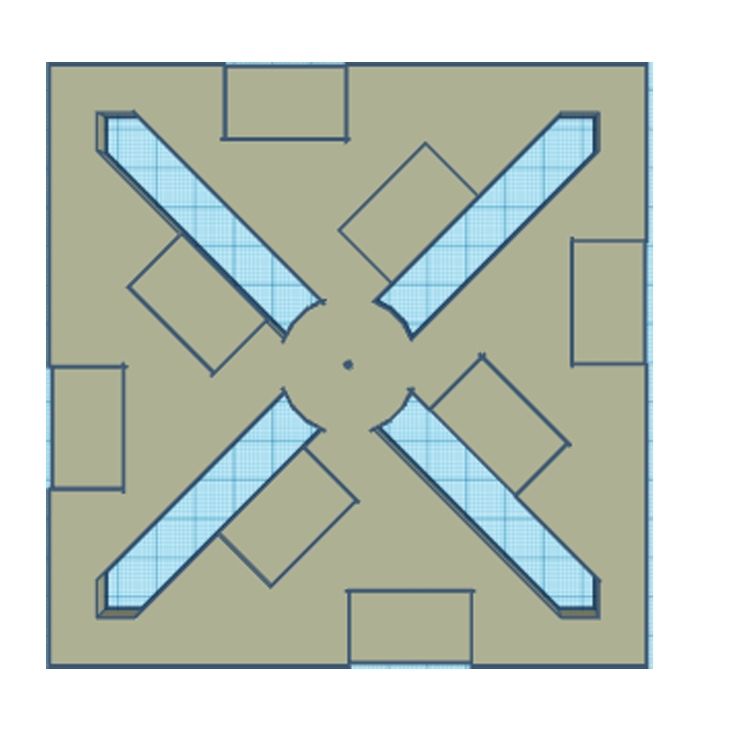
In this task, I designed a chassis for the RC car using Fusion 360 and Tinkercad, ensuring that the design would be compatible with the 3D printer available at MARVEL. Initially, I had limited experience with CAD software, but through practice, I developed a strong understanding of how to create a stable and efficient chassis. The design process involved balancing weight distribution to optimize the car’s performance during operation. I also learned how to anticipate potential issues such as stress points and how to reinforce the structure accordingly.
Key Learnings:
- Mastered basic and advanced CAD design techniques.
- Understood the importance of weight distribution in vehicle stability.
- Gained hands-on experience with 3D printing, from design to physical realization.
2) Task: SPI Communication
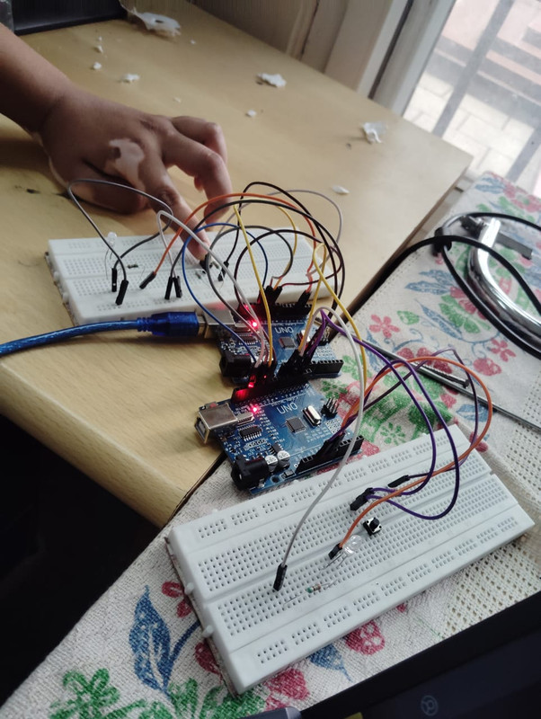
This task required setting up SPI communication between two microcontrollers, an arduino uno as the master and an another arduino as the slave. Initially, I had only a theoretical understanding of SPI, but this task allowed me to delve into the practical aspects. I learned how SPI enables simultaneous data transmission and reception (full-duplex), and how to manage the clock signal for synchronization. Troubleshooting communication errors also helped me understand the importance of correct wiring and timing.
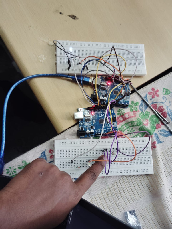
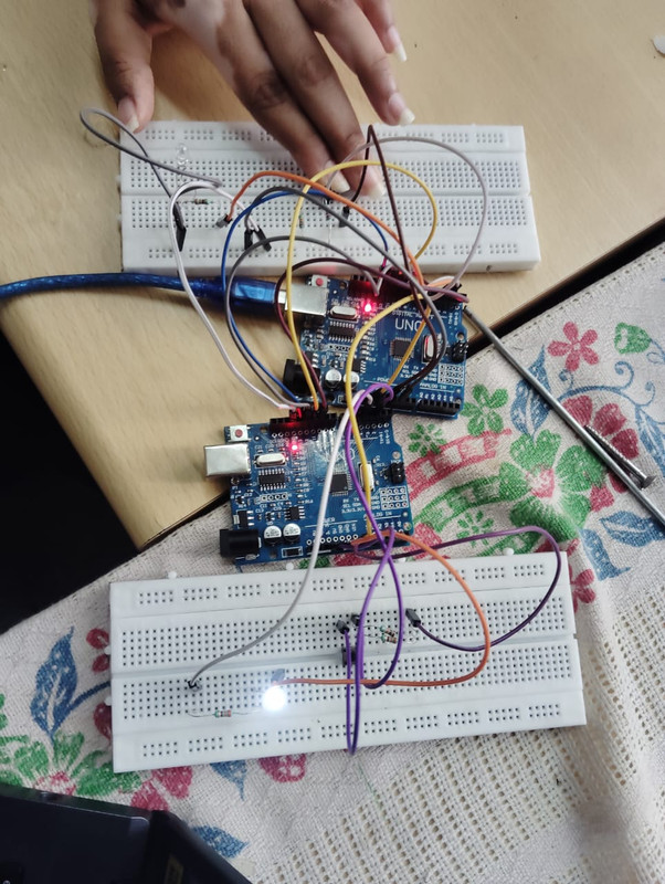
Key Learnings:
- Developed practical skills in setting up and configuring SPI communication.
- Learned to handle clock synchronization and data integrity.
- Gained experience in debugging and resolving communication issues.
3) Task: I2C Control
In this task, I implemented I2C communication to control multiple sensors connected to a single master microcontroller. I2C is more versatile than SPI because it allows multiple devices to share the same communication bus. Through this task, I learned to manage the bus addressing and understood the challenges of handling multiple slave devices. I also explored the advantages of I2C in reducing the number of pins required for communication, making it ideal for projects with limited GPIO availability.
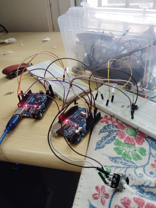
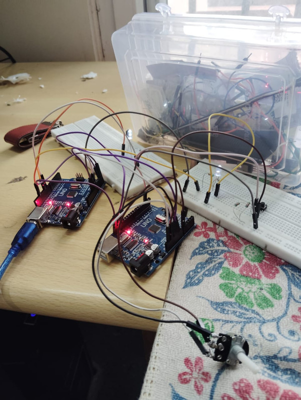
Key Learnings:
- Gained a deep understanding of I2C protocol and its applications.
- Learned to manage bus addressing and data flow in a multi-device setup.
- Improved my ability to design and implement communication systems in microcontroller projects.
4) Task: Speed Control of BLDC Motor
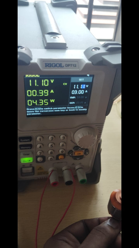
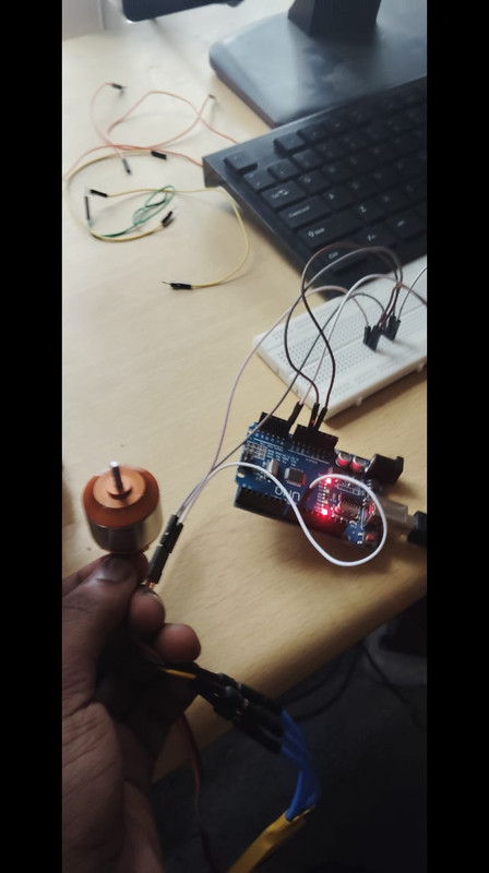
This task involved controlling the speed of a Brushless DC (BLDC) motor using a Proportional-Integral (PI) controller. BLDC motors are known for their efficiency and precision, which are critical in applications such as electric vehicles. I learned how to use a PI controller to regulate the motor's speed, providing a balance between responsiveness and stability. Observing the motor's performance on a CRO helped me understand how different control parameters affect the motor's behavior.
Key Learnings:
- Gained practical experience in motor control using PI controllers.
- Learned about the advantages of BLDC motors in high-performance applications.
- Enhanced my understanding of control systems and their implementation in hardware.
5) Task: Integration of Multiple Sensors
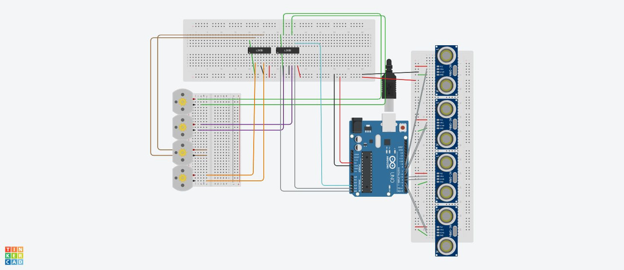
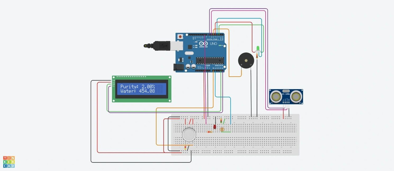
The final task was to integrate multiple sensors into the RC car, utilizing the chassis designed in Task 1. This task required combining the knowledge and skills gained from the previous tasks, including SPI, I2C, and motor control. I selected three sensors to provide critical data, such as distance measurement in different angles. The integration process taught me how to manage complex systems where multiple communication protocols are involved, ensuring that the sensors worked together seamlessly to enhance the car's functionality.
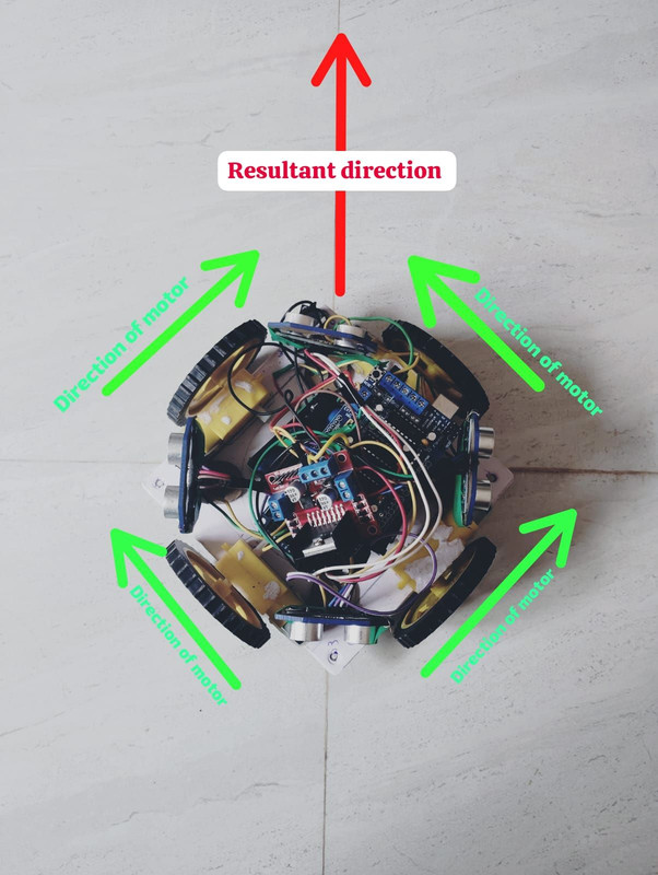
Key Learnings:
- Learned to integrate multiple sensors into a cohesive system.
- Developed skills in managing and troubleshooting complex hardware setups.
- Gained insight into the challenges of multi-protocol communication and how to overcome them.
6)Battery Management System (BMS)
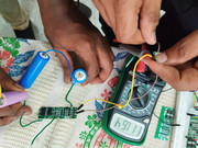
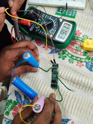
I successfully completed the design and implementation of a Battery Management System (BMS) for an assembly of battery cells configured in a row x column matrix. The BMS technology oversees battery operations, ensuring stable voltage and current delivery over time while managing load variations. The system integrates sensors for real-time monitoring, ensuring optimal performance and safety. The photos below showcase the completed hardware setup and configuration of the BMS:
Task 7: Making a Lithium-ion Battery Pack with 3 18450 Batteries and BMS
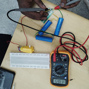
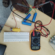
I assembled a lithium-ion battery pack using three 18450 cells connected in series (3S configuration), providing a total voltage of 11.1V. The Battery Management System (BMS) was integrated to ensure safe operation, including protection against overcharge, over-discharge, and short circuits. Nickel strips were used to connect the cells, and the pack was insulated with heat shrink tubing. Finally, the voltage output was verified using a multimeter to confirm proper assembly and functionality.
