BLOG · 14/10/2026
Level 1- Part 2

This Article is yet to be approved by a Coordinator.
Task 15 :- AC to DC Conversion and Observing Direct DC vs. Rectified DC
objective
To Simulate an AC signal using Arduino’s PWM output, then convert it to DC using half-wave rectification. Use a diode to block the negative cycle and a capacitor to filter the signal, producing rectified DC. Compare the LED brightness when powered by a direct DC source (battery) versus rectified DC output.
Key Features and Working
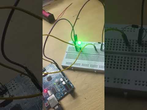
- Uses an Arduino PWM output (filtered or used as a pulsed source) to simulate an AC-like signal, since the Arduino cannot output a true AC waveform.
- A diode (e.g., 1N4007) is connected in series to perform half-wave rectification, conducting only during the positive half-cycle and blocking the negative half-cycle.
- The rectified output is a pulsating DC with gaps, which makes it unsuitable to power a load directly.
- A smoothing capacitor placed across the load charges to the peak voltage and discharges slowly when the input drops, reducing ripple and giving a steadier DC output.
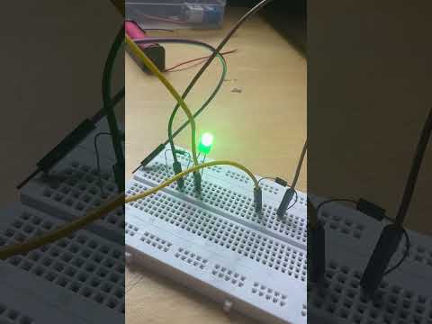
- An LED with a current-limiting resistor is connected as the load to visually show the quality of the output.
- The same LED is then powered from a direct DC source (battery) for comparison.
- The LED glows brighter and more stable on the battery, since the filtered rectified DC has lower average voltage (diode drop of about 0.7 V) and some residual ripple.