

Task 4: Smart active battery balancer using Arduino Uno + IRF830 N-MOSFET + CL100 NPN transistor + Two Li ion unbalanced batterires
Aim:
To design and implement a smart active battery balancer circuit using an Arduino Uno that monitors and equalizes the voltage levels of two unbalanced Li-ion cells, by intelligently controlling current flow with an IRF830 n-MOSFET and CL100 NPN transistor.
Components required:
1.Two unbalanced Li ion batteries
2.Arduino Uno
3.IRF 830 N-MOSFET
4.CL100 NPN Transistor
5.Breadboard
6.Jumpers
7.Current limiting resistors
Theory
What is Battery Balancing?
Battery balancing is the process of equalizing the voltage or state-of-charge (SoC) of individual cells in a multi-cell battery pack. Over time, due to manufacturing differences, self-discharge rates, and unequal loads, cells can drift apart in voltage. This imbalance leads to:
- Reduced usable capacity of the battery pack
- Uneven charging/discharging
- Premature aging of weaker cells
- Safety risks (e.g. overcharging a full cell)
Balancing ensures all cells are at similar voltage levels, which improves the efficiency, lifespan, and safety of the battery pack.
Types of Battery Balancing:
1.Passive Balancing:
- Excess charge from higher-voltage cells is dissipated as heat through resistors.
- Simple, but wastes energy. 2.Active Balancing:
- Actively transfers charge from higher-voltage cells to lower-voltage ones.
- More energy-efficient, suitable for smart battery management systems.
Concept of Smart Active Battery Balancer:
This task focuses on active balancing between two unbalanced Li-ion cells, using a microcontroller (Arduino Uno) and discrete components.
Voltage Monitoring (Arduino Uno):
- The Arduino reads voltage levels of both Li-ion cells using analog input pins (with voltage dividers).
- It continuously compares the two voltages to detect imbalance.
Balancing Action:
- When one battery’s voltage is significantly higher than the other (e.g., >0.1V difference), the Arduino initiates a charge transfer.
This action is controlled using:
- IRF830 n-MOSFET: Acts as a low-side electronic switch for transferring current.
- CL100 NPN Transistor: Can serve as a gate driver for the MOSFET or as part of a current control or direction logic.
How Charge is Transferred:
- When the MOSFET is turned ON by the Arduino, it allows current to flow from the higher-voltage battery to the lower-voltage one, balancing their charge levels over time.
- The process continues until the voltage difference falls below a safe threshold (e.g., <0.05V), at which point the Arduino stops the balancing.
Why This is “Smart”:
- The system automatically senses and corrects imbalance in real-time.
- It is energy-efficient compared to passive balancing.
- It can be enhanced with data logging, display, or wireless communication features.
Procedure:
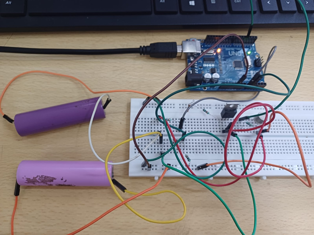
- Circuit Setup
- Connect two unbalanced Li-ion cells (e.g., 3.7V each).
- Use voltage dividers to reduce battery voltages to below 5V for Arduino analog inputs (A0 and A1).
- Connect IRF830 MOSFET:
- Drain to positive terminal of higher voltage battery.
- Source to positive terminal of lower voltage battery.
Use CL100 NPN transistor:
- Collector to MOSFET Gate (through resistor, e.g., 220Ω).
- Emitter to GND.
- Base connected to Arduino digital pin via a resistor (1kΩ).
- Arduino Logic
- Read voltages of both batteries.
- Calculate the difference.
- If the difference exceeds a threshold (e.g., 0.1V):
- Arduino triggers the CL100 transistor to turn on the MOSFET.
- This allows current to flow from high-voltage cell to low-voltage one.
- Stop transfer when voltages are nearly equal (within safe threshold).
- Loop and Monitor
- Continuously monitor voltages and balance as needed.
- Add Serial Monitor output for live tracking.
Relation between input voltage and output voltage
Vout = Vin × (R2 / (R1 + R2))
Expected outcome
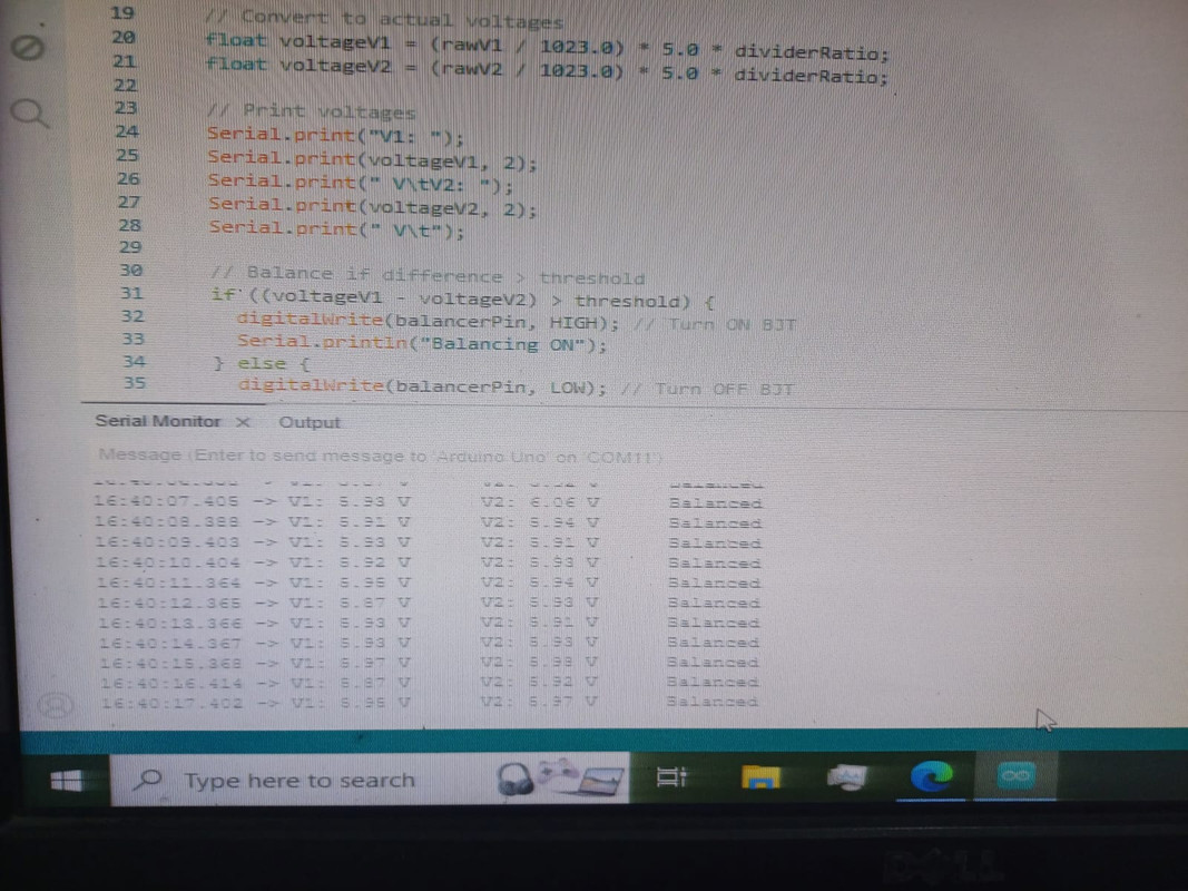
1.Voltage Monitoring:
- Arduino continuously reads the voltages of both Li-ion batteries using analog inputs through voltage dividers.
- Displayed on the Serial Monitor in real-time.
2.Balancing Activation:
- When the voltage difference exceeds a set threshold (e.g., 0.1V):
- Arduino triggers the CL100 NPN transistor.
- The CL100 turns on the IRF830 N-MOSFET.
- Charge flows from the higher voltage battery to the lower one.
3.Automatic Cutoff:
- Balancing continues until the voltage difference falls below the threshold.
- The Arduino then turns off the MOSFET via the CL100, stopping the transfer.
4.Voltage Equalization:
Over time (depending on battery capacity and circuit current capability), both batteries will approach nearly equal voltages (e.g., both ~3.85V).
Reference links:
https://cellsaviors.com/blog/active-passive-balancing?utm_source=chatgpt.com https://320volt.com/en/balancing-li-ion-li-polymer-batteries-battery-balancing-circuit/
Task 5: Demonstration of Regenerative Braking System Using Arduino PWM Control
Aim:
To demonstrate the concept of regenerative braking using a DC motor controlled by Arduino PWM, where the motor acts as a generator during braking, converting kinetic energy into electrical energy.
Components required:
1.9V DC motor
2.Push button
3.LED
4.220 ohm resistors
5.CL100 NPN transistor
6.Breadboard
7.Jumpers
8.Arduino uno
Theory:
In electric vehicles, regenerative braking converts the vehicle’s kinetic energy into electrical energy during deceleration, instead of wasting it as heat. The motor acts as a generator, feeding energy back into the system.
In this task:
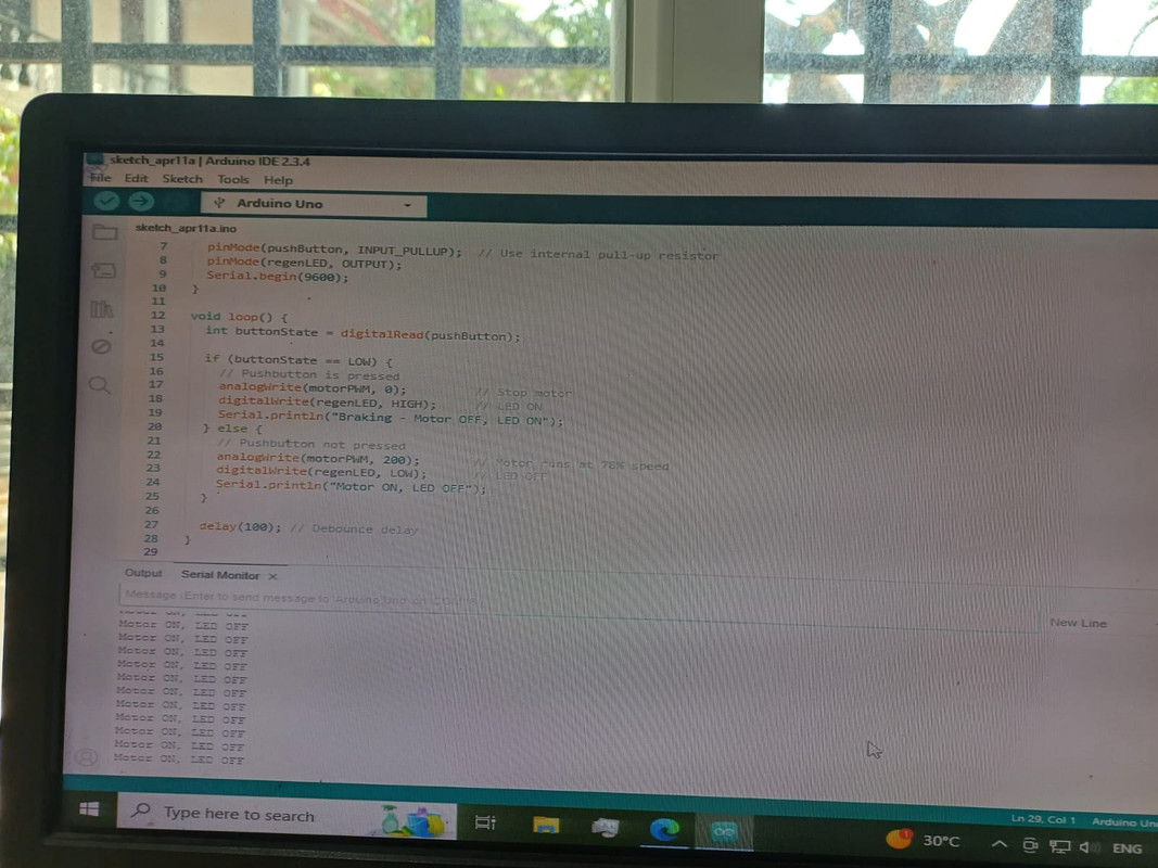
- A 9V DC motor is powered via PWM (Pulse Width Modulation) from an Arduino Uno using a CL100 NPN transistor as a switch.
- When the push button is not pressed, the motor spins and the system simulates normal operation.
- When the push button is pressed, PWM is stopped, and the motor’s terminals are rerouted to an LED + resistor, acting as a load.
- The motor continues to spin due to inertia and acts as a generator, lighting up the LED – demonstrating regenerative braking.
Significance of PWM:
- Speed Control of the DC Motor
- PWM allows you to control the speed of the DC motor efficiently. By adjusting the duty cycle of the PWM signal (the percentage of time the signal is HIGH in one cycle):
- Higher duty cycle (e.g., 80%) → More power to motor → Higher speed
- Lower duty cycle (e.g., 30%) → Less power → Slower speed
- This mimics real-world electric vehicle operation, where motor speed changes based on user throttle input.
- Smooth Transition to Regenerative Braking
- The motor is first accelerated using PWM.
- On pressing the brake button, the Arduino cuts the PWM output to zero, disconnecting motor power.
- The motor then continues to spin due to inertia and acts as a generator, feeding power to the LED load.
Without PWM, you'd have a simple ON/OFF motor control using full voltage. This would not:
- Allow variable speed control
- Demonstrate realistic energy generation based on previous speed
- Mimic real braking behavior, where regeneration depends on how fast the motor was spinning.
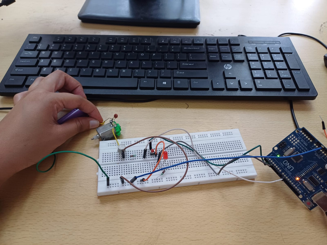
Procedure:
Motor Control Circuit:
1.Connect motor’s positive terminal to +9V power supply.
2.Connect motor’s negative terminal to the Collector of the CL100 transistor.
3.Connect Emitter of the CL100 transistor to GND (common ground with Arduino and power supply).
4.Connect Arduino pin D9 (PWM) to the Base of the CL100 transistor through a 220Ω resistor.
5.Place a 10kΩ resistor (optional) between the transistor's base and ground for better signal stability.
6.Connect a flyback diode (1N4007) across motor terminals: cathode to +9V, anode to collector, to protect the transistor.
Braking Control (LED Load):
1.Connect the LED + 220Ω resistor in parallel to the motor terminals, but control it using Arduino pin D8.
2.Connect the push button between Arduino pin D2 and GND. Enable internal pull-up in code.
Expected outcome:
- When powered, the motor spins at medium speed via PWM control.
- Pressing the pushbutton simulates braking:
- The motor stops receiving power.
- The motor, still spinning due to inertia, generates voltage.
- This voltage lights up the LED, demonstrating energy recovery.
- This clearly shows the principle of regenerative braking using low-cost components.
https://www.youtube.com/watch?v=p2rDnx2JV-k
https://testbook.com/mechanical-engineering/regenerative-braking-system