
BLOG · 14/9/2023
Level 1 tasks (contd)

This Article is yet to be approved by a Coordinator.
BLOG · 14/9/2023
 \n
\n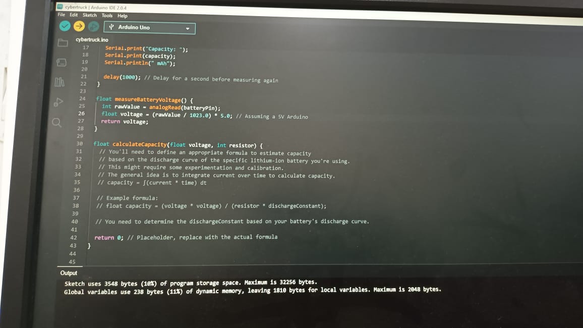 \n- As a result of our experiment, we observed that the lithium-ion battery charged steadily and safely.\n- The Arduino code effectively controlled the charging current, preventing overcharging and ensuring the battery's health and safety.\n\n## Key Learnings\n\n- Battery Charging Principles: We gained a better understanding of lithium-ion battery charging principles and the importance of controlled charging to extend battery life.\n- Arduino Programming: This project enhanced our skills in programming Arduino boards for specific tasks, such as battery management.\n- Safety Protocols: We learned about safety protocols and measures to avoid overcharging and protect the battery from damage.\n\n## Conclusion\n\nThe lithium-ion battery charging project demonstrated the successful development of a battery charging system using an Arduino and breadboard jumpers. By carefully monitoring the battery's voltage and controlling the charging current, we created a safe and efficient charging solution.\n\nIn conclusion, this project not only improved our knowledge of battery charging but also honed our skills in Arduino programming and circuit design. Understanding the principles of lithium-ion battery charging is crucial for developing reliable and safe energy storage systems.\n\n\n---\n# Understanding 555 Timer And LDR\n---\n# Solar Panel\n## Introduction\nThe purpose of this experiment was to create a small solar panel using LED diodes and examine its performance in generating electricity. The experiment involved measuring the voltage output of the solar panel under different lighting conditions.\n\n## Experimental Results\n- Initial Readings:\n - Under natural light or room light, the voltmeter displayed a very small voltage reading, indicating a low power output from the solar panel.\n\n- Impact of Flashlight:\n - When a flashlight was directed towards the solar panel, the voltmeter reading increased significantly. The additional light source enhanced the power output of the solar panel.\n\n
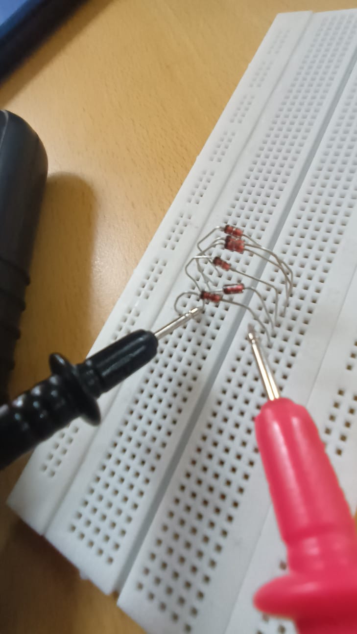 \n
\n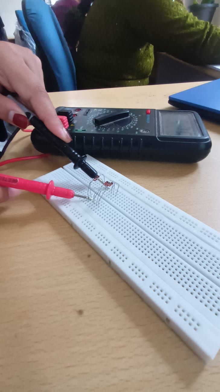 \n\n## Key Learnings\n>- Light Intensity and Power Output: This experiment showcased the significant impact of a flashlight on increasing the voltage output.\n>- Parallel Connection: Practical knowledge of how to effectively combine multiple components to maximize output and efficiency.\n>- Importance of Light Exposure: This experiment emphasized the critical role of proper light exposure in achieving optimal performance from solar panels. It highlighted the need for considering lighting conditions in solar panel installations.\n\n## Conclusion\nThe experiment demonstrated that the small solar panel, consisting of 5 LED diodes, could generate a measurable voltage output. However, the initial readings were quite low under natural or room light conditions. The increase in voltage reading when using a flashlight confirmed the dependence of the solar panel's performance on light intensity.\n\nOverall, this experiment provided valuable insights into the behavior of a small-scale solar panel and deepened my understanding of solar energy generation, component connections, and the influence of light intensity on power output.\n\n\n---\n# Task 13 - Solar Tracker\n\n## Introduction\n\nIn this project, a solar tracker system had to be designed and implemented using Arduino. The solar tracker is equipped with an LCR sensor, a breadboard, jumper wires, and a resistor. The primary goal of this project is to efficiently orient a solar panel to maximize its exposure to sunlight throughout the day, thus enhancing its energy generation capabilities. \n\n## Experimental Results\n\n### Setup\n\n- Components Used:\n - LCR Sensor\n - Breadboard\n - Jumper Wires\n - Resistor\n - Arduino Board\n\n- Code Implementation:\n - We developed and uploaded a custom Arduino code to control the solar tracker.\n - The code reads data from the LCR sensor to determine the optimal orientation of the solar panel.\n\n
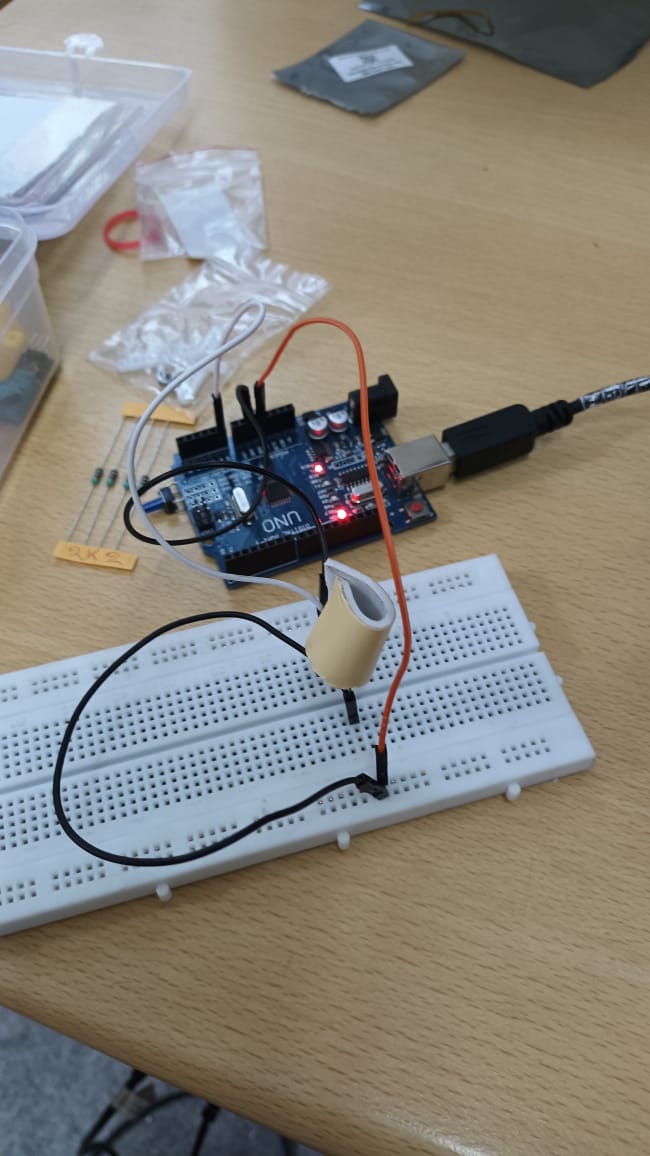 \n
\n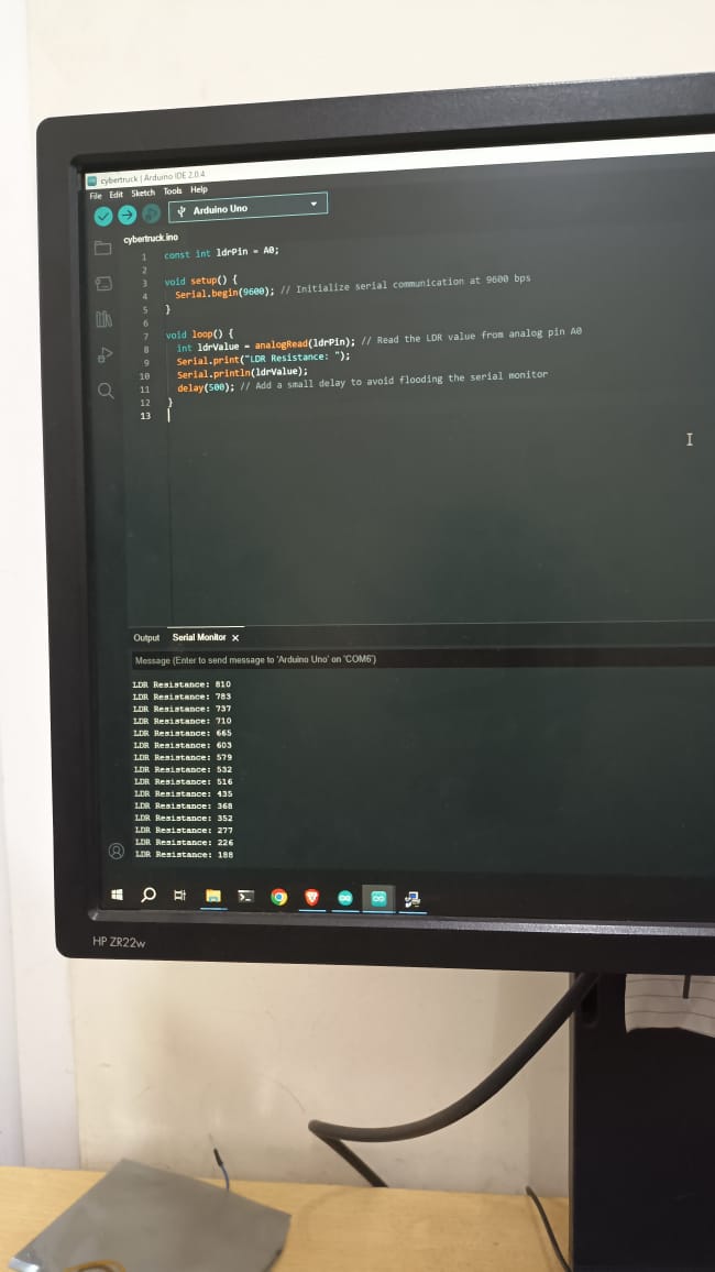 \n\n### Analysis\n\n- We analyzed the collected data to evaluate the effectiveness of the solar tracker in optimizing solar panel orientation.\n- The analysis included tracking the movement of the solar panel throughout the day and comparing it with static solar panels.\n\n## Key Learnings\n\n- Solar Panel Efficiency: We learned about the importance of aligning solar panels with the sun to maximize energy production.\n- Sensor Calibration: We gained experience in calibrating and utilizing sensors like the LCR sensor for precise measurements.\n- Arduino Programming: This project enhanced our skills in programming Arduino boards for automation tasks.\n- Data Analysis: We developed data analysis skills to evaluate the effectiveness of our solar tracker.\n\n## Conclusion\n\nThe solar tracker project has provided valuable insights into solar panel optimization techniques. By using an LCR sensor and an Arduino board, we successfully developed a solar tracker system that dynamically adjusts the solar panel's orientation throughout the day. This system has the potential to significantly increase the energy output of solar panels, making them more efficient and sustainable sources of power.\n\nIn conclusion, this project has not only enhanced our understanding of renewable energy systems but also improved our technical skills in sensor integration, data analysis, and Arduino programming. The successful implementation of the solar tracker reaffirms the importance of innovation in the field of sustainable energy.\n\n