
BLOG · 28/3/2026
EV-RE level-001 part-2
 | OP |
TASK 9: Thinkercad
Objective - Create a thinkecad accout, get familiar with the application, understand the example circuits given and stimulate a simple circuit using an ultrasonic sensor to estimate the distance between an obstacle and the sensor. Display the results on the serial monitor. Create a radar system utilising an ultrasonic sensor and servo motor to detect objects within a certain range. The ultrasonic sensor emmits sound waves and measures the time taken for them to bounce back, while the sevo motor rotates the sensor to cover a wider area, providing a simple yet effective detection mechanism.
Learnings and outcomes -

An ultrasonic radar system uses ultrasonic waves to measure the distance of an object and visualizing the position often by implementing sensors and rotating mechanism.
For this task, I have created my account in thinkercad and first made a LED blink circuit. This made me familiar with the application. Then I made a ultrasonic radar system which measures both distance and angle the object is located.
TASK 10 : Speed Control Of DC Motor
Objective - Explore basic techniques for controlling DC motors, understand the command DC motors using the L298N motor driver and the Arduino board. Using an UNO and H-Bridge L298N motor driver, control the speed of a 5V BO motor, try simulating this on thinkercad and then perform it on hardware, record videos of you doing the same.
Ouctcomes and Learning-

Speed control of DC motor using L298N motor driver and Arduino -
The L298N motor driver serves as the critical bridge between low- powered Arduino and high-current DC motors. It acts quite similar as power amplifier for our control signals. The Arduino generates 5V logic signals at milliamp levels, but DC motors often require more than 5V at several amps. The L298N handles this translation safely.
In simple words, when potentiometer sends analog signals to Arduino which converts it into a PWM signal and send it to the motor driver.
PWM(Pulse Width Modulation) - It is a method that changes the pulse signal's width in electrical systems to regulate the average power supplied to a load.
Components required -
- Arduino Uno
- Gear DC motor
- Potentiometer
- L298N motor driver
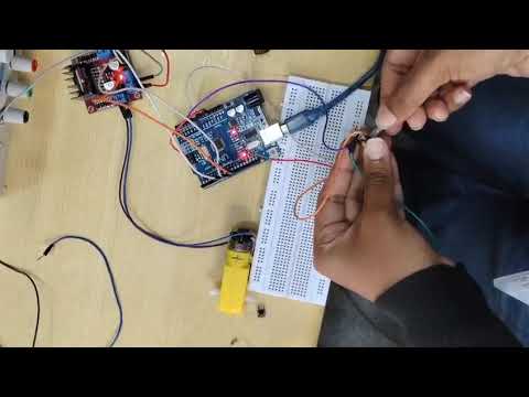
Connections are made as showed in the circuit diagram -

TASK 11 : LED Toggle Using ESP32
Objective - Learn the working of ESP32 and create a standalone web server with ESP32 that controls the LED connected with ESP32 GPIOs. Use the Arduino IDE to code and upload the program to ESP32. Learn to configure the IDE to upload code to ESP32.
Approach -
Components required -
Component Quantity Value LED 2 -- ESP32 1 -- Resistors 2 220Ω
Circuit diagram -


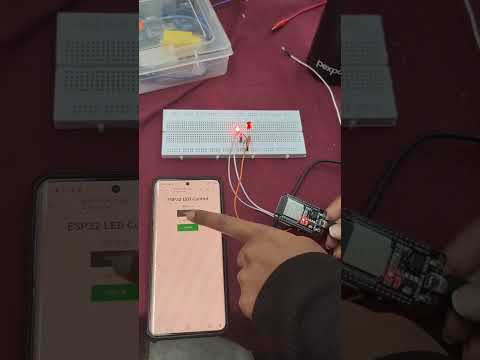
After uploading the required code to ESP32, copy the IP address which is displayed in the serial monitor and search it in the search engine using the same Wi-Fi-network that was entered in the code.
Below you will see the outcome of this task -
Outcome-
TASK 12 : Soldering Perquisites
Objective - Learn about the soldering equipment in our lab, the solder, the soldering iron, soldering wick, flux, etc. Learn to use them and perform basic soldering on the perf board, for example a LED circuit in the presence of a coordinator and document the same.
Learning and outcomes -

- Soldering is the process of melting a metal alloy to join two or more electronic components together.
- Tools required are soldering iron, soldering flux, a solder, sand paper(or wet sponge) and a soldering station for temperature control.
Note :- Suitable temperature for soldering :- Lead-based solder - 180*C - 190*C
- Lead-free solder - 217*C - 227*C
TASK 13 :
Objective - Design a 555 astable multivibrator with duty cycle 60%, rig up the circuit on the bread board and by using the probes observe the output of your circuit in the DSO.
Outcomes and Learning -

In Astable mode, 555-timer IC acts as an oscillator that generates square wave.
Components required -
- Capacitors 0.1 µF
- Resistor1 (R1) 2.2kΩ
- Resistor2 (R2) 4.4kΩ (2.2kΩ + 2.2kΩ)
- 555-timer IC
Working -

- In astable mode, the output cycle on and off continuously.
- At the beginning of an on/off cycle, the voltage is low at C1, trigger pin and the threshold pin.
- Whenever the trigger pin voltage is low, the output is on and the discharge pin is off. Since the discharge pin is off, current can flow through R1 and R2, charging the capacitor C1.
- Once C1 charges to 2/3 Vcc, the output is switched off by the threshold pin. When the output goes off, the discharge pin switches on. This allows the charge accumulated on capacitor C1 to drain to ground.
- Once the voltage crosses C1 drops to 1/3 Vcc, the trigger pin turns off the discharge pin, so C1 can charge again.


The duty-cycle I obtained is 60.3%
TASK 14 : Karnaugh Maps and Deriving the logic circuit
Objective - For 4 cases, based on door lock/open and key pressed/not pressed. Determine the Karnaugh map and make a burglar alarm using simple logic circuits. The buzzer or led blinks when certain conditions are met, you can use push buttons for the door and key.
Outcomes and learning -
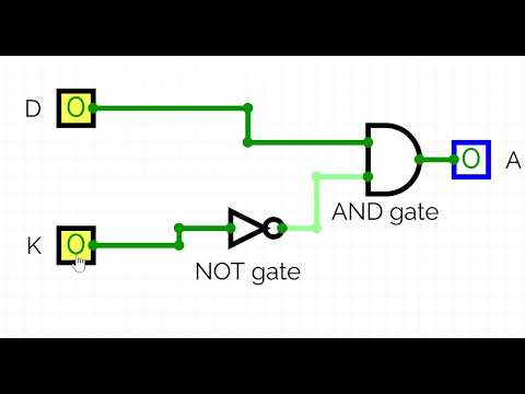
Inputs - D(door) and K(key)
The alarm rings only when the door is open and when the key is not pressed.
Karnaugh map -
| D | K | A |
|---|---|---|
| 0 | 0 | 0 |
| 0 | 1 | 0 |
| 1 | 0 | 1 |
| 1 | 1 | 0 |
Below is the working of logic gate -
TASK 15 : Active Participation
Description - Take part in any technical event, inter or intra college and submit the issued certificate of participation.


I participated in project presentation in KAGADA and I have won in "ctrl+z" competition in IMPETUS.
TASK 16 : Datasheets report writing
Objective - Study the datasheets of any one of the above and write a report on it. Specify about the ICs used in L293D, PWM, H-bridge etc. In case of MQ 135, spectifiy the calibration for different gases and the Freundlich Absorption Theorem Graph.
Outcome -
The L293D is a well-known motor driver integrated circuit (IC) that controls the direction and speed of DC motors and stepper motors. It's commonly used in robotics and embedded systems because it simplifies the connection between motors and microcontrollers.
- IC Overview -
- Type: Quadruple Half-H Driver IC
- Manufacturer: Texas Instruments (originally) and other semiconductor companies
- Functionality: Combines two full H-bridges to enable bidirectional control of two DC motors.
- Package: 16-pin Dual In-Line Package (DIP)
- H-Bridge Concept An H-bridge is a circuit with four switches (transistors) that allows current to flow in either direction through a motor.
- When switches S1 and S4 are ON, current flows one way, so the motor rotates forward.
- When switches S2 and S3 are ON, current flows the opposite way, causing the motor to rotate backward.
- The L293D has these switches built in, allowing easy control of motor direction using logic signals.
- PWM (Pulse Width Modulation) Control
- PWM signals connect to the Enable pins (EN1, EN2) of the L293D.
- By changing the duty cycle of the PWM signal, the average voltage supplied to the motor changes.
- This method allows speed control without changing the supply voltage.
- Example:
- 50% duty cycle means the motor runs at half speed.
- 100% duty cycle means the motor runs at full speed.
- Pin Configuration

- Pins 1 & 9 (Enable 1, Enable 2): Enable or disable motor channels.
- Pins 2, 7, 10, 15 (Input pins): Logic inputs from the microcontroller.
- Pins 3, 6, 11, 14 (Output pins): Connect to motor terminals.
- Pins 4, 5, 12, 13 (Ground): Common ground.
- Pin 8 (Vcc2): Motor supply voltage (up to 36V).
- Pin 16 (Vcc1): Logic supply voltage (5V).
Electrical Characteristics
- Logic Voltage (Vcc1): 4.5V to 5.5V
- Motor Voltage (Vcc2): 4.5V to 36V
- Output Current per Channel: 600 mA (up to 1.2A peak)
- Power Dissipation: ~1W at 25°C
- Thermal Shutdown: Built-in protection against overheating.
- Applications
- Robotics (wheel control, robotic arms)
- CNC machines and 3D printers
- Automated toys and hobby projects
- Driving stepper motors in embedded systems
Reference :- Texas instruments
TASK 17 : Introduction to VR
Objective - Familiarise yourself with what Virtual Reality is. Make a detailed study about what's the difference between AR and VR. Mention about trends in the space and technology stack being developed. Make about Indian companies in this space, Make the report with detail.
Learning - Click here to view my full report