
BLOG · 18/8/2024
LEVEL 3 Report

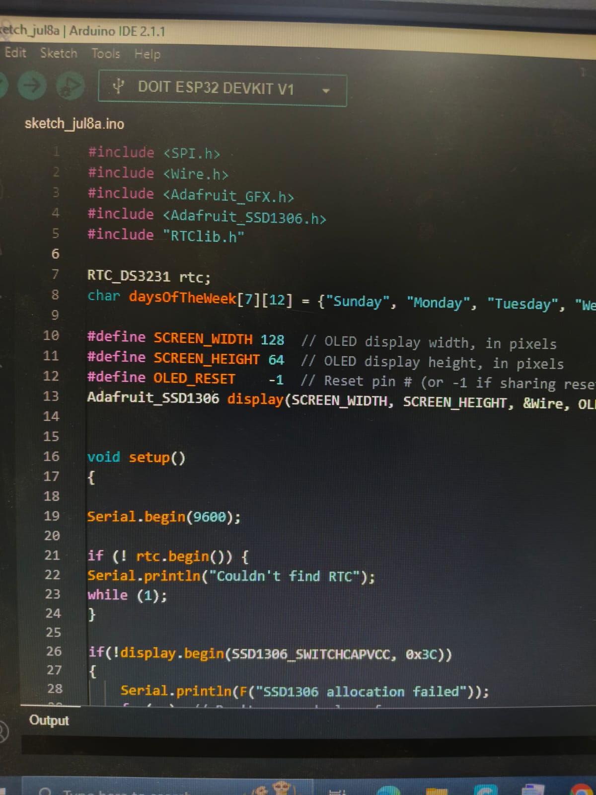
Task 3 - Interfacing RTC time module with ESP32
Objective:
Our main task was to display Real time data on a OLED using DS3231 (RTC) module along with ESP32.
The list of Components that I used To perform this task include:
ESP32
RTC DS3231 module
Oled
jumper wires
Breadboard
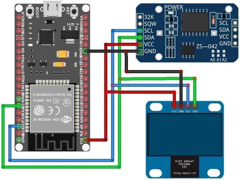
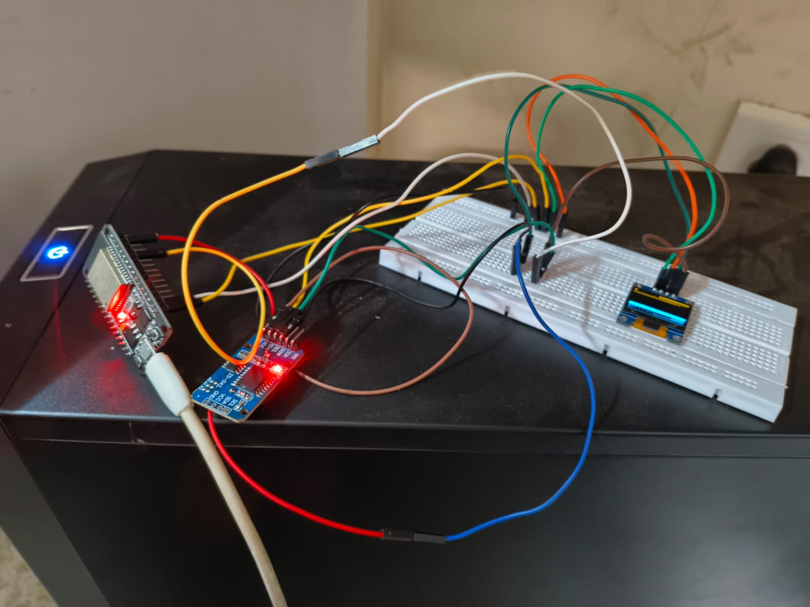
1.The DS3231 & the OLED Display both are I2C Module. So we just need 2 pins for connection. So, I have connected the Serial Data (SDA) pins to ESP32 GPIO21 pin & Serial Clock (SCL) to ESP32 GPIO22 pin. Supply 3.3V to OLED & RTC Module through 3.3V pin of ESP32.
2.A precision temperature-compensated voltage reference and comparator circuit monitor the status of VCC to detect power failures, to provide a reset output, and to automatically switch to the backup supply when necessary.
Task 8 - Alexa Light Control
Objective:
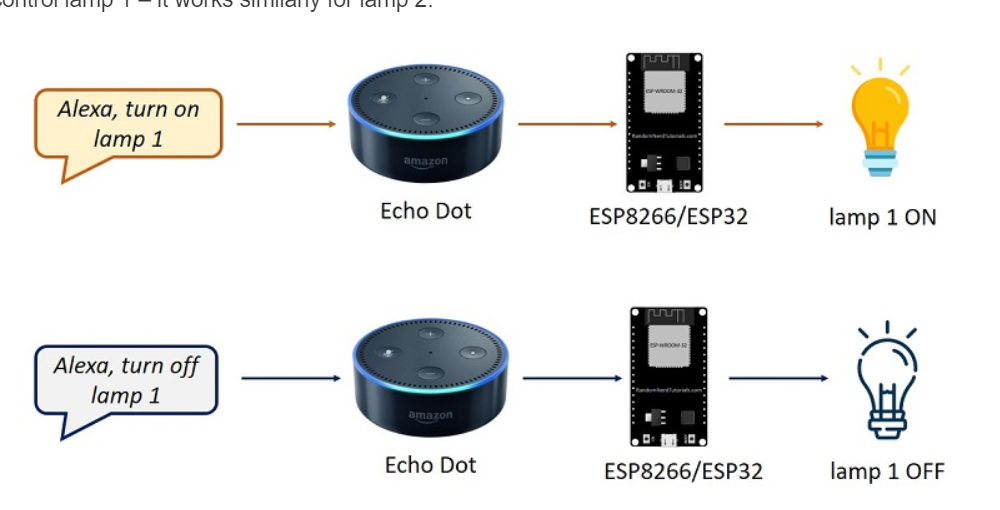
Our main task was to turn on leds by sending instructions/commands to alexa or any other communication protocol
Below figure shows The process of Controlling Lights through Alexa and ESP32 :
 .
.
I have used Blynk as a communication protocol
Steps to Control LED Using Blynk with ESP32:
1.Firstly , I Created a New Project in Blynk: The procedure goes like this ,Open the Blynk app, create a new project, and select ESP32 as the device. we will receive a Token via email. This token is needed to communicate with the Blynk server.
-
Set up Widgets in Blynk: Add a Button widget to the dashboard. Configure the button for turning the LED on and off.
-
Install the Blynk Library: In Arduino IDE, go to Sketch > Include Library > Manage Libraries and search for "Blynk."
Install the Blynk library.
Upload the code shown below and when commands are passed through buttons , toggling of leds can be witnessed !!

Task 2 - Introduction to RFID
Objective:
The main objective we had was to read a RFID (radio frequency Identification).
The components That I used to perform the above mentioned task include :
ESP32: Since arduino are not featured with bluetooth, wi-fi etc , Esp32 is used .
RFID (Radio Fequency Identification)
Leds (to display the visual output)
Breadboard .
WORKING
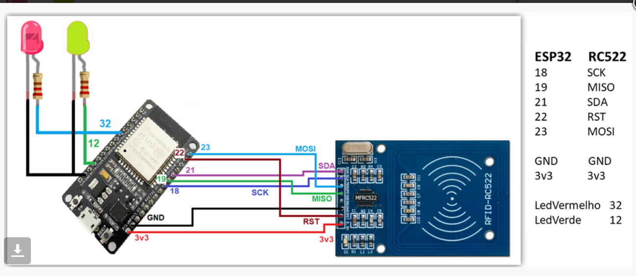
1.RFID Reader Module: Connected to the ESP32 via SPI or I2C for communication.
2.Power and Initialization: ESP32 powers the RFID reader and initializes communication.
3.Card Detection: The RFID reader generates an electromagnetic field, and the card transmits its UID when in range.
4.UID Transmission: RFID reader captures the card's UID and sends it to the ESP32.
5.Data Processing: ESP32 processes the UID, possibly comparing it with a list of authorized UIDs.
6.Action Trigger: Based on the UID, the ESP32 triggers an action (e.g., unlocking a door, turning on a device).
7.Continuous Monitoring: ESP32 loops back to monitor for more RFID cards.

Task 6 - Controlling multiple peripherals using SPI Protocol
1.SPI stands for Serial Peripheral Interface, and it is a synchronous serial data protocol used by microcontrollers to communicate with one or more peripherals. For example, your ESP32 board communicating with a sensor that supports SPI or with another microcontroller.
2.In an SPI communication, there is always a controller (also called master) that controls the peripheral devices (also called slaves). Data can be sent and received simultaneously. This means that the master can send data to a slave, and a slave can send data to the master at the same time.
3.For SPI communication you need four lines:
MISO: Master In Slave Out MOSI: Master Out Slave In SCK: Serial Clock CS /SS: Chip Select (used to select the device when multiple peripherals are used on the same SPI bus).
Most wonderful Advantage : One of the most significant advantages of SPI (Serial Peripheral Interface) is its high-speed data transfer capability.


Task 7 - Telegram Bot Motor control
Task was to Create a Telegram bot to turn on a motor in both the directions Using ESP32 as the interface for this task.
1.Through this task , Firstly I have learnt to build a telegrom Bot .
2.The same telegram bot which I created is used to control the specified task which is controlling a motor in this case
The procedure is very simple :
1.Create Telegram Bot:
2.Use Botfather to create a bot and get the token. Set Up ESP32 Wi-Fi:
3.Program ESP32 to connect to Wi-Fi using the bot’s token. Connect LED to ESP32:
4.Attach the LED to a GPIO pin of the ESP32. Write Code to Control LED:
5.Use Telegram commands like /led_on and /led_off to control the LED state.

Task 1 - Watering a Plant
The main task was to design a system , Using Solenoid Valve to water the plant when the soil moisture content in the soil goes below a certain threshold value and also to use relay to turn off the same .
Components Required
Arduino UNO
Solenoid Valve
IRF540 MOSFET
Pushbutton – 2 nos.
Resistor (10k, 100k)
Diode – 1N4007
Breadboard
Connecting Wires
Working :
1.When button 1 is pressed, Arduino send a HIGH logic to gate terminal of the MOSFET IRF540, connected on the 9th pin of the Arduino.
2.The main function of MOSFET:
As IRF540 is an N-Channel MOSFET, so when its gate terminal gets HIGH, it allow the flow of current from drain to source and turn the solenoid on.
Similarly, when we press the button 2, Arduino sends a LOW logic to the gate terminal of the MOSFET IRF540 which makes the solenoid turn off.

