
BLOG · 16/3/2026
level 0
task 12 to 19
 | OP |
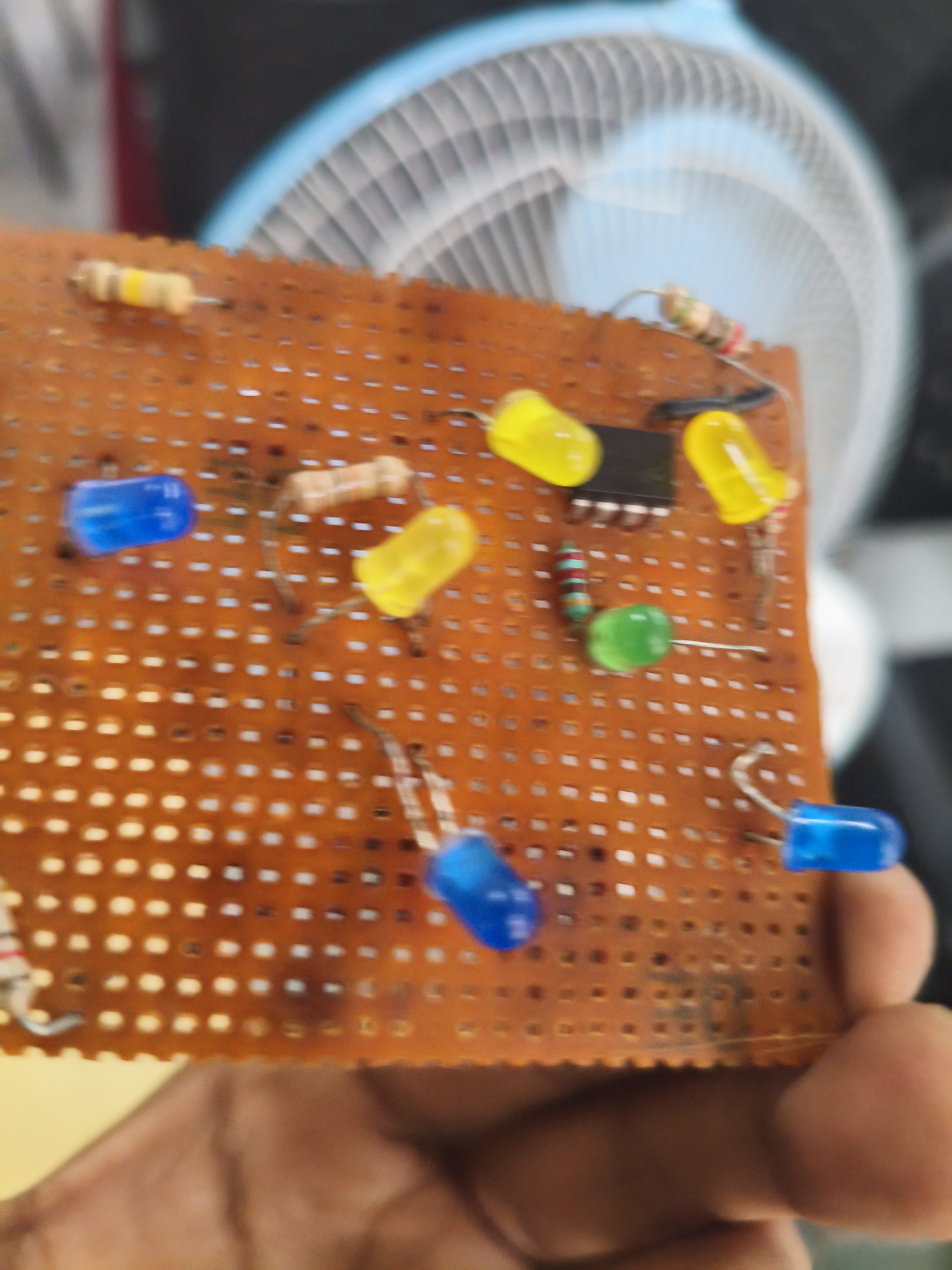
TASK 12: 555 IC astable multivibrator with 60% duty cycle
objective
to design and achieve astable state in the 555 IC with a duty cyclce of 60%
components
| Name | Component | Quantity |
|---|---|---|
| U1 | 555 IC Timer | 1 |
| C1 | 0.01 µF Capacitor | 1 |
| C2 | 0.01 µF Capacitor | 1 |
| R1 | 330 Ω Resistor | 1 |
| R2 | 660 Ω Resistor (330+330) | 1 |
| V1 | VRPS – 5-6V Supply | 1 |
The connnections are made as shown in the below image as given which is refered from the marvel resources
and after all it i gave the power suplly and and auto scaled in the oscilloscope so i got see the duty cycle of 60%
the variation in the waves heavily depends on the capacitor
Duty cycle Expected-60%.My task outcome-57.18%
From calculations R1:R2=1:2
 youtube link yt 555
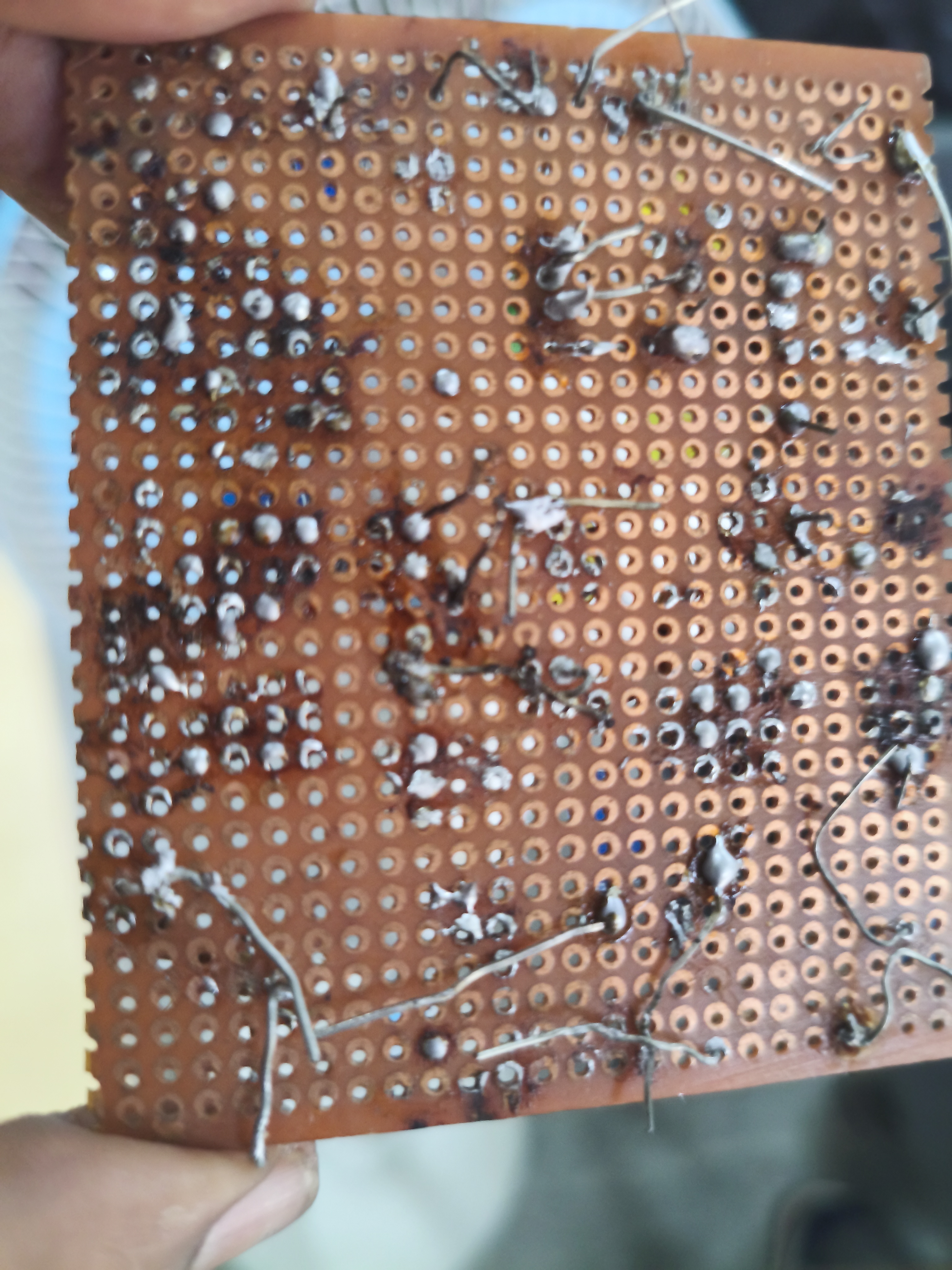
TASK 13: Soldering Prerequisites
objective
To learn and get the insights about the soldering and its meachanism and its uses
i lerant that compnents of the soldering like soldering iron,its tip,flux and the solder
these are used in the soldering process and then when we trun it on it starts heated and raech a optimum temperature then we melt the solder with the help of the tip and apply it on the desired area and the fulx helps to stick it perfertly
then with all this knowledge
i soldered the led in the pup board by my self
TASK 14: Karnaugh Maps and Deriving the logic circuit
objective
to leran about the k maps and design a burgalr alaram circuit based on it
we should make the alaram to ring when there is a abnormal openning of the door
like if the door gets open withouth the key is not normal
but if door is open and key is used is a normal case and alaram should not ring
so let us take some k maops logic as
door open is 1 and closed is 0
and
key used is 1 and not used is 0
 the logical circuit in the simulation
yt k map
the logical circuit in the simulation
yt k map
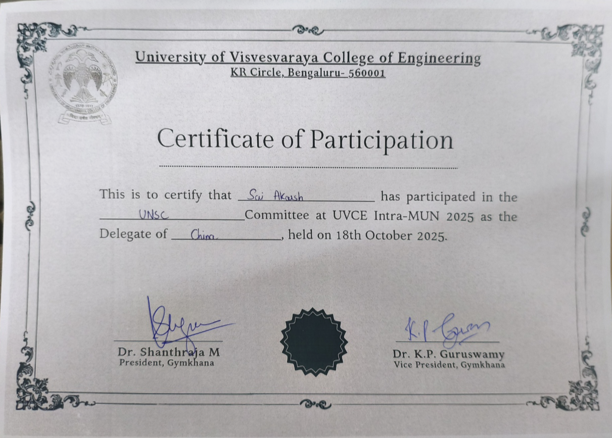
TASK 15: Active Participation
In the part this task i took part in the several events and got th many certitificate one of them was intra mun which was about diplomacy and also we had assces to the internet it was more of a prompting in ai for the best facts and speech and i also had taken amny udemy couresewhich improved my technical skills

TASK 16: Datasheet Study – L293D Motor Driver
Name: Sai Akarsh
Domain: IoT – MARVEL Club, UVCE
Task: Datasheet Study Report
Objective
The objective of this task was to study the L293D motor driver datasheet and understand how it is used to control DC motors using a microcontroller. During this study, I learned about the internal IC structure, H-Bridge concept, PWM speed control, and basic working of the motor driver circuit.
About L293D Motor Driver
The L293D is a motor driver IC used to control motors using a controller like Arduino or ESP32. Motors need more current than what a microcontroller pin can provide. Because of this, the L293D acts as an intermediate driver between the controller and the motor.
This IC has two internal driver channels, which means it can control two DC motors independently. Because of this feature, it is widely used in robotics projects such as two-wheel robots and small automation systems.
H-Bridge Concept (Motor Direction Control)
The L293D uses an internal H-Bridge circuit to control the direction of the motor.
An H-Bridge consists of switching elements arranged in a pattern that looks like the letter H. The motor is placed in the center of this structure. By activating specific switches, the polarity of voltage across the motor changes.
Because of this:
- Current in one direction → Motor rotates forward
- Current in opposite direction → Motor rotates reverse
This method allows a microcontroller to easily control the direction of rotation of the motor.
PWM (Pulse Width Modulation) – Motor Speed Control
The speed of a DC motor can be controlled by adjusting the voltage supplied to it. Instead of changing the voltage directly, a technique called PWM (Pulse Width Modulation) is used.
In PWM, the controller sends very fast ON and OFF pulses to the motor driver. The percentage of time the signal stays ON is called the duty cycle.
- Small duty cycle → Low speed
- Medium duty cycle → Moderate speed
- High duty cycle → Maximum speed
In L293D circuits, the Enable pin is usually connected to a PWM pin of the microcontroller, which allows easy speed control.
Working Principle
The microcontroller sends control signals to the input pins of the L293D. These signals activate the internal H-Bridge circuit. The H-Bridge then allows current to flow through the motor in a specific direction.
Depending on the input signals and PWM applied, the motor can:
- Rotate forward
- Rotate backward
- Change speed
- Stop
This makes the L293D a very useful IC for controlling motors in embedded and robotics projects.
Conclusion
From studying the L293D datasheet, I understood how a motor driver IC helps a microcontroller safely control motors. I also learned the importance of H-Bridge circuits for direction control and PWM for speed control.
The L293D is widely used in robotics and IoT projects because it is simple to use and can drive multiple motors using a single IC.
Images
L293D Motor Driver IC
Task 17: Introduction to VR
so in this task i first played avr gaming i felt it was whole new expiriance although i known i was on the ground it was a differnt expernice
and i so leanrt about AR and VR
and also the difference between the AR and the VR
Task 19: Make a Web app
i made full working web app with the help of the mongo db atals so i took the data base from and then normal i used the node.js fundtion and installed all the library and then pasted the code in it and then complied it and then i used my system to host the web site with help of the local cmd portal all in my computer only
finally i created a simple and fully functional todo app for my slef and got a very good undersanding about all of the things
web working