BLOG · 15/7/2024
Level 1
Coursework of Tasks completed

Task 1:
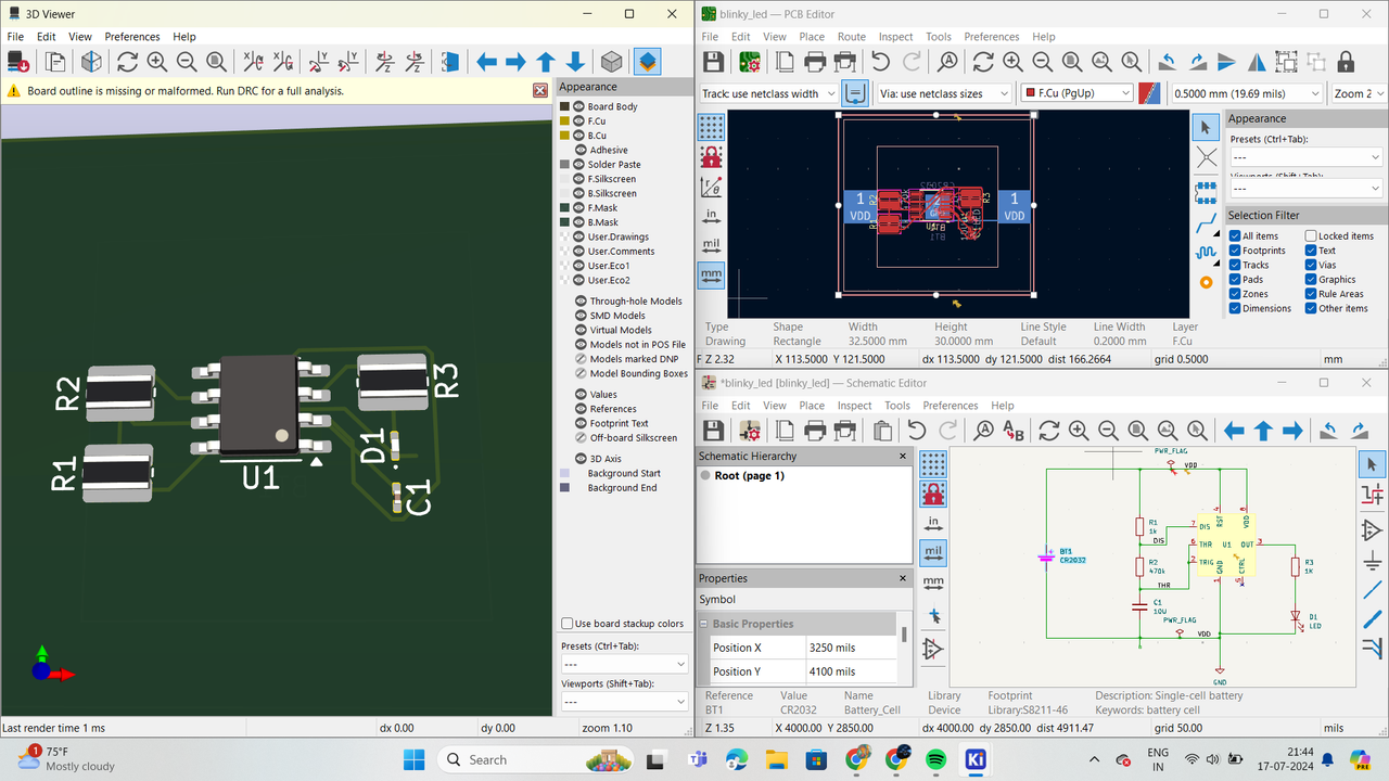
LTspice and Kicad :
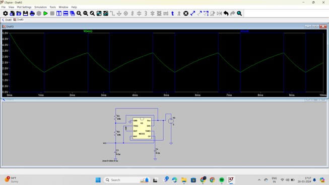
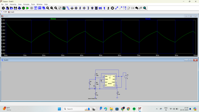
Astable Multivibrator using 555 Timer | Circuit, Duty Cycle, Applications - An astable multivibrator using a 555 timer is a commonly used electronic circuit that generates a continuous square wave output without requiring any external triggering. This configuration is often referred to as a free-running oscillator. With duty cycle of D = (R1+2R2)/(R1+R2).
This allows control over the proportion of time the output remains high compared to the time it stays low. I connected forward bias and reverse biased diode to get 50 % duty cycle .
Task 2 :
Speed control of dc motor :
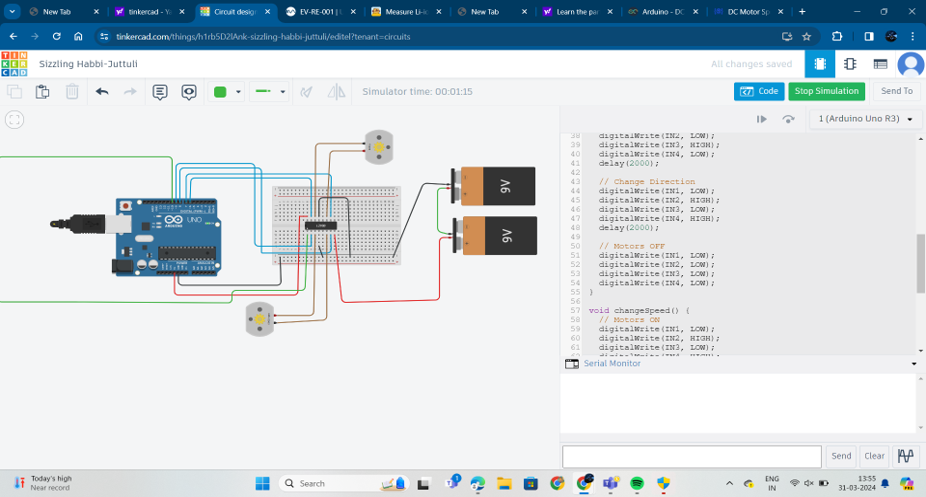
The dual H-Bridge L293D motor driver is a versatile IC designed for this purpose, allowing bidirectional control and speed regulation of DC motors.
L293D Motor Driver The L293D is an integrated circuit that contains two H-Bridge configurations, enabling it to control two DC motors independently. Each H-Bridge consists of four switches (transistors or MOSFETs) that can direct the current through the motor in both directions, providing forward and reverse control.
Speed Control Mechanism
Speed control of the DC motor is typically achieved using Pulse Width Modulation (PWM). PWM involves sending a series of high and low pulses to the motor driver, where the width (duration) of the high pulse determines the average power delivered to the motor. By adjusting the duty cycle of the PWM signal, the speed of the motor shaft can be controlled.

Task 3
Direction control of a Motor :
To control the direction of a DC motor using the L293D motor driver, you need to manipulate the input pins (IN1, IN2, IN3, IN4) of the L293D to change the current flow through the motor, thus reversing its direction. Direction Control Logic
Motor A (connected to IN1 and IN2):
Forward Direction: Set IN1 to HIGH and IN2 to LOW. Reverse Direction: Set IN1 to LOW and IN2 to HIGH.
Motor B (connected to IN3 and IN4):
Forward Direction: Set IN3 to HIGH and IN4 to LOW.
Reverse Direction: Set IN3 to LOW and IN4 to HIGH.
Task 4
Temperature Detection :
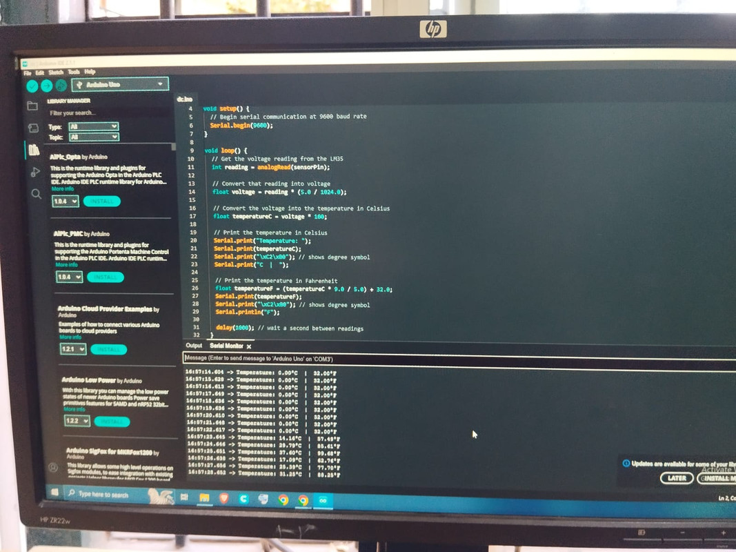
The LM35 is a low voltage, precision centigrade temperature sensor manufactured by Texas Instruments. It is a chip that provides a voltage output that is linearly proportional to the temperature in °C and is, therefore, very easy to use with an Arduino.
Task 5
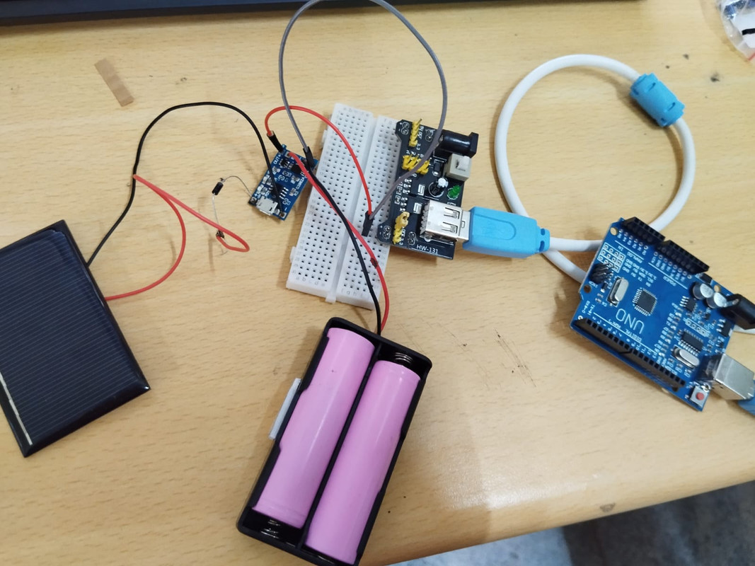
Solar Panel
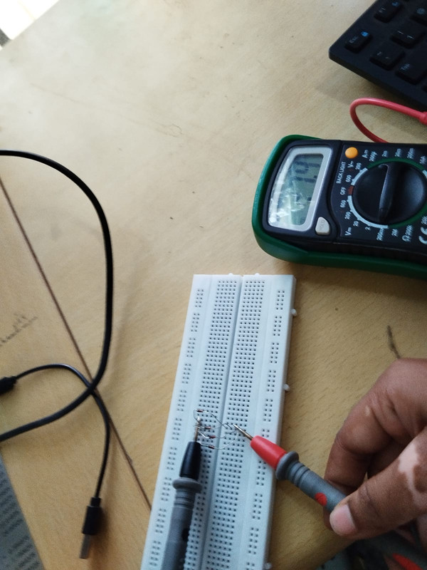
A silicon diode is a two-lead semiconductor that gates current flow in one direction.
solar panel using 1N4148 (run-of-the-mill) diodes
Task 6
Battery charging
Task 7
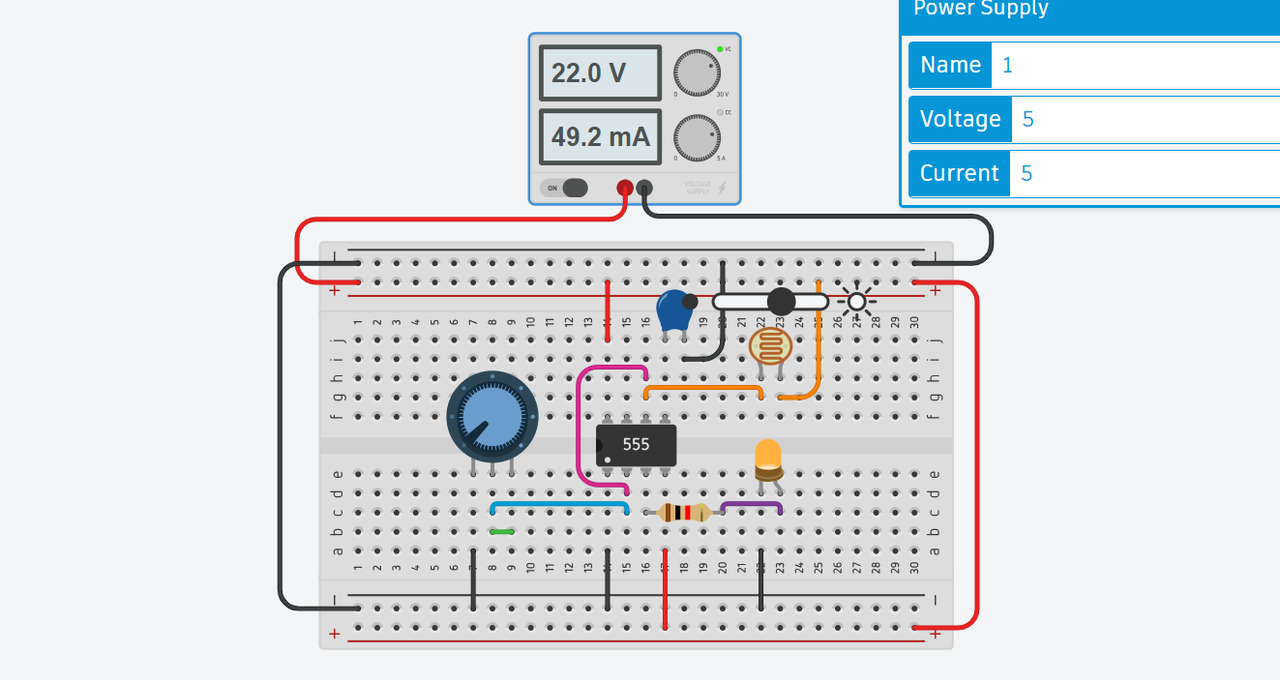
Understanding 555 timer and LDR :
An LDR (Light Dependent Resistor) varies its resistance based on the light intensity it receives. In darkness, its resistance is about 1 megaohm, while in full brightness, it drops to around 5k ohms.
A 555 timer IC is used as a comparator in this circuit, with pin 6 connected to the positive terminal. The output of the 555 timer goes high when the trigger pin (pin 2) is below one-third of the supply voltage and goes low when the trigger pin is above one-third of the supply voltage. The LDR is used to adjust the circuit voltage for light detection.
This circuit is cost-effective and easy to build. On a larger scale, it can be integrated with a solar cell as an energy source and a large light source for automatic nighttime operation, replacing manual control.
Task 8
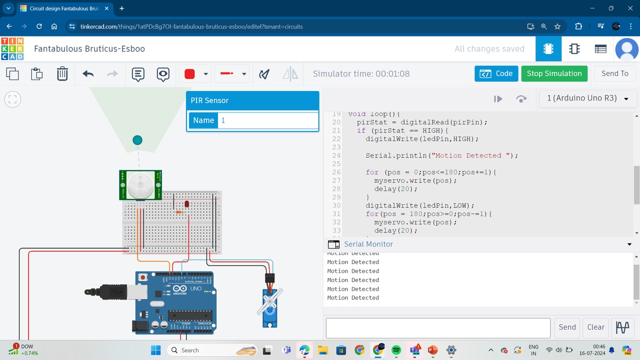
AUTOMATIC DOOR OPENER SYSTEM:
worked on an automatic door opener system using a PIR sensor and Arduino, replacing the CD tray mechanism with a servo motor for controlling the door.PIR Sensor: Detects motion to trigger the door opening mechanism.Servo Motor: Replaces the CD tray mechanism, providing precise control for opening and closing the door. Through this project, I gained valuable knowledge and insights into interfacing sensors with microcontrollers, programming servo motors for smooth operation, and creating efficient automation systems. This experience enhanced my understanding of sensor-based automation and practical implementation of electronic components.
