
BLOG · 22/3/2026
Aadesh's D-P-001 Report (part-2)

TASK 10: Speed Control of DC Motor
Objective:Understand the control DC motors using the L298N motor driver and the Arduino board. Using an UNO and H-Bridge L298N motor driver, control the speed of a 5V motor. Methodology:
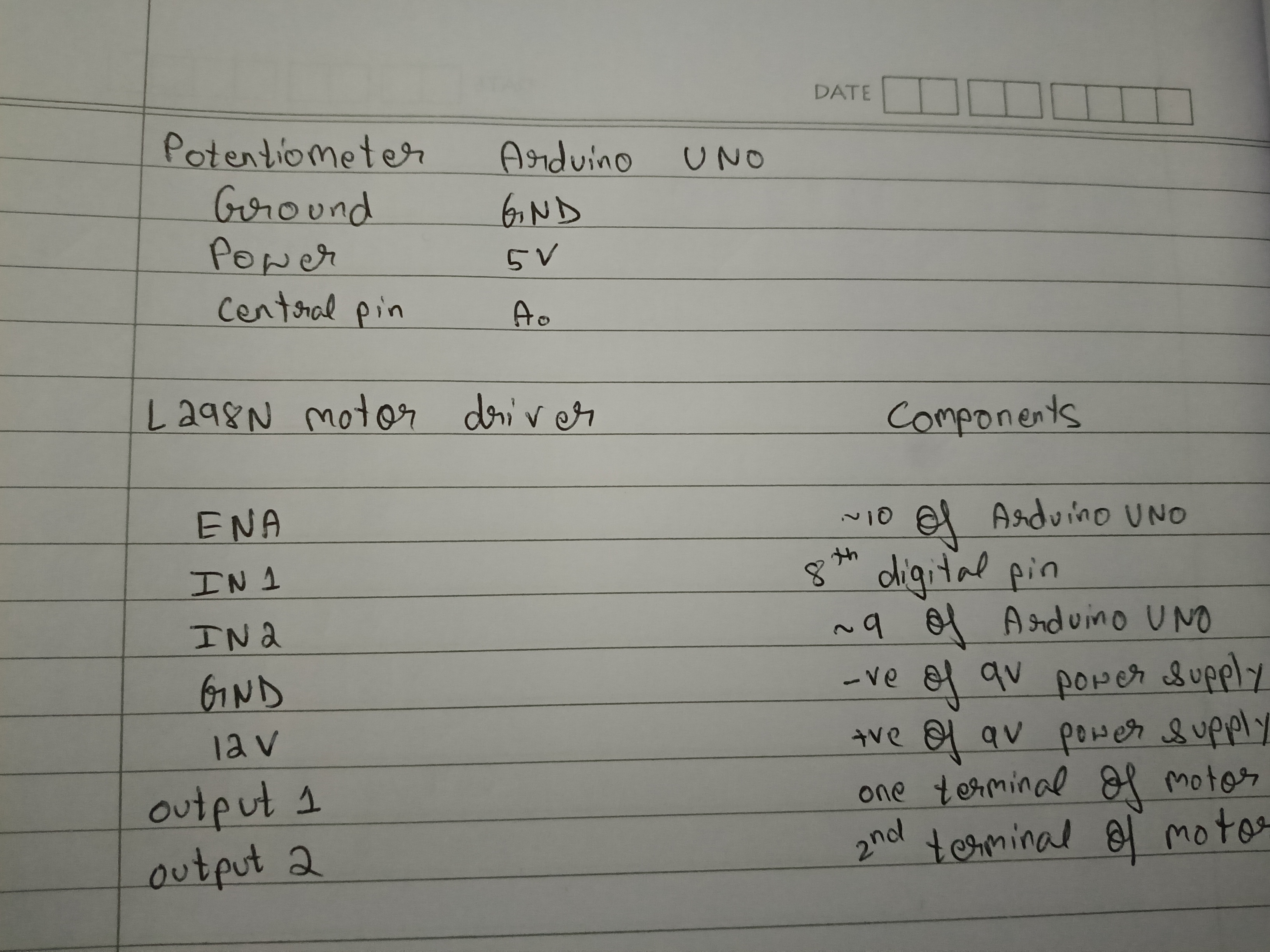
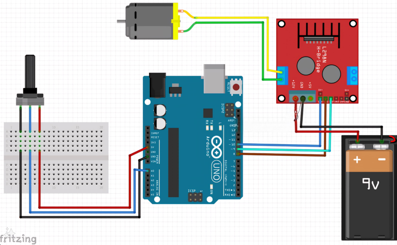
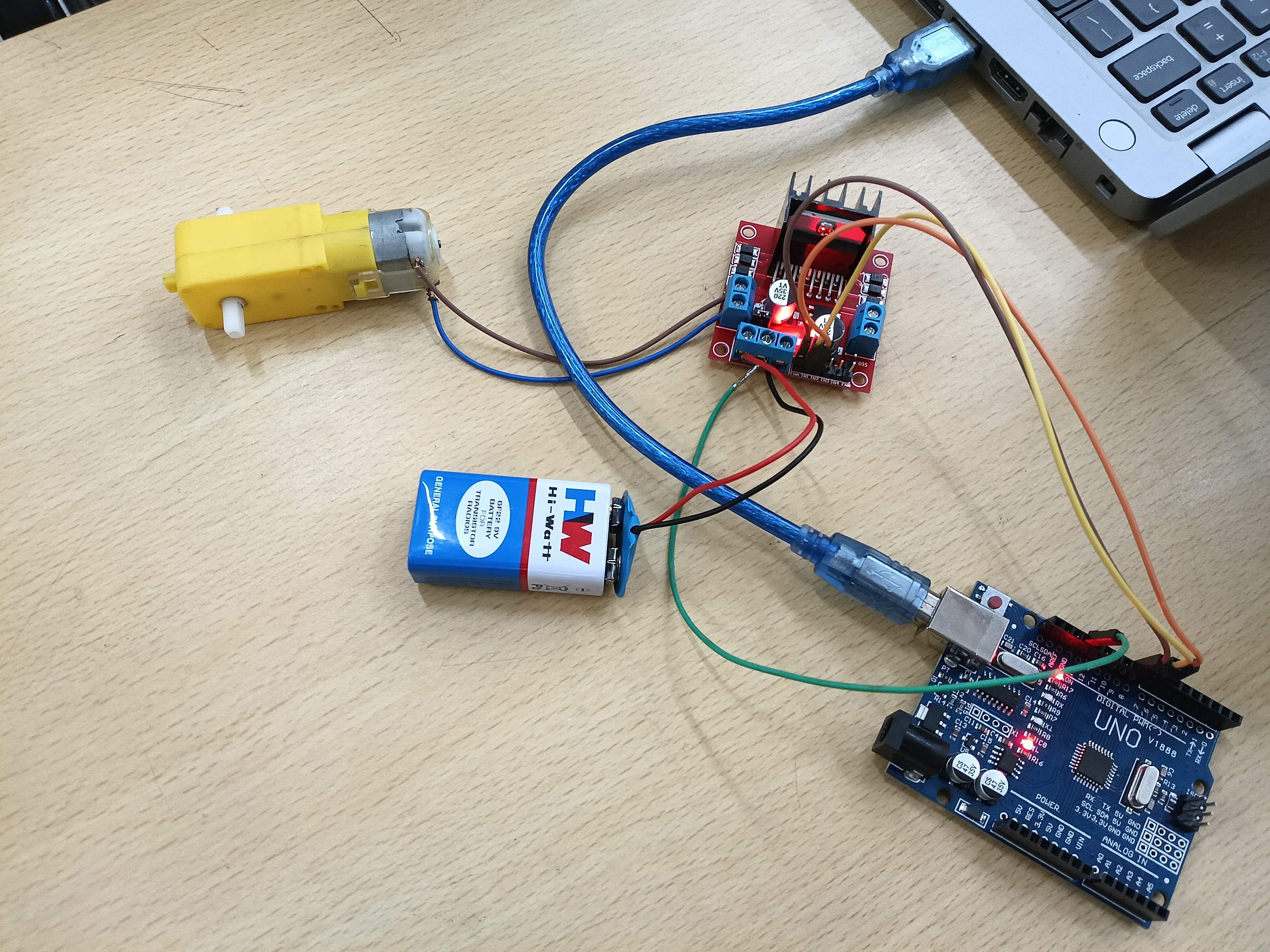
- The connections are as follows-
Outcomes & Learnings:
-
Components of a L298N motor driver:
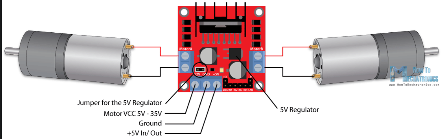
- The motor has two screw terminal blocks for the Mortor A and Motor B and the other screw terminal block is for the ground pin , VCC for motor and 5V pin which can be input or output.
- The 5V regulator can be either enabled or disabled using a jumper wire.
- if motor supply voltage < 12V we can enable the 5V regulator and it can be used as output.
- else if supply voltage > 12V then we have to disconnect the jumper as it will cause damage to internal components.
- Then there are 6 logic controlling inputs.
- The ENA (enable A) and ENB (enable B) pins are used to enable and control the speed of the motors. If a jumper is connected then the motor will be enabled and run at max. speed. If we remove the jumper and connect a PWM input (pulse width modulation) to this pin we can control the speed of the motor.Else if we connect this pin to the ground the motor will be disabled.
- The IN1 (input 1) and IN2 (input 2) pins are used to control the direction of motor A.
- similarly IN3 and IN4 are used to control the direction of motor B.
-
Note: The pins in L298N driver which are responsible for speed control are ENA & ENB, these pins should be compulsorily connected to the PWM (~) ports of the Arduino UNO, so that PWM takes place.
-
The speed of the motor can be easily controlled by just changing the input voltage to the motor. The most common method is using the PWM signal. PWM or Pulse Width Modulation is a technique which allows us to adjust the average value of the voltage which goes to the electric device (in this case L298N motor). The average voltage depends on the duty cycle, or the amount of time the signal is ON versus the amount of time the signal is OFF in a single period of time.
TASK 11: LED Toggle Using ESP32
Objective:Learn the working of an ESP32 and create a standalone web server with an ESP32 that controls the LED connected with ESP32 GPIOs(General Purpose Input/Output). Outcomes & Learnings:
-
The ESP32 is a low-cost, Wi-Fi-enabled microcontroller ideal for IoT projects. It’s powerful enough to handle web server tasks while remaining energy-efficient.
-
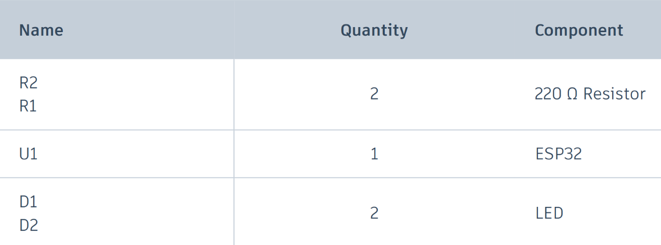
For this project I used the following components:
-
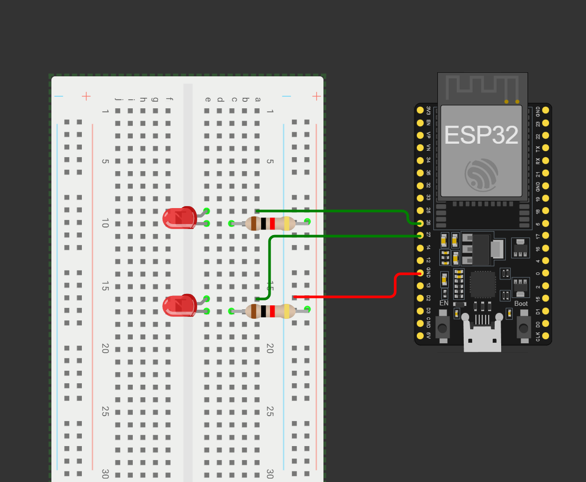
The connections made are as follows:
-
NOTE:LEDs require resistors to prevent excessive current flow, which can damage the LED or ESP32. A 330Ω resistor is suitable for most standard LEDs when using the ESP32’s 3.3V GPIO pins.
-
Once the code is successfully uploaded, launch the Serial Monitor in the Arduino IDE, setting the baud rate to 115200. Press the ESP32’s EN (reset) button. The ESP32 will establish a Wi-Fi connection and display its IP address in the Serial Monitor.
-
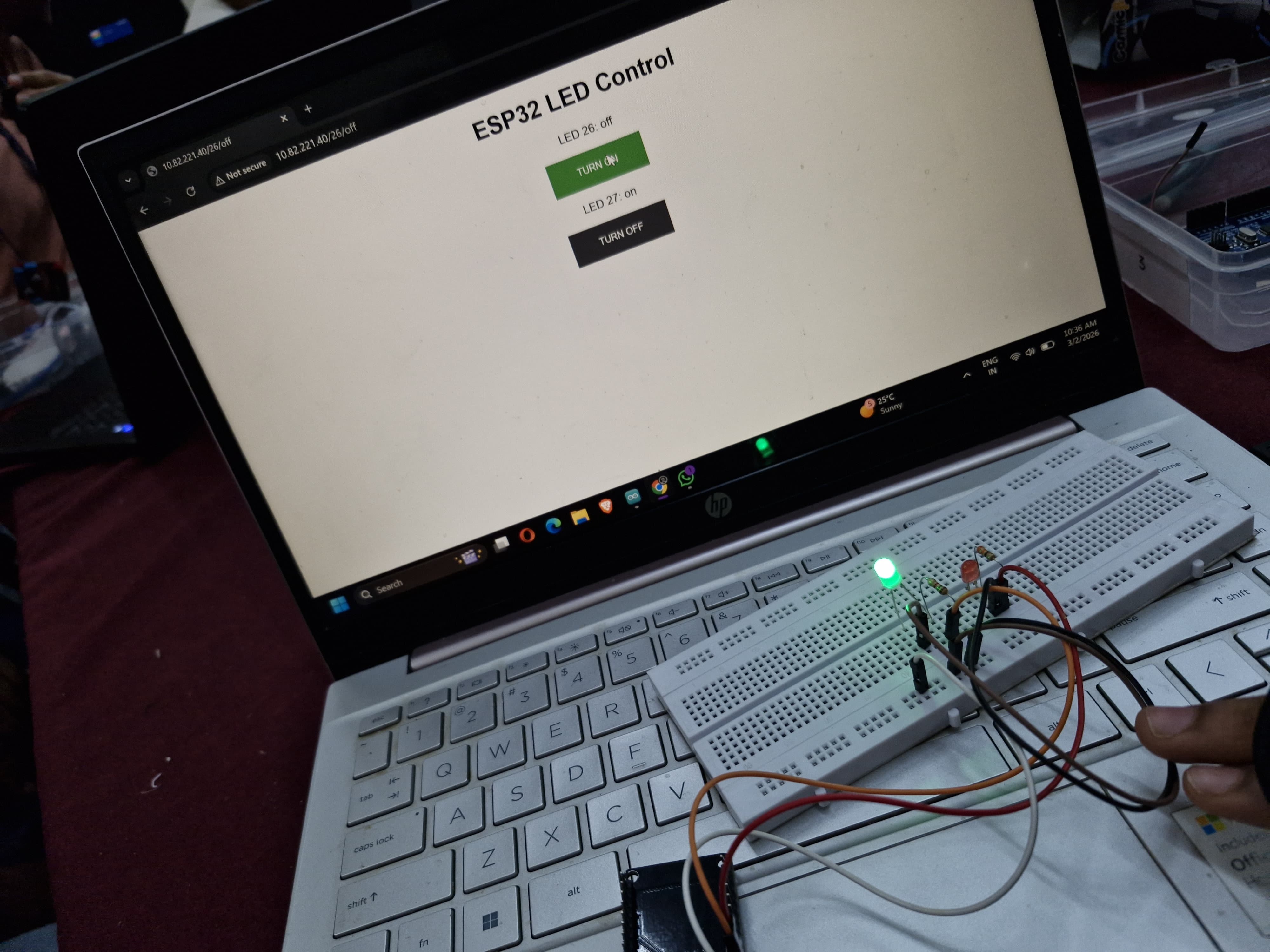
NOTE:Baud rate is the number of symbols (signal changes) transmitted per second in a communication channel, measured in Baud (Bd) or symbols per second. Enter this IP into any browser on a device connected to the same Wi-Fi. You’ll see a webpage with two buttons to control the LEDs.
-
Here is a picture and a video of me performing the task:
TASK 12: Soldering Prerequisites
Objective: Learn about the soldering equipment and perform basic soldering on a perf board, for example a LED circuit.
Outcomes & Learnings:
-
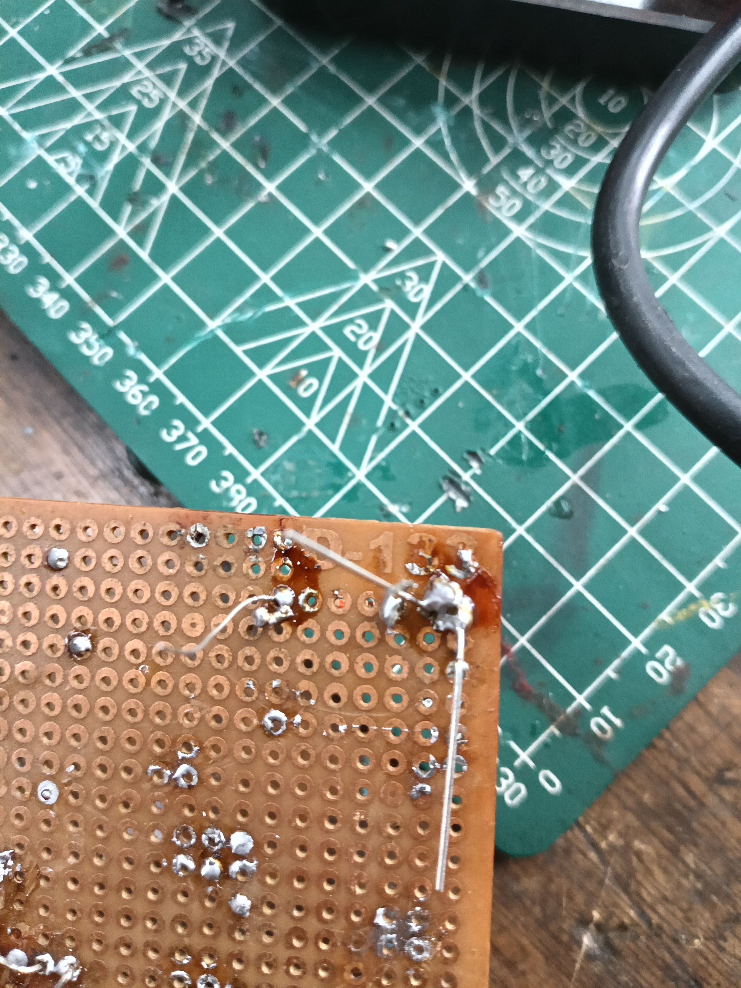
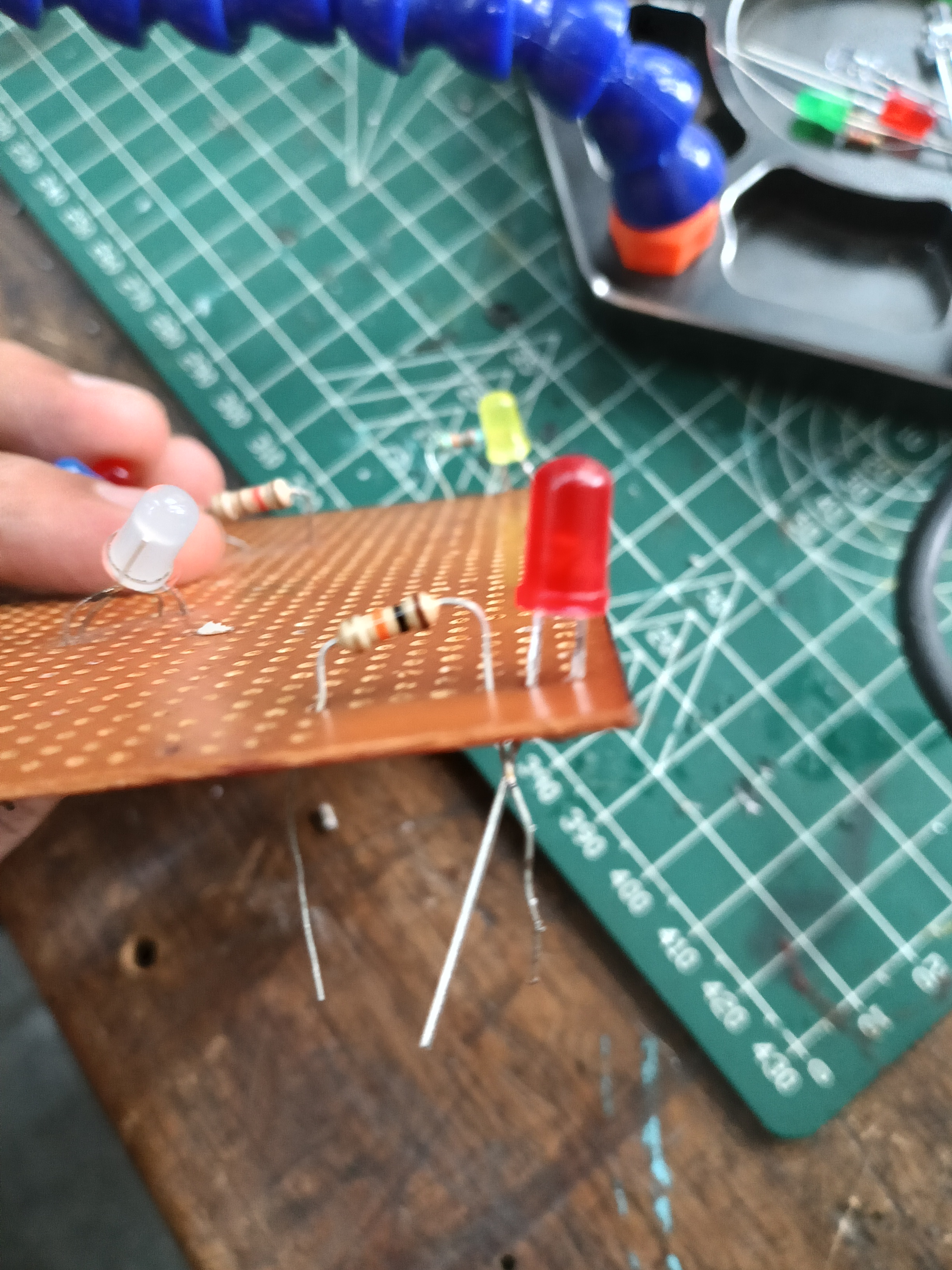
This was my first experience soldering and it was great. I soldered a LED with a resistor on a perf board,ensuring proper orientation.
-
Solder is a metal alloy material that is melted to create a permanent bond between electrical parts.For electronics soldering, the most commonly used type is lead-free rosin core solder. This type of solder is usually made up of a Tin/Copper alloy. Leaded 60/40 (60% tin, 40% lead) rosin core solder can also be used but it is becoming less popular due to health concerns.
-
Before soldering process is started the soldering iron needs to be prepare by tinning the tip with solder. This process will help improve the heat transfer from the iron to the item you’re soldering.
Step 1: Begin by making sure the tip is attached to the iron and screwed tightly in place.
Step 2: Turn on your soldering iron and let it heat up. If you have a soldering station with an adjustable temp control, set it to 400′ C/ 752′ F.
Step 3: Wipe the tip of the soldering iron on a damp wet sponge to clean it. Wait a few seconds to let the tip heat up again before proceeding to step 4.
Step 4: Hold the soldering iron in one hand and solder in the other. Touch the solder to the tip of the iron and make sure the solder flows evenly around the tip.
TASK 13: 555 IC astable multivibrator with 60% duty cycle
Objective: Design a 555 IC astable multivibrator with 60% duty cycle.
Outcomes & Learnings:
-
Multivibrator is the electronic circuit which is used to implement 2-state devices like oscillator,timer and flip-flop.Here 2 states refer to the voltage level(like +10v and 0v)or it can be either high(1) or low(0) state.There are 3 types- Astable,Monostable and Bistable multivibrators. In astable multivibrator the output will not remain stable in any of the two states, i.e continuously changes between the two states.
-
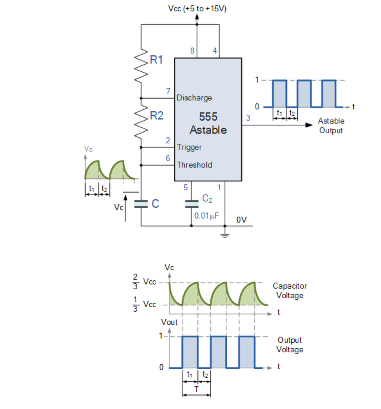
Circuit for this multivibrator:
-
Working of 555 timer:
- The 555 Oscillator is another type of relaxation oscillator for generating stabilized square wave output waveforms of either a fixed frequency of up to 500kHz or of varying duty cycles from 50 to 100%.
- As soon as the capacitor voltage reaches (2/3)rd of Vcc voltage, there will be a transition in the output from logic high(1) to logic low(0) value . Simultaniously the capacitor starts discharging to 0V. And as soon as the capacitor voltage reaches (1/3)rd of Vcc voltage, then again there will be a transition in the output from logic low(0) to logic high(1) value .
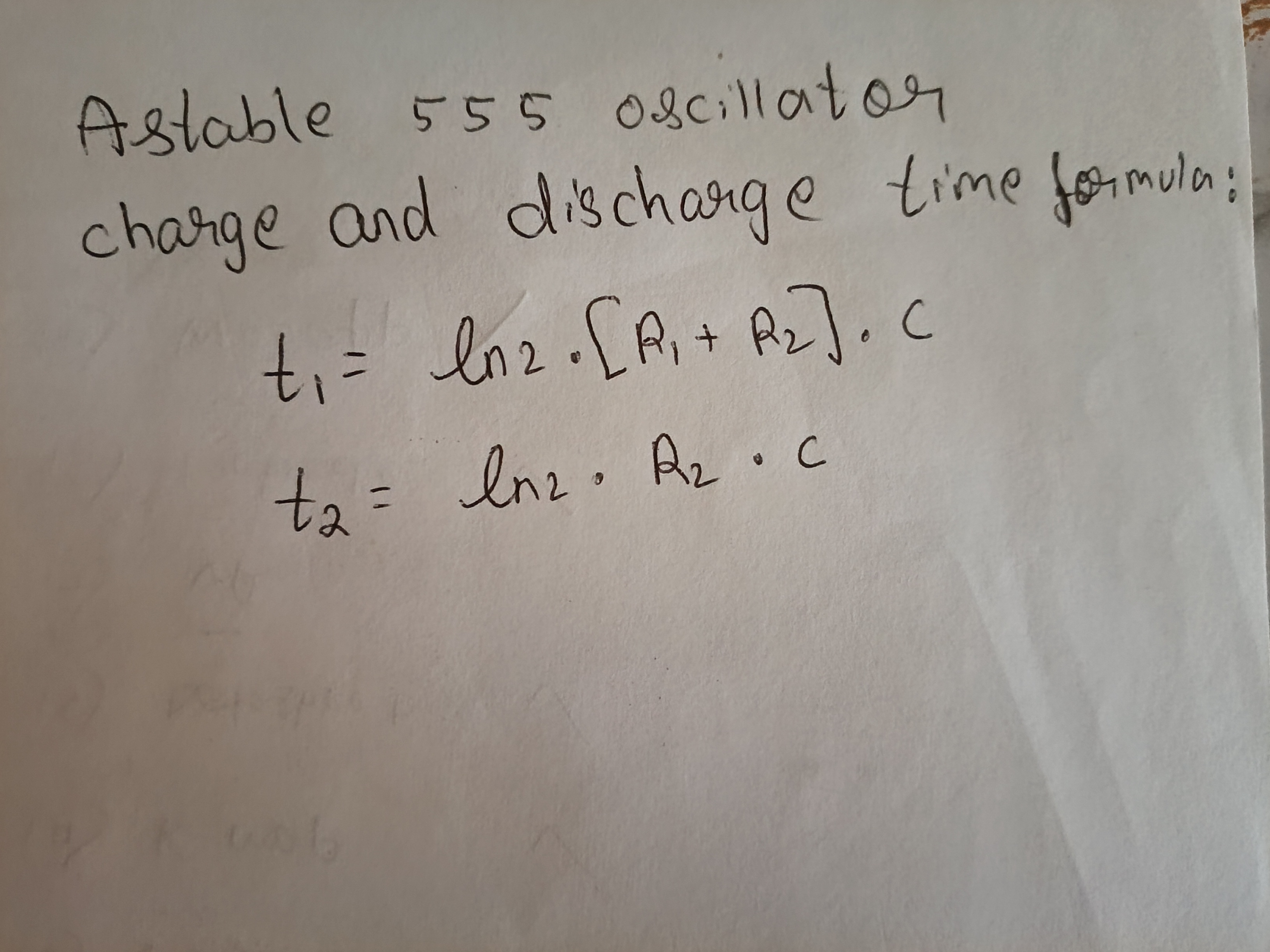
- Therefore, t1 is time where output voltage is high and t2 is time where output voltage is low. another notation is T(on) and T(off)
- By observing the formula we can infer that t1 > t2. Because during the charging, the resistor is charging through R1 and R2 but while discharging process it is discharging only through R2.
-
Components Used
- 555 IC Timer
- Capacitors (C1=10μF & C2=1μF )
- Resistors (R2=10kΩ & R1=4.7kΩ)
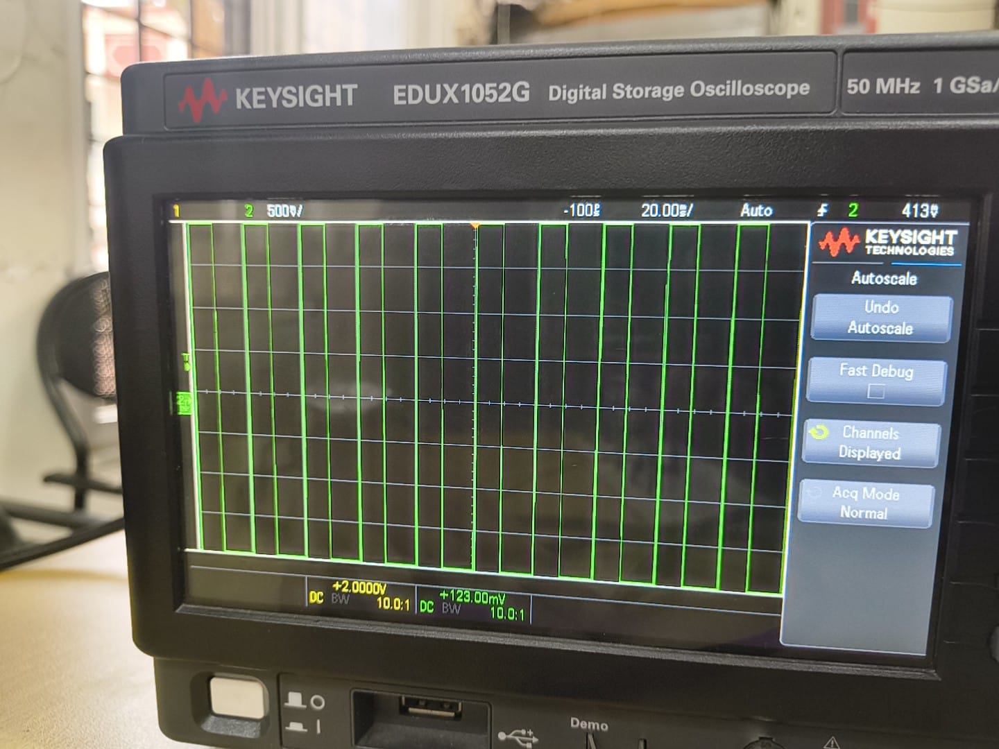
- Oscilloscope
-
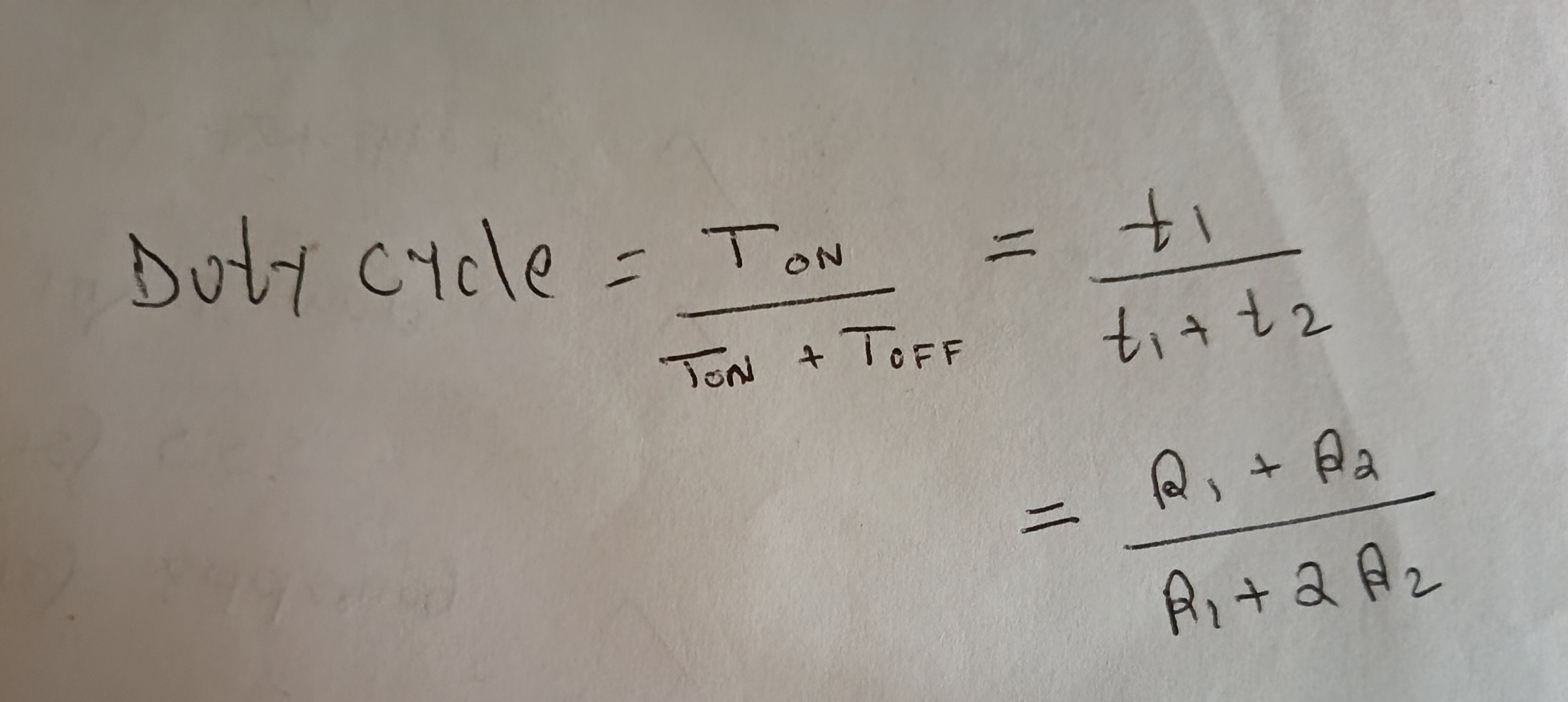
Duty cycle is the percentage of time a signal, device, or system spends in an active "ON" state compared to the total operating time. For these value the duty cycle obtained is 59.51% (which is almost equal to the required 60%)
TASK 14: Karnaugh Maps and Deriving the logic circuit
Objective:Determine the karnaugh map and make a burglar alarm using simple logic circuits. The buzzer or led blinks when certain conditions are met, you can use push buttons for the door and key.
Outcomes & Learnings:
-
Karnaugh Maps offer a graphical method of reducing a digital circuit to its minimum number of gates. The map is a simple table containing 1s and 0s that can express a truth table or complex Boolean expression describing the operation of a digital circuit. The map is then used to work out the minimum number of gates needed, by graphical means rather than by algebra
-
Constructing Karnaugh Maps: The shape and size of the map is dependent on the number of binary inputs in the circuit to be analysed. The map needs one cell for each possible binary word applied to the inputs.
 Where
(a) is 2 input circuits which require maps with 2^2 = 4 cells
(b) is 3 input circuits which require maps with 2^3 = 8 cells
(c) is 4 input circuits which require maps with 2^4 = 16 cells
Where
(a) is 2 input circuits which require maps with 2^2 = 4 cells
(b) is 3 input circuits which require maps with 2^3 = 8 cells
(c) is 4 input circuits which require maps with 2^4 = 16 cells -
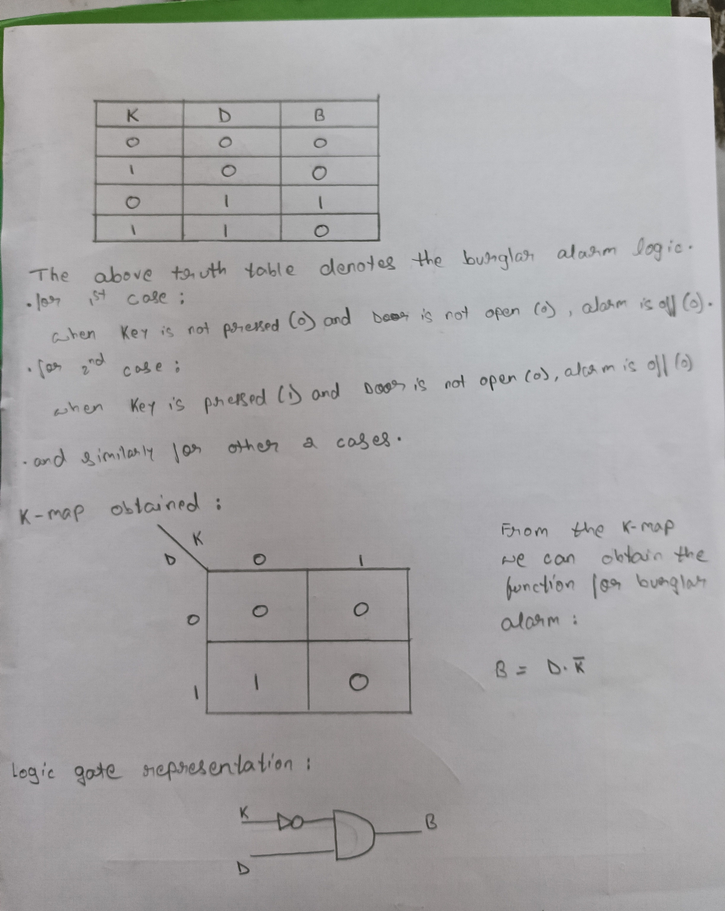
To make a burglar alarm, we need to first define the inputs and the logic that triggers the alarm.The alarm should ring when the door is opened without the key. So,
- let D(Door) be 0 when closed and 1 when it is open.
- let K(Key) be 0 if it is not pressed(or put on the door) and 1 if it is pressed.
- let B(Burglar alarm) be 0 when it is off and 1 when alarm is on.
TASK 15: Active Participation:
I participated in Impetus 26.0 under the event CTRL + Z, which focused on reverse prompt engineering. The challenge involved analyzing AI-generated outputs and designing prompts to reproduce similar results.
TASK 16: Datasheets report writing:
Objective: Study the datasheet of L293D motor driver and write a report on it. Specify about the ICs used in L293D, PWM, H-bridge etc
Outcomes & Learnings:
- What is a Motor Driver?
Motor driver acts as an amplifier that coverts the low current signal to high current signal which helps to drive the motor.
- Why is a Motor Driver necessary?
So suppose we have a motor that runs on 12V and draws current of 1amp and we want to run it with the help of a micro-controller, but most micro-controller like arduino uno /nano can only provide only 5V of output whereas raspberry-pi can only provide only 3.3V of output. Due to this the motor will not run at full potential. Here is where a motor driver come in which amplifies the control signal by use of external power and sends it to the motor.
-
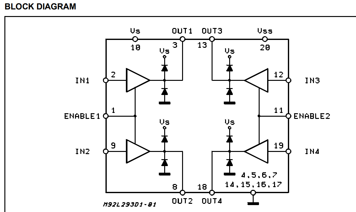
The L293D is a dual-channel H-Bridge motor driver capable of driving a pair of DC motors or a single stepper motor. Which means it can drive upto two motors individually.Since the L293D has two H-bridges, it can control the two independent wheels (left and right) of a small robotic car, allowing it to move forward, backward, and turn.

-
The H-Bridge Architecture The spinning direction of a DC motor can be controlled by changing the polarity of its input voltage. A common technique for doing this is to use an H-bridge. An H-bridge circuit consists of four switches with the motor in the centre forming an H-like arrangement. Closing two specific switches at a time reverses the polarity of the voltage applied to the motor. This causes a change in the spinning direction of the motor

- Speed Control via PWM Speed control is achieved through Pulse Width Modulation (PWM), usually applied to the Enable pins.This pin acts as a master switch. When HIGH, the motor runs based on the Input pins. When LOW, the motor stops completely regardless of the Inputs.The average voltage is proportional to the width of the pulses known as the Duty Cycle.
Task 17: Introduction to VR
Objective:Familiarise yourself with what Virtual Reality is. Make a detailed study about what's the difference between VR and AR. Mention about the trends in the space and technology stack being developed. Make about Indian companies in this space. Make the report with detail.
Outcomes & Learnings:
click here to view the report