
BLOG · 12/4/2023
Common Tasks Report
A Brief Report of the common tasks done by Shriram Rayakar

This Article is yet to be approved by a Coordinator.
BLOG · 12/4/2023
A Brief Report of the common tasks done by Shriram Rayakar
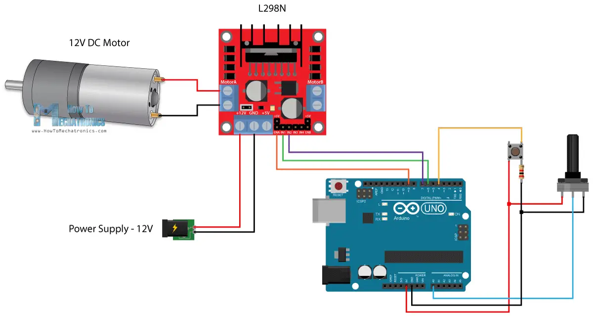 \n \nAfter connecting, the code is uploaded to the Arduino through Arduino IDE from a computer. Now the speed can be controlled by the potentiometer and the direction through Push Button.\n \n\n
 \n<iframe height="\315"">\n\n \n\n \n\n\n\n---\n---\n---\n---\n---\n---\n---\n---\n---\n---\n---\n \n\n---\n---\n---\n\n\n\n# Task-2: LED Toggle Using ESP32\n---\n \n\n \n\nThe aim of this task was to create a standalone web server with an ESP32 that controls the LED connected with ESP32 GPIOs using the Arduino IDE.\n \n\n \n\n Skills learnt: Basic working and application of ESP32 and Arduino IDE.\n \n\n \n\n\n This was a simple experiment which gave an insight into IOT. Two LEDs are connected to the ESP32 microcontroller.\n\n
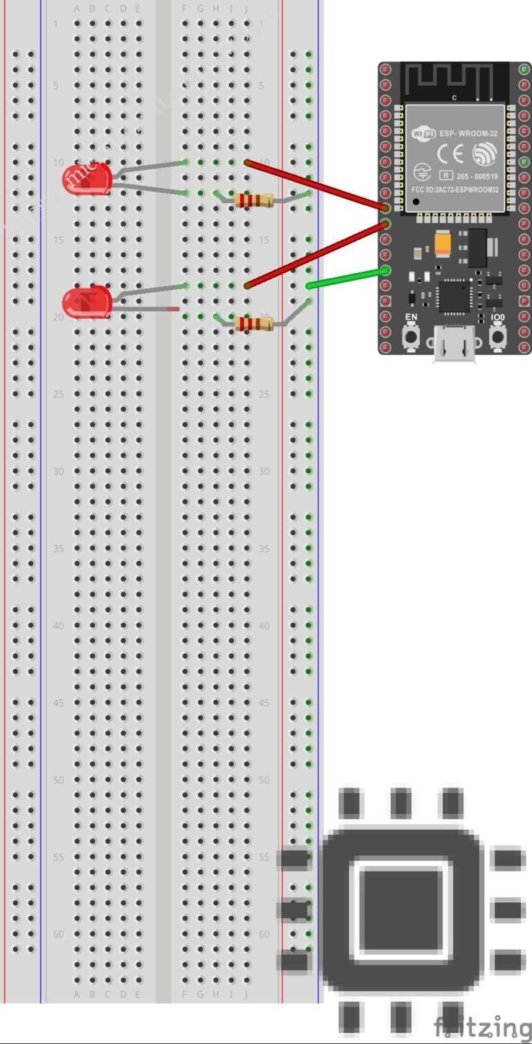 \n \n\n \n\nThen the code is uploaded to the ESP32 and it gets connected to a local LAN network. The LEDs can be controlled by any wifi-enabled device connected to the same LAN.\n\n
 \n \n\n \n\n
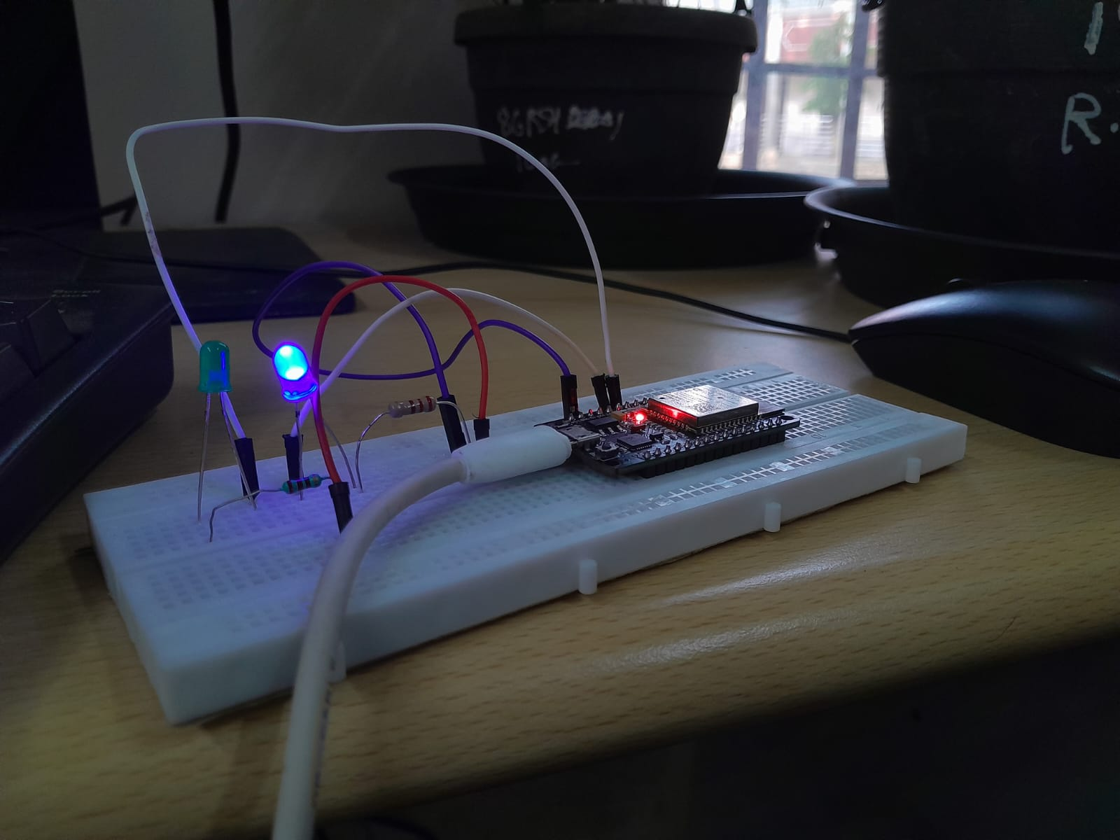 \n\n \n\n \n\n\n\n---\n---\n---\n---\n---\n---\n---\n---\n---\n---\n---\n \n\n---\n---\n---\n\n\n# Task-3: Working with GITHUB\n---\n \n\n \nThe aim of this task was to learn the basics of contributing to a project., as it is one of the main software used for hosting of software development and version control.\n \n\n \n\n\n Skills learnt: Cloning, Problem rectification, Merging of repos creating pull requests.\n \n\n \n\n\n A demo repository was written in python and a small problem was given. The repo had to be forked and cloned into the local computer to debug. After the changes have been made, it had to be committed and pushed to the forked repo. Then a pull request had to be created from the main repository. After it got approved, the changes would be reflected in the main repository.\n \n\n \n\n
  \n \n\n \n\n \n
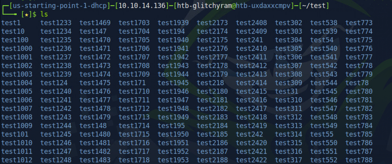
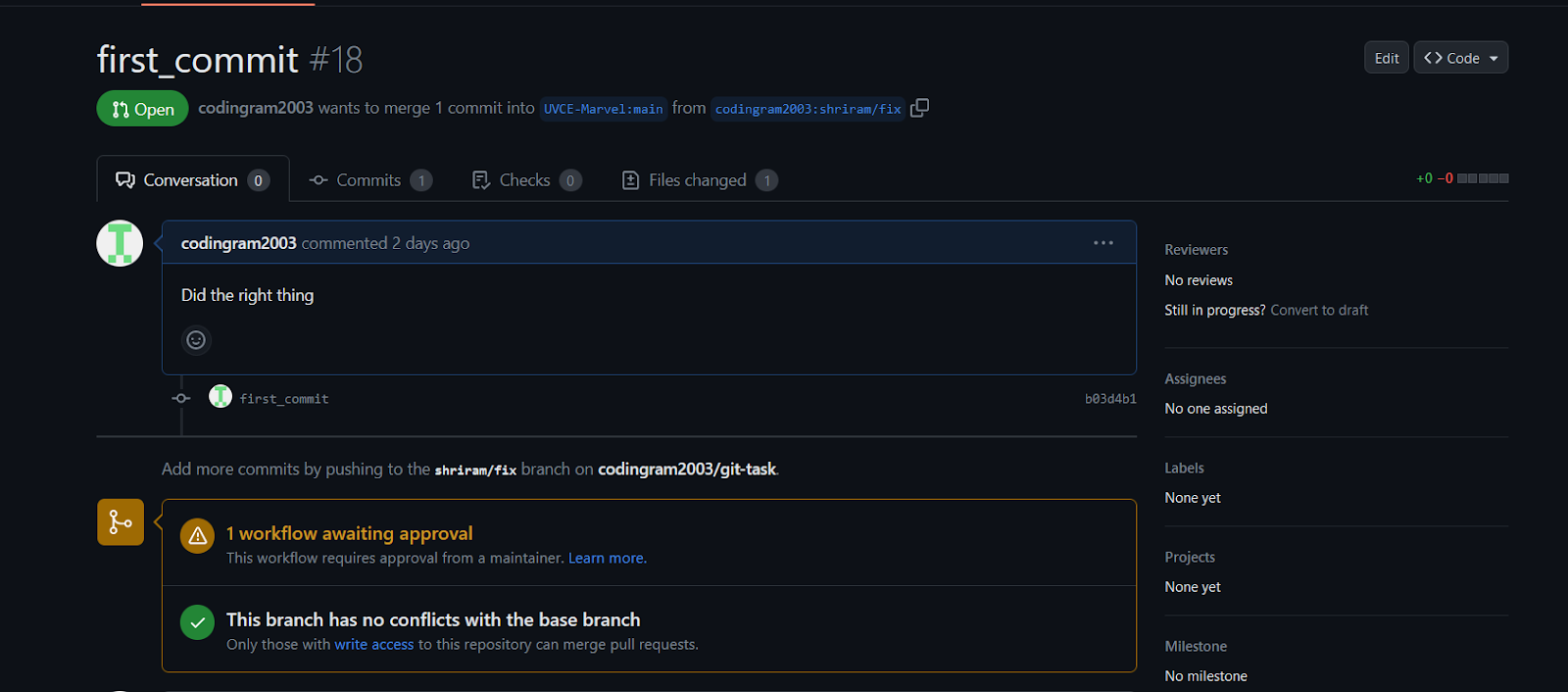 \n \n \n\n \n\n\n\n---\n---\n---\n---\n---\n---\n---\n---\n---\n---\n---\n \n\n---\n---\n---\n\n\n \n\n# Task-4: Get familiar with the CLI on Ubuntu\n---\n \n\n \n\nThe aim of the task was to get familiar with the Command Line Interface on Ubuntu, as it is one of the simple and efficient ways to work with cloud service providers and servers.\n \n\n \n\n\n Skills learnt: Bash basics, Some basic functionalities of CLI.\n \n\n \n\n\n A folder named test was created and changed the current directory to that folder using ‘cd’ command.Created a blank text file using ‘touch’ command. Then the files and folders were listed using ‘ls’ command. Then 2600 folders were created using bash script and ‘mkdir’ command. Finally two files are concatenated using ‘cat’ and ‘>>’ and displayed in the terminal.\n \n\n \n\n
 \n \n\n \n\n
 \n \n \n\n \n\n\n\n---\n---\n---\n---\n---\n---\n---\n---\n---\n---\n---\n \n\n---\n---\n---\n\n\n \n\n# Task-5: Writing Resource Article using Markdown\n---\n \n\nThe aim of this task was to learn how to write articles in MarkDown (.md) and posting it on the Marvel website.\n \n\n \n\n\nSkills learnt: MD format of writing and its importance.\n \n\n \n\n\n Markdown is an easy-to-use markup language that is used with plain text to add formatting elements (headings, bulleted lists, URLs) to plain text without the use of a formal text editor or the use of HTML tags. Markdown is device agnostic and displays the writing format consistently across device type.\n \n\n \n\n \n
 \n \n\n \n\nThe article was written using appropriate markdown attributes like headings (#). Then it was posted on the MARVEL website.\n \n\n \n\n \n\n\n\n---\n---\n---\n---\n---\n---\n---\n---\n---\n---\n---\n \n\n---\n---\n---\n\n \n\n# Task-6: Tinkercad\n---\n \n\nThe aim of this task was to simulate a circuit in TinkerCAD, using some basic circuit elements and Arduino.\n \n\n \n \n\nSkills learnt: Working with Tinkercad, Arduino working, Live circuit simulation with varying conditions and problem solving skills.\n \n\n \n\n Tinkercad is an online 3D modeling program that runs in a web browser.\n \n\n \n\n
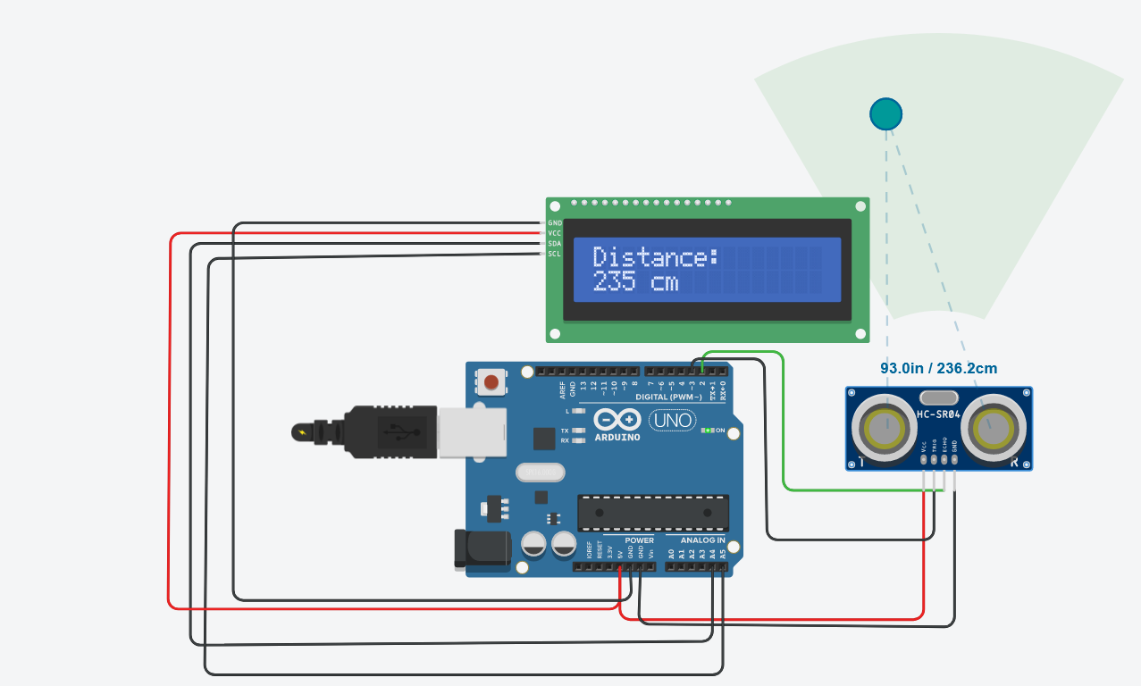 \n \n\n \n\nUltrasonic Sensor is a device which senses the distance with the echo of sound waves. This was connected to the Arduino board. Then the code was written so that the LCD display connected to board will show the distance.\n \n\n \n\n<iframe height=""315"">\n \n\n \n\nSimulation Link: Ultrasonic Distance Sensor\n \n\n \n\n \n\n\n\n---\n---\n---\n---\n---\n---\n---\n---\n---\n---\n---\n \n\n---\n---\n---\n\n \n\n\n\n# Task 7: API\n---\n \n\nThe aim of this task was to understand the working and importance of APIs in digital information transactions.\n \n\n \n\nSkills learnt: Meaning and importance of the API, its usage and practical application.\n \n\n \n\nApplication - Programming Interface [API] is a tool used while programming/developing web applications, apps or setting up servers to transact data between electronic devices. APIs are used to integrate new applications with existing software systems. This increases development speed because each functionality doesn't have to be written from scratch.\n \n\n \n\nA web-application named Havaamaan was developed using HTML, CSS and Javascript. API was used here to get the weather info of the city entered by the user and then it was displayed.\n \n\n \n\n
 \n\n \n\n<iframe height=""315"">\n \n\n \n\nGITHUB Repository: HAVAAMAAN\n \n\n \n\n \n\n\n\n---\n---\n---\n---\n---\n---\n---\n---\n---\n---\n---\n \n\n---\n---\n---\n\n \n\n# Task-8: Soldering \n---\n \n\nThe aim of this task was to solder a circuit element into a circuit board.\n \n\n \n\nSkills learnt: Working and role of tools and elements used in Soldering, The process of soldering.\n \n\n \n\nSoldering is the process of joining two or more electronic parts together by melting solder around the connection. Solder is a metal alloy and when it cools it creates a strong electrical bond between the parts.\n \n\n \n\n
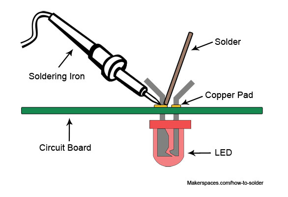 \n \n\n \n\nThe circuit board was fixed into Helping Hand which has alligator clips to hold the board. Then the the element to be soldered was inserted into the holes in the board. Then the soldering iron was turned on and once it was hot enough, it was brought near the copper pad around the hole. Solder was also brought nearer and then it melted and got deposited in the gap between the ends of the circuit element, fixing it on the circuit board.\n \n\n \n\n<iframe height=""315"">\n \n\n \n\n \n\n\n\n---\n---\n---\n---\n---\n---\n---\n---\n---\n---\n---\n \n\n---\n---\n---\n\n \n\n\n# Task 9: Design a 555 astable multi-vibrator\n---\n \n\nThe aim of this task was to understand the working of IC 555 and to make an astable multi-vibrator using the same.\n \n\n \n\n \nSkills learnt: IOs of IC 555, its application as Astable Multi-vibrator\n \n\n \n\nWe can connect the 555 timer IC in an Astable mode to produce a very stable 555 Oscillator circuit for generating highly accurate free running wave-forms whose output frequency can be adjusted by means of an externally connected RC tank circuit consisting of just two resistors and a capacitor.\n \n\n \n\nIC 555 was connected in the figure given below:\n \n\n \n\n
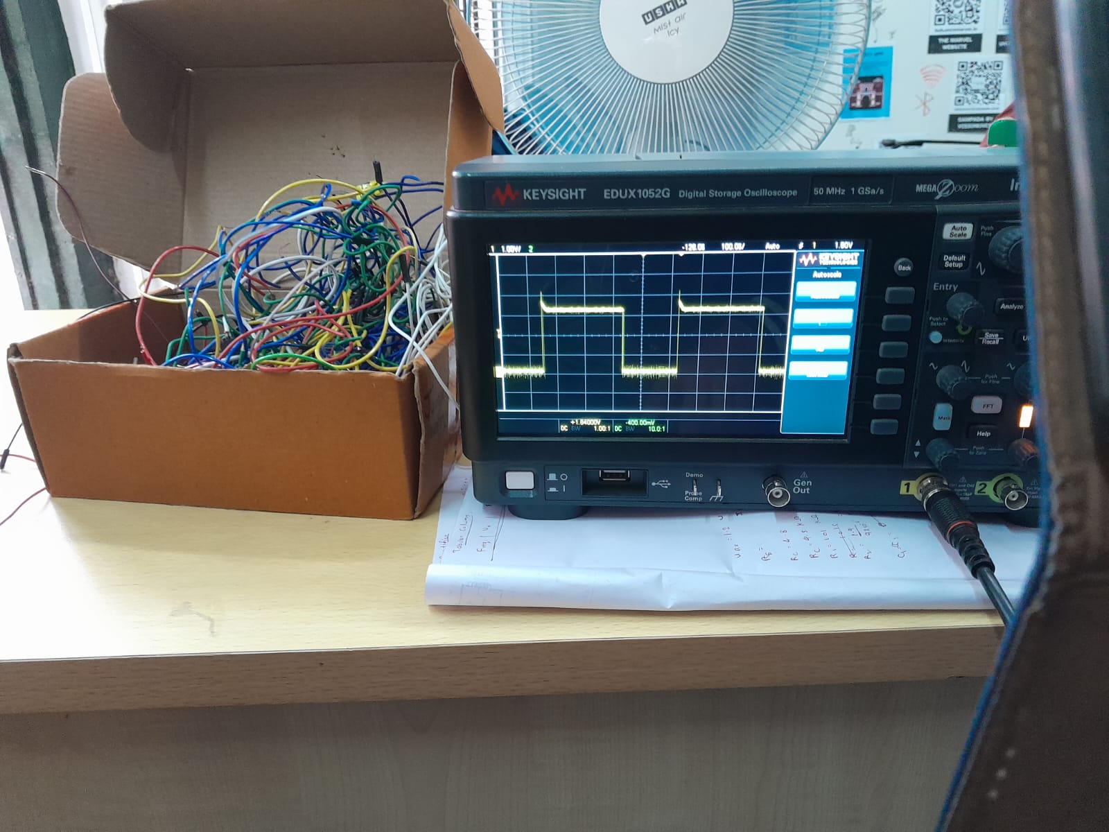
 \nThe values of R1 and R2 were calculated using:\n \n\n \n\n
 \n \n\n \n\nThen output was taken and displayed in a Oscilloscope.\n \n\n \n\n
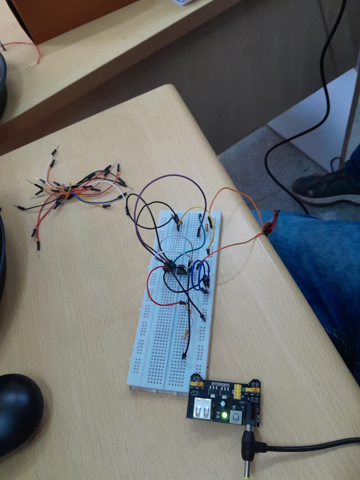
 \n \n\n \n\n \n\n\n\n---\n---\n---\n---\n---\n---\n---\n---\n---\n---\n---\n \n\n---\n---\n---\n\n \n\n# TASK 10: Karnaugh Maps and Deriving the logic circuit\n---\n \n\nThe aim of the task was to get familiar with Karnaugh Maps [K-Maps] and design a circuit to show burglar entry through an alarm using Logic Gates.\n \n\n \n\n\nSkills Learnt: Working and role of K-maps, Writing an equation to satisfy conditions, designing a logic circuit using an equation.\n \n\n \n\nK-mapping is a simple and efficient way to get a logic equation using truth tables. \n \n\n \n\nA truth table was written according to a scenario. The scenario was to sound an alarm when the door is open but the key is not pressed. After the truth table was written, using K-mapping, an equation was written. Finally it was used to design a logic circuit using Logic Gates.\n \n\n \n\n
 \n\nSimulation Link: Burglar Alarm\n \n\n \n\n \n\n\n\n---\n---\n---\n---\n---\n---\n---\n---\n---\n---\n---\n \n\n---\n---\n---\n\n \n\n# TASK 11: Active Participation\n---\n \n\nThe aim of this task was to get certified in a particular field and participating in an event.\n \n\n \n\n\nSkills Learnt: Use of APIs and Tinkercad.\n \n\n \n\nI participated in an event called Tech-Roadies which was organized as a curtain-raiser for the Impetus 23.0 . Its rounds were spanned over different engineering domains, which helped me understand the scope and importance of other branches.\n
 \n\n\n"