
BLOG · 14/9/2025
Level 0 reprt part 2
A continuation of my report

TASK 11: LED Toggle Using ESP32
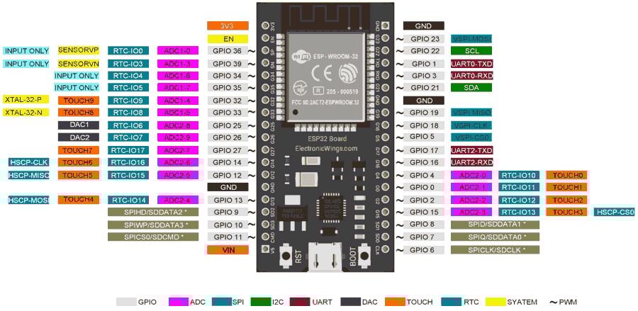
Objective: Learn the working of an ESP32 and create a standalone web server with an ESP32 that controls the LED connected with ESP32 GPIOs.
I learned how to use the ESP32 microcontroller, which comes with built-in Wi-Fi, to set up a simple web server. Through this server, an LED connected to the ESP32 can be controlled remotely using a smartphone or computer by accessing it via a web browser. The smartphone or computer and the ESP32 have to be connected to the same wifi source.
Working Process:
-
First, the Arduino IDE must be prepared to work with the ESP32.
This involves: Installing the ESP32 board package from the Board Manager. Selecting the correct board type (e.g., ESP32 Dev Module) in the Tools → Board menu. Installing any required libraries to handle Wi-Fi and web server functionality.(wifi.h) -
Writing the ESP32 Program
In the Arduino IDE, a program (sketch) is written to turn the ESP32 into a web server.
Key functions of the code:
  -Connect the ESP32 to a specified Wi-Fi network using the SSID and password.

  -Assign or obtain an IP address for the ESP32 on that network.

  -Listen for incoming HTTP requests from clients (browsers).
3. Setting Up the Web Page
The ESP32 serves a simple HTML web page stored in its memory.
When the ESP32’s IP address is entered into a browser, this web page is displayed.

The page contains:

An ON button

An OFF button
These buttons are linked to specific web server routes (/on and /off) that trigger actions on the ESP32.
- Handling User Input
When the user clicks the ON button:
The browser sends a request to the ESP32 web server.

The ESP32 processes this request and sets the GPIO pin HIGH, turning the LED ON.

When the user clicks the OFF button:

A request is sent to the ESP32.

The ESP32 sets the GPIO pin LOW, turning the LED OFF.

This real-time interaction allows remote control of hardware via a web interface.
- Hardware Interaction
The LED is connected to one of the GPIO pins of the ESP32.
Based on the web requests:

HIGH signal → LED turns ON

For the regression model using Sci-kit Learn. [Click here](https://github.com/Souparno-Baidya/Linear-Regression-)
LOW signal → LED turns OFF
TASK 12: Soldering prerequisites
Objective: Learn about the soldering equipment and perform basic soldering on a perf board, for example a LED circuit.
My first experience soldering an LED onto a perf board was amazing. I inserted the LED leads through the correct holes, ensuring proper orientation. Then, I heated the soldering iron and kept it on the junction of the lead and copper pad, feeding solder wire into the joint for a solid connection. Later cross checked if the connections were strong. I learnt about accessoriesuchas sponge and flux. We were also explained about how soldering is done on PCB boards and controller chips.


TASK 13: 555 IC astable multivibrator with 60% duty cycle
Objective: Design a 555 IC astable multivibrator with 60% duty cycle.
The components required fot this task are :
| Name | Component | Quantity |
|---|---|---|
| U1 | 555 IC Timer | 1 |
| C1 | 0.01 µF Capacitor | 1 |
| C2 | 0.01 µF Capacitor | 1 |
| R1 | 10 kΩ Resistor | 1 |
| R2 | 20 kΩ (10k + 10k) | 1 |
| V1 | VRPS – 5V Supply | 1 |
The connections are made on the breadboard as shown in the circuit diagram below:

The DSO will display a pulse with a 60% high time and 40% low time, reflecting the 60% duty cycle. The frequency of the pulse depends on your resistor and capacitor values.
Duty cycle Expected-60%.My task outcome-59.87%
From calculations R1:R2=1:2


Task 14 : K-Map & Deriving Logic Gates
Objective: Determine the Karnaugh map and make a burglar alarm using simple logic circuits. The buzzer or led blinks when certain conditions are met, you can use push buttons for the door and key.
The burglar alarm system is an electronic circuit that detect unauthorised entry and rings the alarm.
This system activates the alarm when the door is open and the key is not pressed. The alarm works on the basis of the following table:

D denotes the Door.

D=0 denotes Closed Door, D=1 denotes Open Door.

K denotes the Key.

K=0 denotes Key is not put on the Door, K=1 denotes Key is put on the Door.

A denotes the Burglar Alarm.

A=0 means Alarm is OFF whereas A=1 means Alarm is activated.
The K-map obtained from the above truth table is :
Task 15 : Active Participation
I participated in the National space hackathon. IT was held in March-April. So we had to make a system that to analyze things being brought to the ISS and according to the storage system arrange them properly.
Main objective was:
Managing cargo on the ISS consumes nearly 25% of astronaut time due to manual stowage and retrieval. Our solution proposes an Automated Stowage & Retrieval System (ASRSS) that uses RFID/QR tags, a local inventory database, and optimization algorithms to recommend efficient storage locations and guide retrieval. A user-friendly tablet app enables quick search, slot suggestions, and step-by-step retrieval assistance. The system reduces errors, saves time, and syncs with ground servers for mission-wide visibility. By automating routine tasks while keeping astronauts in the loop, ASRSS can significantly improve efficiency, reduce workload, and enhance safety in space station logistics.

Task 16 : Datasheets report writin
Objective: Study the datasheet of L293D motor driver and write a report on it. Specify about the ICs used in L293D, PWM, H-bridge etc.

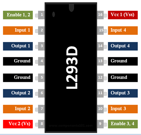
The L293D is a dual-channel H-Bridge motor driver capable of driving a pair of DC motors or a single stepper motor. This means it can drive up to two motors individually which makes it ideal for building a two-wheeled robotic platform. The L293D is most often used to drive motors, but can also be used to drive any inductive load such as a relay solenoid or large switching power transistor. It is capable of driving four solenoids, four uni-directional DC motors, two bi-directional DC motors or one stepper motor. The IC also includes built-in kick-back diodes to prevent damage when the motor is de-energized.
The L293D IC has a supply range of 4.5V to 36V and is capable of 1.2A peak output current per channel, so it works very well with most of our motors.
| Components | Range |
|---|---|
| Motor output voltage | 4.5V - 36V |
| Logic input voltage | 5V |
| Output Current per channel | 600mA |
| Peak Output Current per channel | 1.2A |
The following images shows the L293D pins:
PWM – to control speed:
The speed of a DC motor can be controlled by changing its input voltage. A common technique to do this is to use PWM (Pulse Width Modulation). PWM is a technique where the average value of the input voltage is adjusted by sending a series of ON-OFF pulses. The average voltage is proportional to the width of the pulses known as the Duty Cycle. The average voltage is proportional to the width of the pulses known as the Duty Cycle.
H-Bridge – to control the rotation direction:
The spinning direction of a DC motor can be controlled by changing the polarity of its input voltage. A common technique for doing this is to use an H-bridge. An H-bridge circuit consists of four switches with the motor in the centre forming an H-like arrangement. Closing two specific switches at a time reverses the polarity of the voltage applied to the motor. This causes a change in the spinning direction of the motor.
Task 17 : Introduction to VR
My first experience with VR was mind-blowing! It felt like stepping into a whole new world. We played games and the Lab had option to switch to so many worlds. We coud even see Human Anatomy in detail.
For my report on VR Click here
Tak 18 : Sad servers
Objective : To learn linux terminal commands and use them to solve command line murders.
Exact functions and usage of linux commands in terminal.
pwd(print working directory): Prints the current directory in the next line.

cd(change directory): Changes the directory into a given directory. Needs one argument.

ls(list): Lists the given directory.

grep : searches any given word in the files.Requires two arguments, one is the word and one more the location.

head: Used to display the first certain lines in the file.

-n: Used to limit printing.

cat: used to display files.

echo: used to input text into a file.
After 3 times trying i finally did find the solution.

Task 19 : Web app
Objective : To learn how to make a basic web app
The task was to create a simple web app. I built a To-Do tasks app where I can add tasks and manage them. The main difference between a website and webapp is that webapp is interactive portal where we can do particular task. Website is a place from where we can collect information.
For viewing the web app click here

For the updated ML tasks Click here