
BLOG · 12/4/2023
COMMON TASK REPORT -1
the post is about the report of the provided any 9 common task out of 15 is available here

TASK 1: Distance Measurement Using Ultrasonic Sensor and Arduino
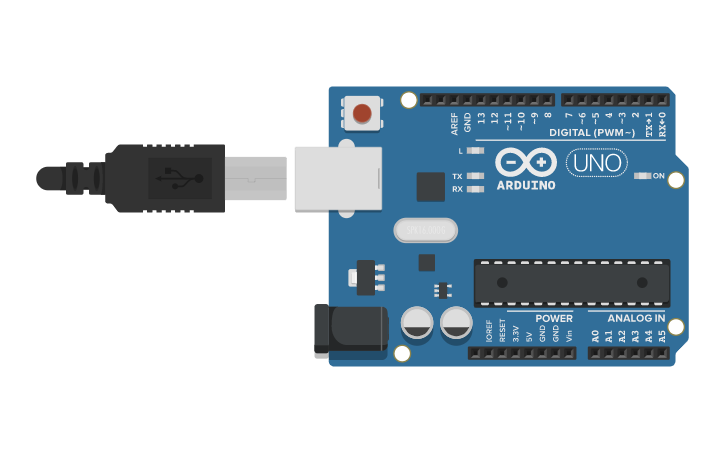
Arduino
Arduino is an open-source electronic platform based on the ATmega328 8-bit microcontroller. It can read input from various sensors and send instructions to control outputs. The Arduino IDE allows us to write code and interface hardware like Arduino boards and sensors.
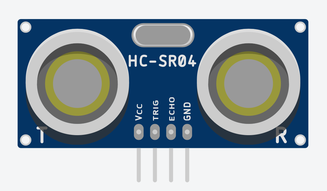
Ultrasonic Sensor
An ultrasonic sensor measures the distance between the sensor and an object without physical contact. It uses time-to-distance conversion based on the speed of sound.
Working Principle
Ultrasonic sensors work by emitting sound waves and receiving the echo from a reflected surface.
Formula:
Distance = Speed × Time
The speed of sound in air is approximately 344 m/s.
In the code:
durationstores the total time for the sound wave to travel to the object and back.- To get the one-way distance:
Distance = (Speed of Sound × Time) / 2
Components Required
- Arduino Uno R3 board
- Ultrasonic sensor (HC-SR04)
- 16x2 LCD display
- Jumper wires
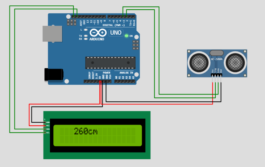
Procedure
- Connect Echo pin of sensor to D2 of Arduino.
- Connect Trigger pin of sensor to D3 of Arduino.
- Connect Vcc of sensor to 5V on Arduino.
- Connect GND to GND.
- Connect LCD Display:
- SDA to Arduino SDA
- SCL to Arduino SCL
- GND to GND
Arduino Code (Ultrasonic + LCD Display)
#include

LiquidCrystal_I2C lcd(0x20, 16, 2);

#define echoPin 2
#define trigPin 3

long duration;
int distance;

void setup() {
  lcd.init();
  lcd.backlight();
  pinMode(trigPin, OUTPUT);
  pinMode(echoPin, INPUT);
  Serial.begin(9600);
  Serial.println("Distance measurement using Arduino Uno");
  delay(500);
}

void loop() {
  digitalWrite(trigPin, LOW);
  delayMicroseconds(2);
  digitalWrite(trigPin, HIGH);
  delayMicroseconds(10);
  digitalWrite(trigPin, LOW);

  duration = pulseIn(echoPin, HIGH);
  distance = duration * 0.0344 / 2;

  Serial.print("Distance: ");
  Serial.print(distance);
  Serial.println(" cm");

  lcd.clear();
  lcd.setCursor(0, 0);
  lcd.print("Distance:");
  lcd.setCursor(0, 1);
  lcd.print(distance);
  lcd.setCursor(4, 1);
  lcd.print("cm");

  delay(100);
}
Applications
- RADAR systems
- Non-contact distance measurement
- Security systems and object detection
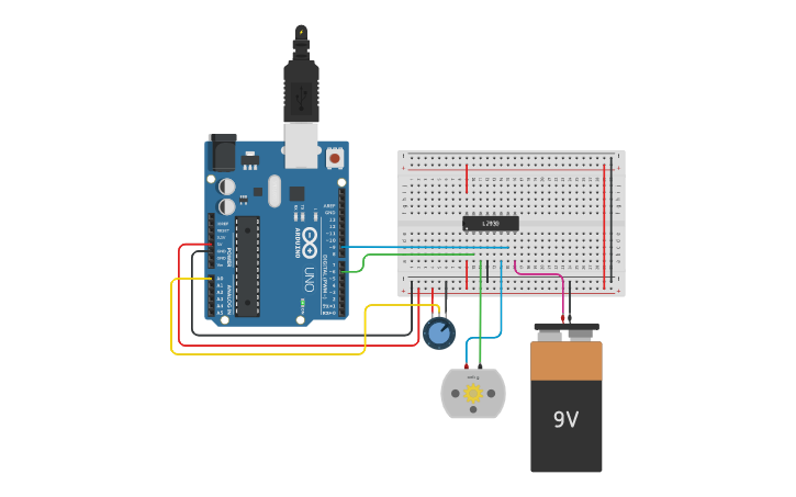
TASK 2: Speed Control of DC Motor
Overview
We can control the speed of a DC motor by varying its input voltage using Arduino and L298N Motor Driver.
Materials Required
- 12V DC Motor
- L298N Motor Driver
- Arduino Uno
- Potentiometer
- Push button
- Power supply
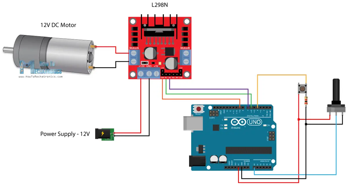
L298N Motor Driver
The L298N is a dual H-bridge driver allowing control of speed and direction of two DC motors.
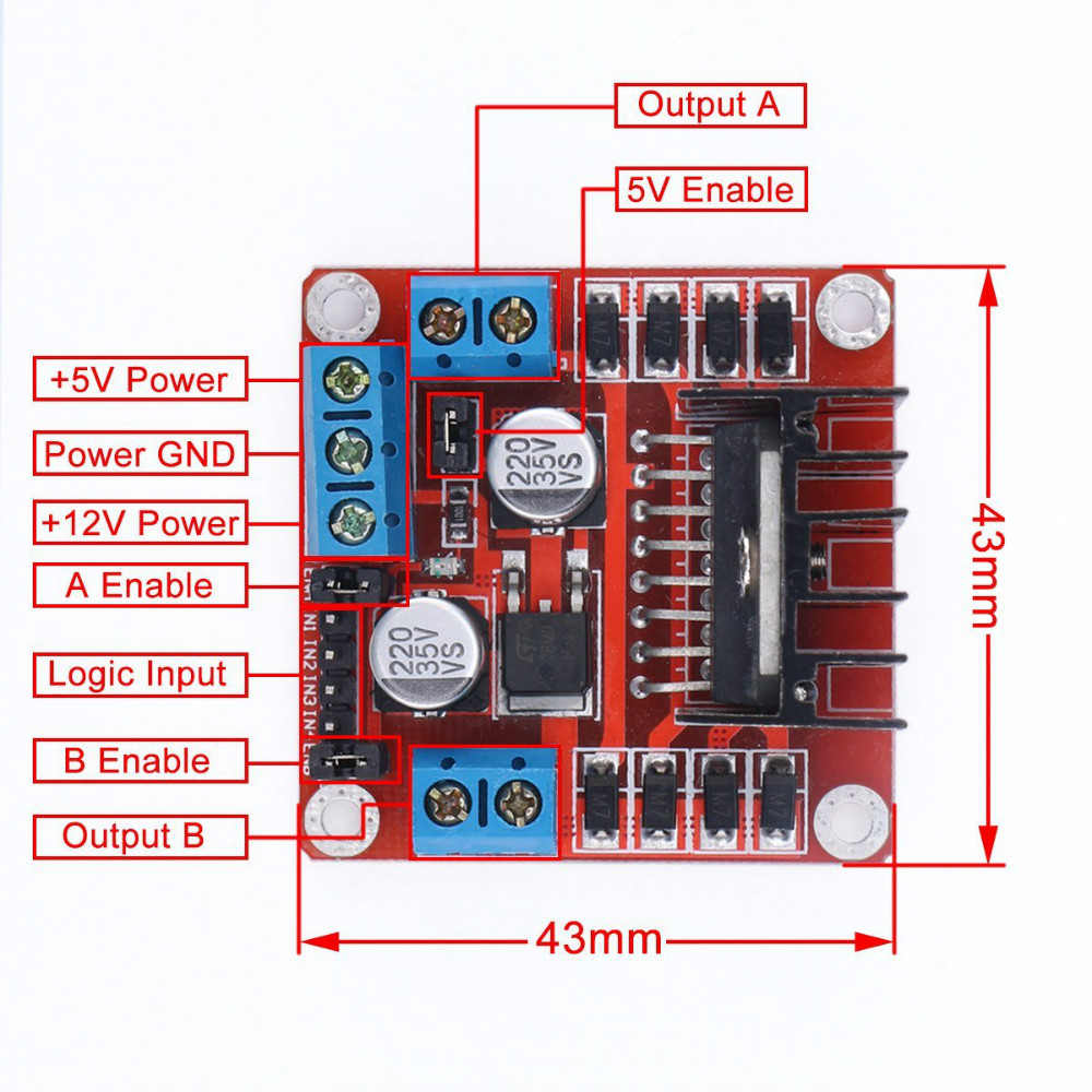
Key Pins:
- ENA/ENB: Enables motor A/B
- IN1/IN2: Controls direction of Motor A
- IN3/IN4: Controls direction of Motor B
- Vcc: Power input (5-35V)
- GND: Ground
Circuit Diagrams
Arduino Code
#define enA 9
#define in1 6
#define in2 7
#define button 4

int rotDirection = 0;
bool pressed = false;

void setup() {
  pinMode(enA, OUTPUT);
  pinMode(in1, OUTPUT);
  pinMode(in2, OUTPUT);
  pinMode(button, INPUT);

  digitalWrite(in1, LOW);
  digitalWrite(in2, HIGH);
}

void loop() {
  int potValue = analogRead(A0);
  int pwmOutput = map(potValue, 0, 1023, 0, 255);
  analogWrite(enA, pwmOutput);

  if (digitalRead(button)) {
    pressed = !pressed;
    while (digitalRead(button));
    delay(20);
  }

  if (pressed && rotDirection == 0) {
    digitalWrite(in1, HIGH);
    digitalWrite(in2, LOW);
    rotDirection = 1;
    delay(20);
  }

  if (!pressed && rotDirection == 1) {
    digitalWrite(in1, LOW);
    digitalWrite(in2, HIGH);
    rotDirection = 0;
    delay(20);
  }
}
Applications
- Robotic vehicle control
- Paper mill motors
- Escalators and elevators
- Industrial automation
TASK 3: 3D Printing
What is 3D Printing?
3D printing is a process of creating a physical object from a digital model by depositing layers of material.

Important Files
- STL File: 3D model format
- GCODE File: Instructions for 3D printer
Slicing
The process of converting STL into GCODE using slicer software like Ultimaker Cura or Creality Slicer.

Website for STL Files
Key Terms
- Bed Temperature: 50–60°C (for PLA)
- Nozzle Temperature: 205–210°C (for PLA)
- Infill Density: 20% for visual models

Working in Marvel Lab
TASK 4: 555 Astable Multivibrator
Overview
A 555 Astable Multivibrator generates continuous pulses. It acts as a basic timer oscillator.

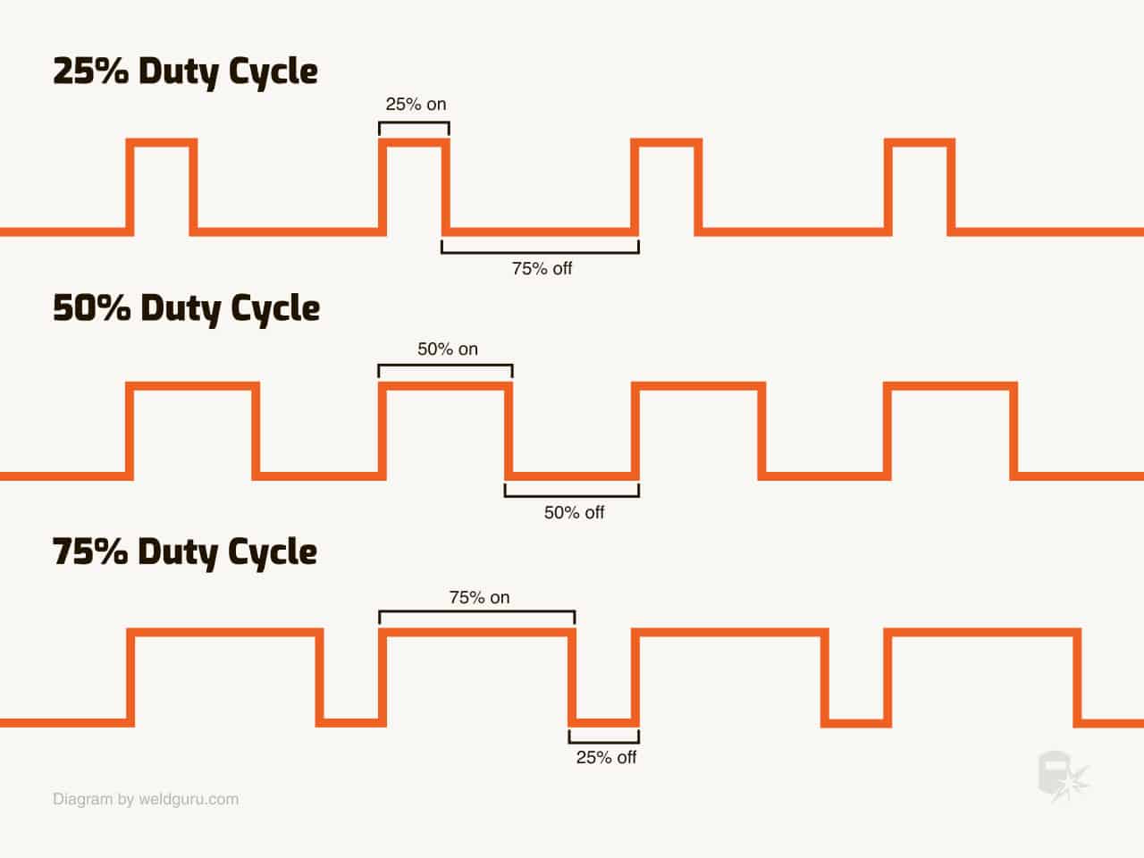
Duty Cycle
Duty Cycle = (R1 + R2) / (R1 + 2R2) * 100%
- Desired: 60% ON, 40% OFF
Formulas
T1 = 0.693 × (R1 + R2) × C
T2 = 0.693 × R2 × C
Components
- Breadboard
- Jumper wires
- Capacitor (0.01 µF)
- Resistors (10k and 22k)
Applications
- Traffic light systems
- Timers in electronics
- Frequency generators
Marvel Lab Experiment
TASK 5: Soldering Prerequisites
Soldering is a method to join two metal surfaces using a melted alloy called solder.
Tools & Materials
Solder
- Alloy of lead and tin

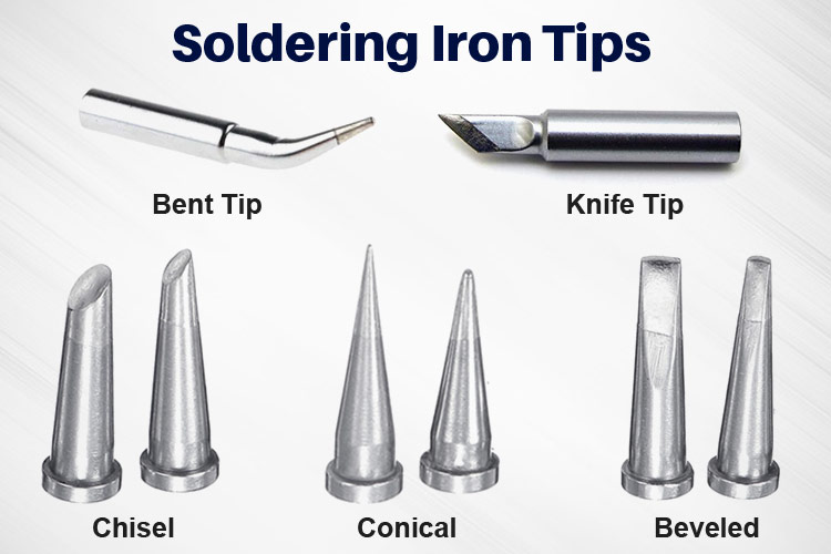
Soldering Iron
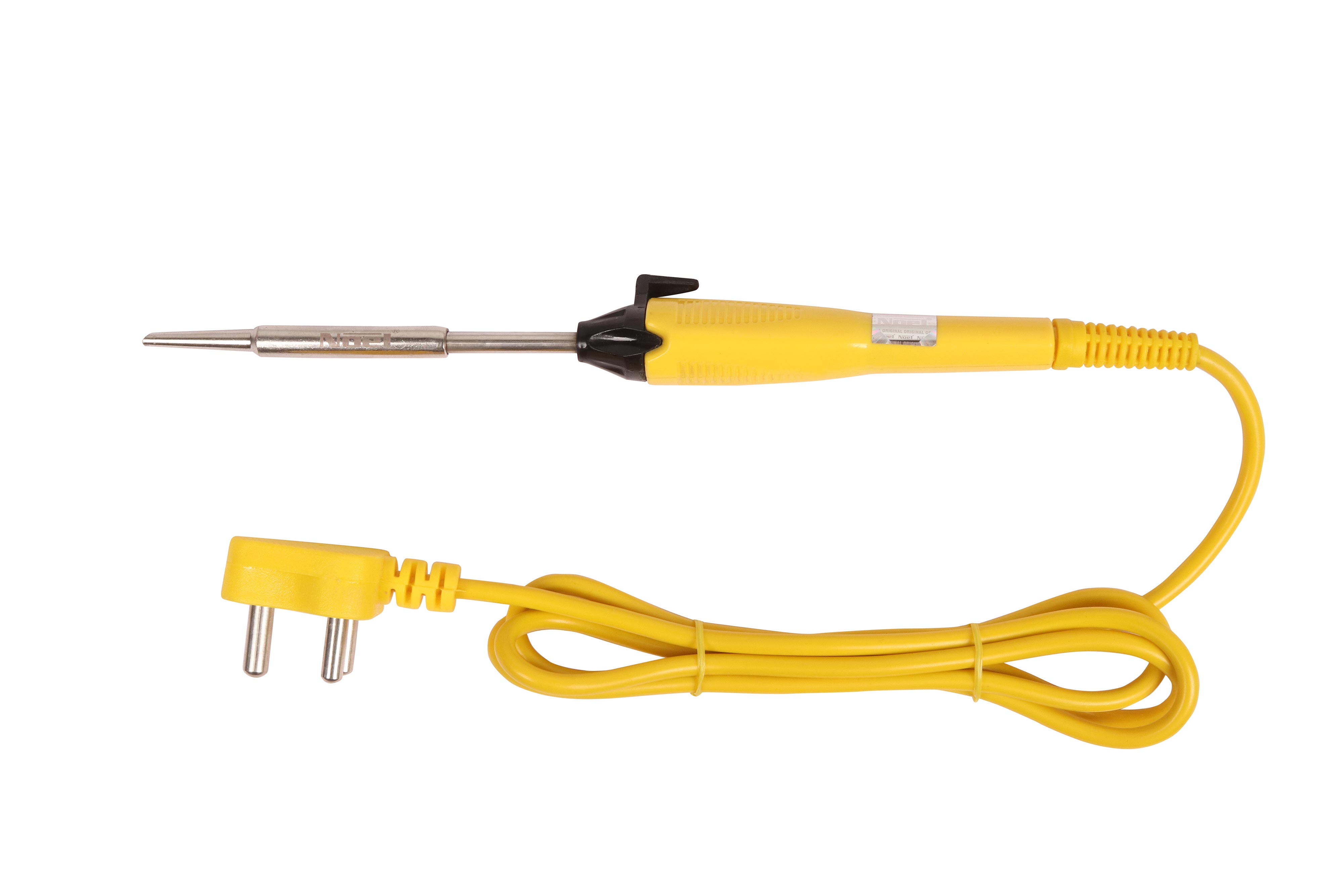
⚠️ Caution: Do not touch tip when hot!
Desoldering Wick

Soldering Flux

Soldering Stand

Chisel Tip
Marvel Lab Soldering Activity
- Soldered components: LED, Resistor, PCB
- Power connected externally to light the LED