BLOG · 11/2/2024

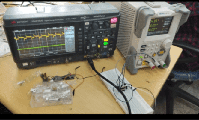
TASK 13:\n Design a 555 astable multivibrator with a duty cycle 60%, rig up the circuit on a breadboard, and by using the probes observe the output of your circuit on the DSO.\nBasic Astable 555 Oscillator: The 555 IC can function as an astable oscillator to generate continuous square wave pulses. It operates by continuously re-triggering itself, allowing it to function as a free-running oscillator.\n\ncircuit configuration: Connect pins 2 (trigger) and 6 (threshold) together to enable re-triggering for astable operation. The timing resistor from the monostable circuit is split into two resistors, R1 and R2.\n\nWaveform Generation: During each cycle, the capacitor charges through both R1 and R2 but discharges only through R2. Output waveform voltage level is approximately Vcc−1.5V.\n\nCharge and Discharge Times: Charge time (t1) and discharge time (t2) determine the frequency of oscillations. T=t1+t2, where T is the total periodic time.\n\nOutput Frequency Equation: f=1/T=1/(t1+t2).\n\nDuty Cycle Adjustment: The duty cycle can be adjusted by changing the ratio of resistors R2 to R1. The duty cycle is the ratio of the \ON" time to the "OFF" time.\n\n"